Home ▸ STM32 Tutorials ▸
Published: August 7, 2021
Last Updated: March 23, 2026
Last Updated: March 23, 2026
How to Set Up a UDP Server on STM32 Using lwIP Raw API
This is Part 2 of the STM32 Ethernet series. In Part 1, we configured the hardware and ran a ping test. Now we go one step further – we set up a UDP Server on STM32 using the lwIP Raw API.
UDP is the simplest networking protocol. It has no handshake, no acknowledgment, and no connection state to manage. This makes it fast and lightweight – a perfect starting point before we move to TCP.
In this tutorial, we will write the UDP server code step by step, explain what each part does, and test it from a PC.
What Is a UDP Server and Why Use It on STM32?
UDP stands for User Datagram Protocol. It is one of the core protocols in the TCP/IP networking stack. Unlike TCP, UDP does not establish a connection before sending data. It simply sends a packet to a target IP and port and moves on. There is no handshake, no acknowledgment, and no guarantee of delivery.
This might sound like a limitation. But in many embedded applications, it is actually a feature. When you need speed and low overhead, UDP is the right choice.
How UDP Communication Works
The communication model is straightforward. The server binds to a specific IP address and port number. It then waits for incoming packets. When a client sends a UDP packet to that IP and port, the server receives it. The server can optionally send a reply back to the client.
That’s the entire flow:
- Client sends a packet to the server’s IP and port
- Server receives the packet
- Server reads the data and sends a reply (optional)
- Client receives the reply
There is no “connection” being maintained. Every packet is independent. The server does not know whether the client is still online, and it does not care. This is what makes UDP so lightweight.
On STM32, we use the lwIP Raw API to implement this. The Raw API is callback-based. We register a function, and lwIP calls it automatically every time a UDP packet arrives. We do not have to poll or block.
UDP vs TCP (Quick Comparison)
Choosing between UDP and TCP depends on what your application needs. Here is a quick side-by-side look:
| Feature | UDP | TCP |
|---|---|---|
| Connection setup | None | 3-way handshake required |
| Delivery guarantee | No | Yes |
| Data ordering | No | Yes |
| Speed | Faster | Slower |
| Overhead | Low | Higher |
| Use case | Sensor data, commands, streaming | File transfer, HTTP, reliable data |
For our STM32 project, we start with UDP because it is simpler to implement and easier to debug. Once you understand the flow here, moving to TCP in a later tutorial becomes much easier.
Why Use UDP on STM32 Specifically?
STM32 microcontrollers have limited RAM and processing power. TCP has more overhead as it needs to track connection state, handle retransmits, and manage buffers for both directions. For a small MCU, all of that adds up.
UDP, on the other hand, is a much better fit when:
- You are sending periodic sensor readings to a PC or server
- You need fast, low-latency command transmission
- Your application can tolerate occasional packet loss
- You want to broadcast data to multiple devices on the network
I started this series with UDP for exactly these reasons. It is the simplest ethernet protocol to run on STM32.
STM32 CubeMX Ethernet Configuration
After enabling the Ethernet, you must cross check the pins configured by the CubeMX with the schematic of the board. Most of the times, the pins are configured incorrectly and it becomes one of the most popular error for the ethernet to not work.
STM32 Ethernet Configuration
There are many types of configurations available with different MCUs. Some MCUs let you configure the memory in the CubeMX, while others don’t. Some of the Boards have the MII Type Hardware, while other have RMII Type.
Below is the picture showing different configuration available in different ST Boards.
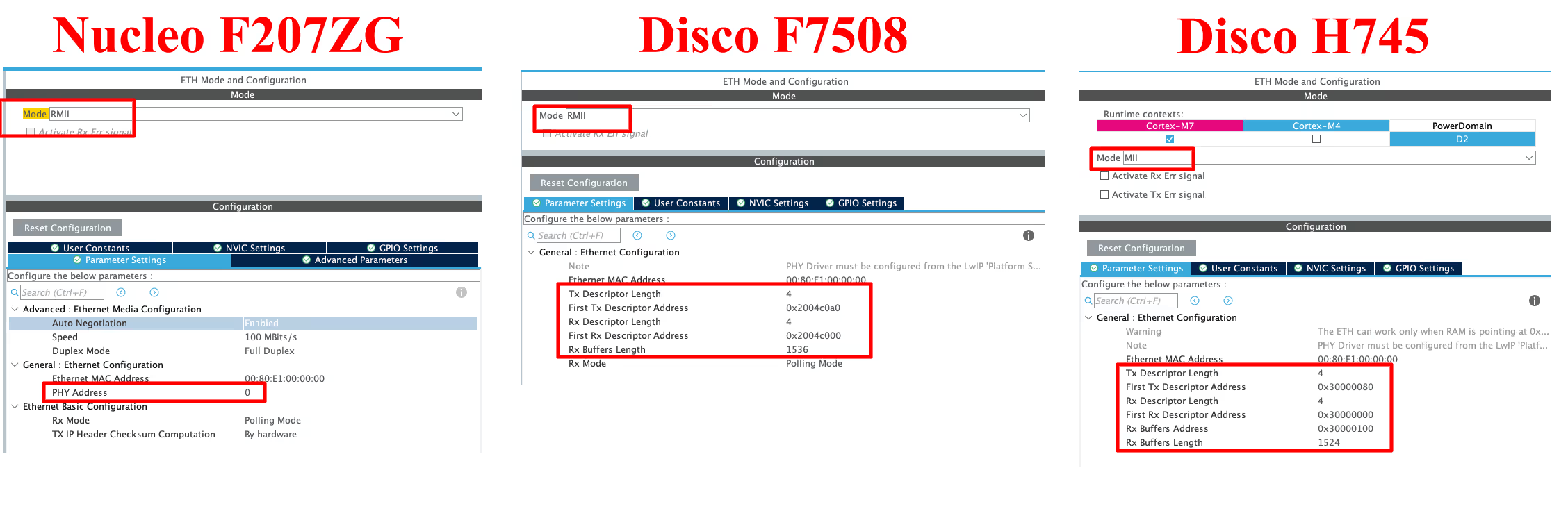
- The First board (Nucleo F207ZG) and second board (Disco F7508) uses the RMII pinout, while the third board (Disco H745) uses the MII pinout.
- On the first board we have the option to choose the PHY Address. This should be set to 0, if you are using the on board LAN Port, and it should be 1 in case of the external module.
- The 2nd and 3rd boards allow us to configure the memory addresses while the first one does not. If your board does not allow the memory configuration, you can simply skip those steps.
- The H745 discovery board is letting us configure the addresses for Tx and Rx DMA descriptors, and for the Rx Buffer as well. But the F7508 Discovery board does not let us configure the address for the Rx Buffer.
- Assuming that each DMA Descriptor takes 32 bits (MAXIMUM Possible), the RX Descriptor and Tx Descriptor have a maximum size of 128 Bytes (32×4) each.
- The Memory between them is spaced keeping this 128 bytes in mind.
- The Rx Buffer length is set to 1524 Bytes (1536 Bytes in H745 Discovery), but the number of RX buffers to be used can be defined later in the LWIP configuration. By default the cubeMX sets the number to 12 buffers. This would make the total length of Rx Buffer around 18KB.
- The memories are allocated in the SRAM region, whose properties can be modified later in the MPU.
LWIP Setup in STM32CubeMX (Static IP, Heap, PHY settings)
The LightWeight IP can be enabled in the middleware section. If the MCU does not let you enable it, make sure the cache (DCache and ICache) are enabled.
The most of the Configuration in the LWIP remains same. Except, some MCUs let us choose the address for the Heap.
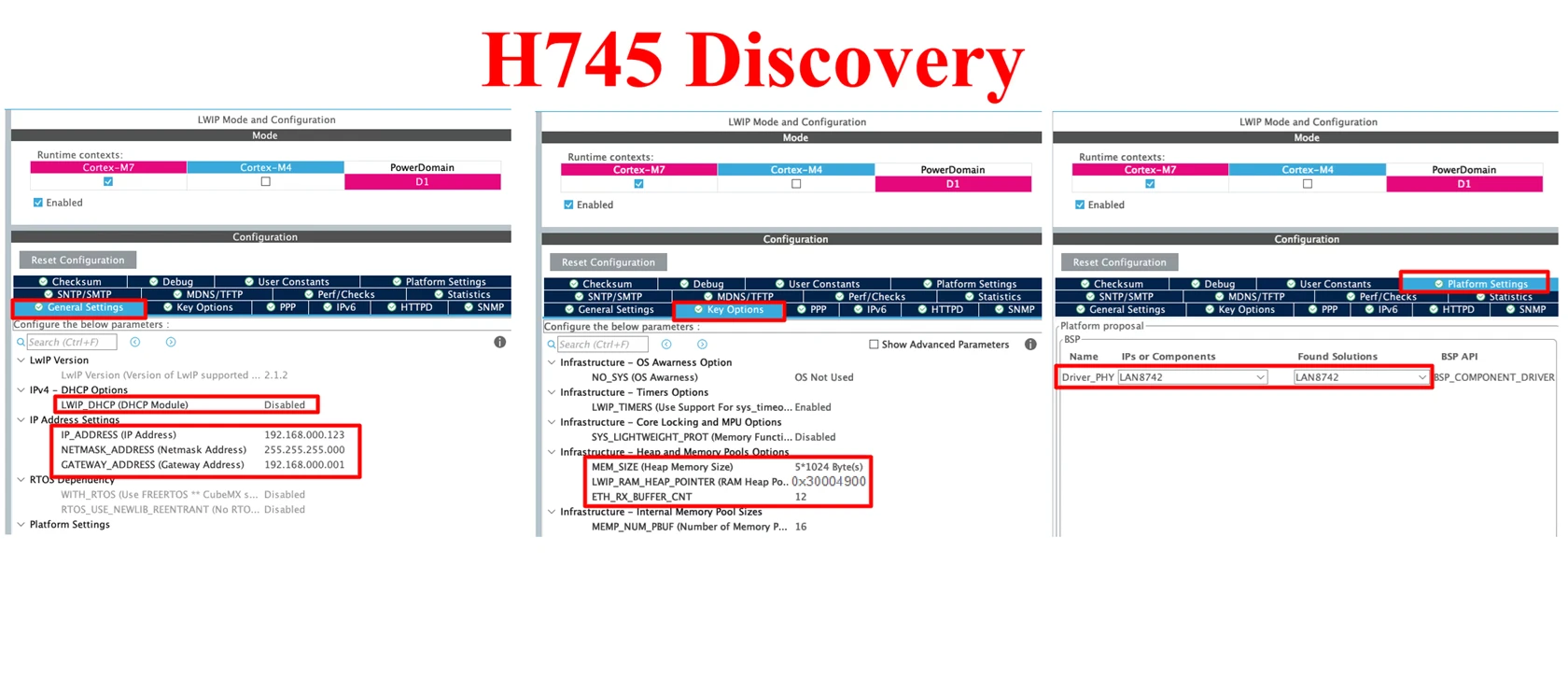
- Here we are going to disable the DHCP, and configure a static IP for our ethernet module. I have set the IP 192.168.0.123 for the board.
- In the Key Option tab, I am using 5KB memory for the Heap. The location for this heap is defined as 0x30004900.
- In the Platform Settings tab, set the PHY as LAN8742.
STM32 MPU Setup for Ethernet (Cache Coherency Fix for Cortex M7)
We have the DMA Descriptors in the SRAM Region. This is why we need to configure the MPU.
If your MCU didn’t let you choose the memory region, then probably you don’t need to do it. But for the cortex M7 devices, this is a must, or else you will get hardfault.
Remember that during the configuration, we set up everything in the SRAM (0x30000000). The complete memory structure is shown in the image below.
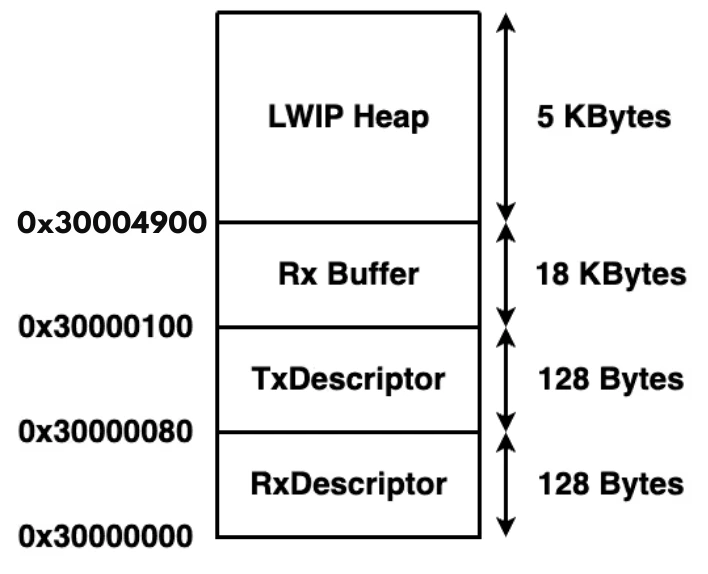
Below is the image showing the MPU configuration for the above Region.
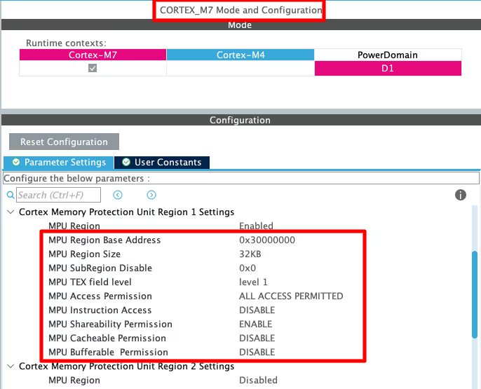
- Here I have selected the 32 KB region so that it will cover our total RAM region, which is around 24KB.
- The rest of the configuration is to set the region as non-cacheable region.
- This would prevent the cache coherency issue between the CPU and the DMA.
- This is explained in the cortex M7 playlist, so do check that out.
Once the project is generated, open the LWIP -> Target -> ethernetif.c file. Here you will some memory locations that needs to be defined in the flash script file.
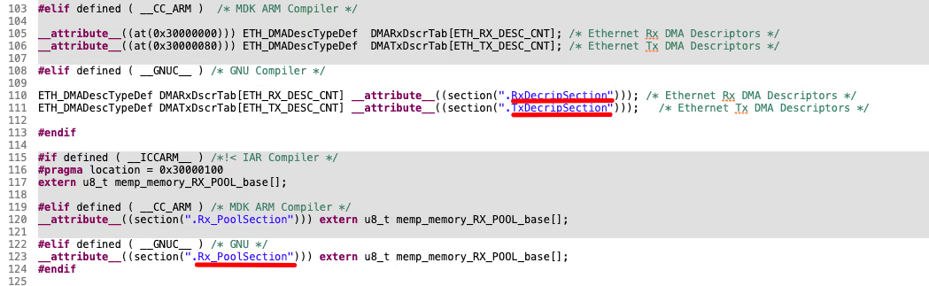
We need to define these memory locations in the flash script file, as per the configuration done in the cubeMX.
Flash script Modification
Below is the code is for the H745 Discovery board according to the configuration done in the CubeMX.
    .lwip_sec (NOLOAD) : {
    . = ABSOLUTE(0x30000000);
    *(.RxDescripSection)

    . = ABSOLUTE(0x30000080);
    *(.TxDescripSection)

    . = ABSOLUTE(0x30000100);
    *(.Rx_PoolSection)
} >RAM_D2Below is the code is for the F7508 Discovery board according to the configuration done in the cubeMX.
    .lwip_sec (NOLOAD) :
  {
    . = ABSOLUTE(0x2004C000);
    *(.RxDecripSection)

    . = ABSOLUTE(0x2004C0A0);
    *(.TxDecripSection)
} >RAMOther Configuration Required for Ethernet
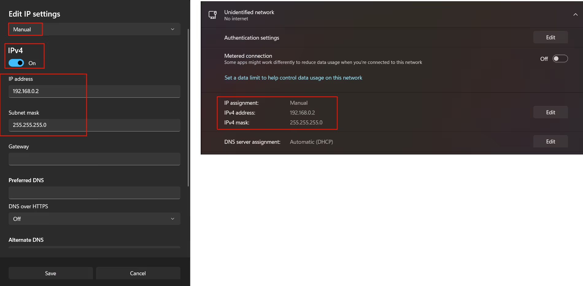
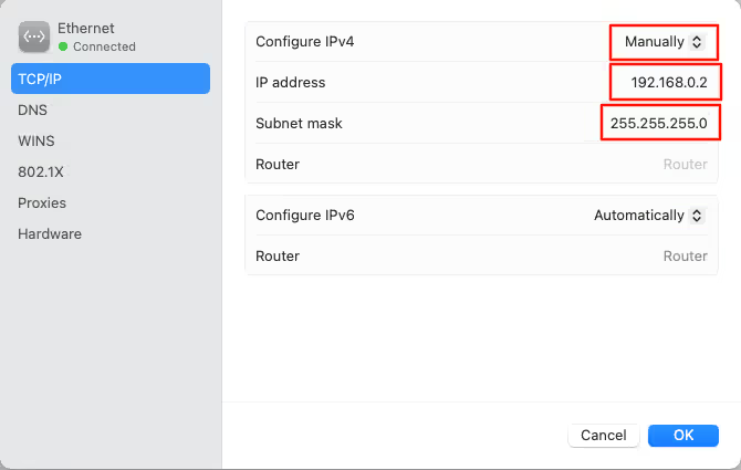
If you are connecting the STM32 board to the Router, there is nothing you need to do at the computer end. But if you are connecting the ethernet cable directly to the computer, you need to configure your computer’s ethernet as per the images shown below.
Below is the configuration for a Windows computer.
Below is the configuration for Mac.
Writing the STM32 UDP Server Code
The UDP server code lives in a separate file udp_server.c with its header udp_server.h. This keeps the code clean and separate from the auto-generated CubeMX files.
The implementation has three parts: the server init function, the receive callback, and a small update to main(). Let’s go through each one in detail.
Step 1: Initialize the UDP Server
The first thing we need is a UDP Protocol Control Block (PCB). This is a structure defined by lwIP that holds everything about a UDP endpoint -> the local IP address, the local port, and the callback function to invoke when data arrives.
We declare it locally inside the init function:
struct udp_pcb *upcb;
err_t err;err_t is lwIP’s error type. We will use it to check whether each step succeeded before moving on.
Creating the PCB
We call udp_new() to allocate and zero-initialise a new UDP PCB:
upcb = udp_new();This does not bind to any address yet. It just gives us an empty control block to work with. If udp_new() returns NULL, it means lwIP ran out of memory.
Binding to a local IP and port
Next, we bind the PCB to our STM32’s static IP address and the port we want to listen on. The IP address must first be converted into lwIP’s internal ip_addr_t format using the IP_ADDR4() macro:
ip_addr_t myIPADDR;
IP_ADDR4(&myIPADDR, 192, 168, 0, 123);
err = udp_bind(upcb, &myIPADDR, 7);IP_ADDR4() takes four separate octets and packs them into the structure. The IP here (192.168.0.123) must match the static IP we configured in CubeMX for the board. Port 7 is the classic “echo” port and is a good choice for testing.
udp_bind() registers this PCB as the owner of packets arriving at that IP and port. Once this call succeeds, lwIP knows to route any UDP packet destined for 192.168.0.123:7 to this PCB.
Registering the receive callback
After a successful bind, we register the callback function that lwIP will call automatically every time a UDP packet arrives:
if(err == ERR_OK)
{
udp_recv(upcb, udp_receive_callback, NULL);
}
else
{
udp_remove(upcb);
}udp_recv() takes three arguments: the PCB, the callback function, and an optional user-argument pointer (we pass NULL here since we don’t need it). From this point on, the server is live. Any incoming UDP packet on port 7 will trigger udp_receive_callback().
If the bind failed for any reason, we call udp_remove() to free the PCB and avoid a memory leak.
Here is the complete udpServer_init() function:
void udpServer_init(void)
{
struct udp_pcb *upcb;
err_t err;
/* 1. Create a new UDP control block */
upcb = udp_new();
/* 2. Bind the upcb to the STM32 static IP and port 7 */
ip_addr_t myIPADDR;
IP_ADDR4(&myIPADDR, 192, 168, 0, 111);
err = udp_bind(upcb, &myIPADDR, 7);
/* 3. Register the receive callback if bind succeeded */
if(err == ERR_OK)
{
    udp_recv(upcb, udp_receive_callback, NULL);
}
else
{
    udp_remove(upcb);
}
}Step 2: Handle Incoming Data with the Receive Callback
When a UDP packet arrives on port 7, lwIP calls udp_receive_callback() and passes everything we need directly as function arguments. The function is defined below:
void udp_receive_callback(void *arg, struct udp_pcb *upcb,
struct pbuf *p, const ip_addr_t *addr, u16_t port)Here is what each parameter carries:
@arg: the user pointer we passed toudp_recv(). We passedNULL, so we ignore this.@upcb: the same PCB from the init function. We reuse it to send the reply.@p: a packet buffer (pbuf) containing the received data.p->payloadpoints directly to the raw data bytes.@addr: the IP address of the client that sent the packet.@port: the port number the client sent from. We need this to send the reply back.
Reading the incoming data
The received data is directly accessible through p->payload. We cast it to a char* and use it inside sprintf() to build the reply string:
char buf[100];
int len = sprintf(buf, "Hello %s From UDP SERVER\n", (char *)p->payload);This takes whatever text the client sent modifies it and sends it back. For example, if the client sent "STM32", buf will contain "Hello STM32 From UDP SERVER\n".
Allocating and filling the transmit buffer
lwIP does not let us send raw arrays directly. We need to wrap the reply data inside a pbuf first. We allocate one using pbuf_alloc():
struct pbuf *txBuf;
txBuf = pbuf_alloc(PBUF_TRANSPORT, len, PBUF_RAM);PBUF_TRANSPORT tells lwIP to leave space for transport-layer headers above our data. PBUF_RAM allocates the buffer from the heap. The second argument len is the size of our payload.
Then we copy our reply string into the buffer:
pbuf_take(txBuf, buf, len);pbuf_take() copies len bytes from buf into the payload area of txBuf. After this call, the packet buffer is ready to send.
Sending the reply
To send data back to the client, we first need to tell the PCB who the client is. We do this with udp_connect():
udp_connect(upcb, addr, port);This sets the remote IP and port on the PCB temporarily. Now upcb knows the destination. We then send the buffer:
udp_send(upcb, txBuf);udp_send() takes the PCB (which now has the remote address) and the packet buffer, wraps it in a UDP header, and hands it off to the Ethernet layer. The packet goes out on the wire.
Disconnecting and freeing memory
After sending, we must disconnect the PCB so the server can accept packets from other clients:
udp_disconnect(upcb);This clears the remote IP and port from the PCB. Without this call, the PCB would only ever respond to the first client that connected — all other packets would be ignored.
Finally, we free both packet buffers. This is critical:
pbuf_free(txBuf);
pbuf_free(p);lwIP uses reference-counted memory for pbufs. Every pbuf_alloc() must have a matching pbuf_free(). If we forget to free p (the incoming packet), lwIP will run out of packet buffers after a while and the server will stop responding.
Here is the complete callback function:
void udp_receive_callback(void *arg, struct udp_pcb *upcb,
                           struct pbuf *p, const ip_addr_t *addr, u16_t port)
{
struct pbuf *txBuf;
/* Build the reply string using the received payload */
char buf[100];
int len = sprintf(buf, "Hello %s From UDP SERVER\n", (char *)p->payload);
/* Allocate a pbuf for the reply */
txBuf = pbuf_alloc(PBUF_TRANSPORT, len, PBUF_RAM);
/* Copy the reply data into the pbuf */
pbuf_take(txBuf, buf, len);
/* Set the client as the destination and send */
udp_connect(upcb, addr, port);
udp_send(upcb, txBuf);
/* Disconnect so the server is ready for the next client */
udp_disconnect(upcb);
/* Free both buffers — never skip this */
pbuf_free(txBuf);
pbuf_free(p);
}Step 3: The Main Function
The main() function needs only two small additions compared to Part 1. We call udpServer_init() once during startup, and then we drive the lwIP stack inside the infinite loop.
Here is the complete main():
int main(void)
{
    MPU_Config();

    /* Enable I-Cache */
    SCB_EnableICache();

    /* Enable D-Cache */
    SCB_EnableDCache();

    HAL_Init();
    SystemClock_Config();
    MX_GPIO_Init();
    MX_LWIP_Init();

    /* USER CODE BEGIN 2 */
    udpServer_init();
    /* USER CODE END 2 */

    while (1)
    {
        MX_LWIP_Process();
    }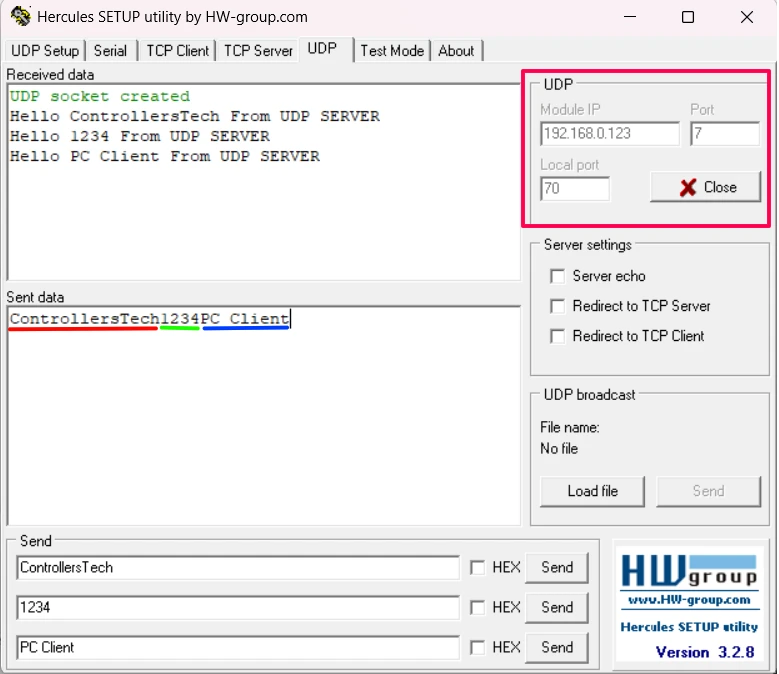
}Testing the STM32 UDP Server
The image below shows the data sent by the client (Hercules) and the reply received from the STM32 UDP server. You can see the server echoes back the message in the expected format, confirming the connection is working correctly.
Video Tutorial
STM32 UDP Server Video Tutorial
This STM32 UDP Server tutorial shows you the complete code and testing process in action. I walk you through the udpServer_init function, the receive callback, and the main loop step by step. Watch the video and follow the written guide together to easily set up a UDP Server and test it from your PC.
Watch the UDP Server TutorialConclusion
We now have a working UDP server running on STM32 with lwIP. The setup involved three things: initializing the UDP PCB, registering a receive callback, and calling MX_LWIP_Process() in the main loop.
UDP is stateless, so the server can serve multiple clients as long as we call udp_disconnect() after each reply. The same loop structure will carry forward into the next tutorials.
In Part 3, we will flip this around and configure the STM32 as a UDP Client, sending data to a PC server instead of receiving it.
Check out more STM32 Ethernet Tutorials
STM32 Ethernet Tutorial (PART 4): TCP Server with lwIP Raw API
STM32 Ethernet Tutorial (PART 5): TCP Client with lwIP Raw API
STM32 Ethernet PART 6 – How to Configure Simple HTTP Webserver
STM32 Ethernet PART 6.1 – Configure HTTP Webserver using SSI

STM32 Ethernet PART 6.2 – Configure HTTP Webserver using CGI
STM32 Ethernet PART 7 – UDP Server using LWIP NETCONN (RTOS)


used the example you showed in the video, works fine, but when I ping to the stm32, only 50% or 25% ping succeeds, otherwise telling I get 50% loss of ping.
I am working with a team and we are all connected over a switch and if some one sends every 0.01 sec a packet of 32 Byte, then my board will be busy receiving this packts and then ignore it, but my Ping will be lost and i cant communicate with my board, any solutions??
if no one sending packets over the switch, then i can ping the board
hi, i want to send 1600 byte array (array[1600]) with udp from mcu to pc(server).can any one help me????
Thanks mate, greatly appreciate these ethernet guides!
The tutorials are really great. Keep doing this good job and sharing knowledge.