
Published: November 13, 2025
Last Updated: February 6, 2026
Last Updated: February 6, 2026
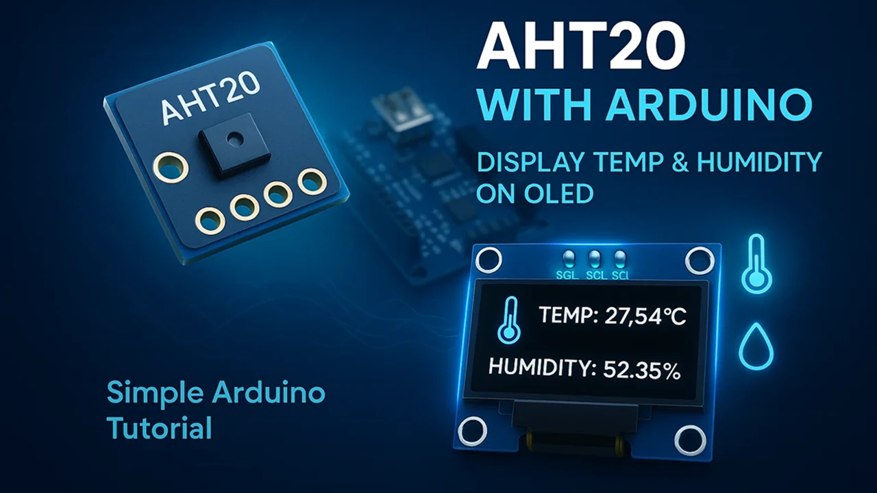
How to Interface AHT20 Temperature and Humidity Sensor with Arduino
Measuring temperature and humidity is a common requirement in most weather monitoring and IoT projects. The AHT20 sensor is a reliable and accurate digital sensor that communicates with Arduino using the I²C protocol. It’s compact, easy to connect, and provides fast and stable readings.
In this tutorial, we’ll learn how to interface the AHT20 sensor with Arduino and display its readings on both the Serial Monitor and a 0.96″ OLED SSD1306 display. You’ll see how simple it is to read temperature and humidity data and show it on a small OLED screen.
We’ll cover the pinout, wiring, and Arduino code in detail so even beginners can follow easily. For displaying data on the OLED, we’ll also link to our detailed guide — Arduino SSD1306 OLED Display Tutorial.
Introduction to AHT20 Sensor
The AHT20 is a modern digital sensor designed to measure both temperature and humidity with high accuracy and stability. It is widely used in various electronic and IoT projects because it provides reliable readings, communicates easily through the I²C interface, and requires very little setup.
Let’s take a closer look at what this sensor is, its key specifications, and where you can use it.
What is AHT20 Sensor?
The AHT20 sensor is a digital temperature and humidity sensor developed by ASAIR. It works on the I²C communication protocol, making it compatible with most microcontrollers like Arduino, ESP32, STM32, and others.
This sensor contains a calibrated capacitive humidity sensor and a thermistor integrated into a compact module. The onboard 14-bit ADC (Analog-to-Digital Converter) ensures precise and stable measurements with minimal drift over time.
AHT20 is the successor of the popular AHT10 sensor, offering better accuracy, improved response time, and more consistent readings across different temperature ranges. It operates on 3.3V to 5V, which means it can be directly powered by an Arduino board without level shifting.
Features and Specifications of AHT20
Here are the main features and technical specifications of the AHT20 sensor:
- Operating Voltage: 2.0V to 5.5V (compatible with 3.3V and 5V logic)
- Interface: I²C (default address 0x38)
- Humidity Range: 0% to 100% RH
- Temperature Range: -40°C to +85°C
- Humidity Accuracy: ±2% RH (typical)
- Temperature Accuracy: ±0.3°C (typical)
- Response Time: Less than 10 seconds
- Compact Size: Easy to integrate into small projects
- Fully Calibrated: No external components required
- Low Power Consumption: Suitable for battery-powered applications
These specifications make the AHT20 a strong choice for projects that require precise and reliable environmental monitoring.
Applications of AHT20 Sensor
The AHT20 sensor is used in a wide range of practical applications. Some of the most common uses include:
- Weather Monitoring Systems – To measure and track local temperature and humidity.
- IoT Environmental Projects – Ideal for smart home or greenhouse monitoring.
- HVAC Systems – For controlling and maintaining indoor air quality.
- Data Logging Devices – To record environmental changes over time.
- Consumer Electronics – Used in air purifiers, dehumidifiers, and thermostats.
Because of its high accuracy and small form factor, the AHT20 is perfect for Arduino-based weather stations, indoor air monitoring systems, and other projects that need environmental data in real time.
AHT20 Pinout and Connection with Arduino
Let’s start by taking a look at the pinout of the AHT20 sensor to understand its available connections and functions. Once we are familiar with the pins, we’ll move on to the wiring part, where we’ll see how to properly connect the AHT20 to an Arduino board for data communication.
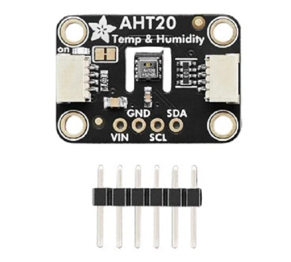
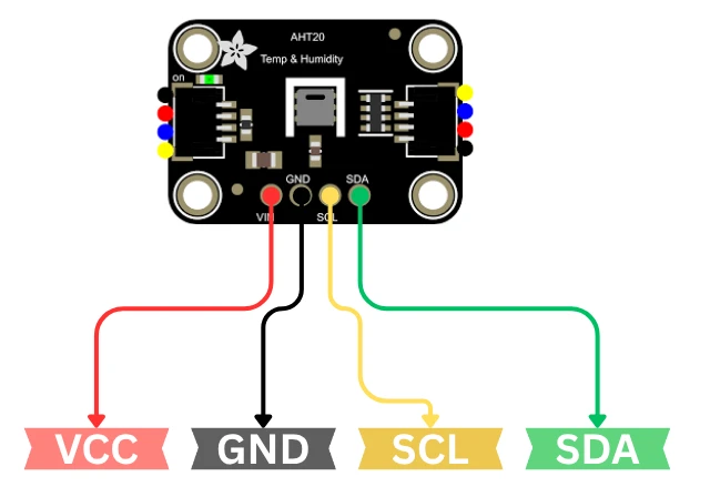
AHT20 Pin Configuration
The AHT20 sensor comes with a simple 4-pin interface, which makes it very easy to connect with an Arduino. Since it communicates over the I2C protocol, only two pins are used for data transfer — SDA and SCL. The remaining two pins are for power supply.
Most AHT20 breakout boards expose a small set of pins. Here are the common pins and their meaning:
| Pin Name | Description |
|---|---|
| VCC / VIN | Power supply. Accepts 3.3V to 5V. |
| GND | Ground connection. |
| SDA | I²C data line. |
| SCL | I²C clock line. |
| SDO / ADDR (optional) | I²C address select on some modules (often not present). |
| INT / DRDY (rare) | Interrupt / Data Ready pin on some variants. |
Note: The AHT20’s default I²C address is 0x38. Many breakout modules include onboard pull-up resistors on SDA and SCL. If yours does not, add 4.7kΩ pull-ups to VCC.
Circuit Diagram for AHT20 with Arduino
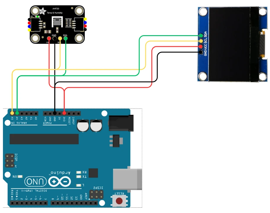
The circuit diagram for connecting the AHT20 sensor to Arduino is very straightforward. The image below shows how to connect the AHT20 sensor with Arduino UNO.

Below is a typical connection setup using the Arduino UNO:
| AHT20 Pin | Arduino UNO Pin |
|---|---|
| VCC | 3.3V or 5V |
| GND | GND |
| SDA | A4 |
| SCL | A5 |
If you use an Arduino Nano / Pro Mini (5V) the SDA and SCL pins are the same (A4, A5).
If you use an Arduino Leonardo / Micro or ESP32, use the board’s dedicated SDA and SCL pins. Check your board pinout.
If the module lacks pull-ups, connect two 4.7 kΩ resistors:
- one between SDA and VCC
- one between SCL and VCC
Displaying Temperature and Humidity on Serial Monitor
Once the AHT20 sensor is connected properly to the Arduino, we can begin reading temperature and humidity values. In this section, we’ll go step by step, from installing the required libraries to uploading the code and viewing the output on the Serial Monitor.
Required Arduino Libraries
To make the AHT20 sensor work smoothly with Arduino, we’ll use an existing library. This library handles all the communication with the sensor and simplifies the code.
You can install it directly from the Arduino Library Manager:
- Open Arduino IDE.
- Go to Sketch → Include Library → Manage Libraries.
- In the search bar, type AHT20.
- Install the library named “Adafruit AHTX0” by Adafruit.
This library supports both AHT10 and AHT20 sensors, so it works perfectly for our project.

Also, make sure you have the Adafruit BusIO library installed, as it’s a dependency for AHTX0.
Arduino Code to Read AHT20 Data
Once the libraries are installed, you can use the following Arduino sketch to read data from the AHT20 sensor and print it on the Serial Monitor.
#include <Wire.h>
#include <Adafruit_AHTX0.h>

Adafruit_AHTX0 aht;  // Create AHT20 object

void setup() {
  Serial.begin(9600);
  Serial.println("AHT20 Sensor Test");

  if (!aht.begin()) {
    Serial.println("Could not find AHT20 sensor. Check wiring!");
    while (1);
  }
  Serial.println("AHT20 sensor found successfully!");
}

void loop() {
  sensors_event_t humidity, temperature;
  aht.getEvent(&humidity, &temperature); // Get new readings

  Serial.print("Temperature: ");
  Serial.print(temperature.temperature);
  Serial.println(" °C");

  Serial.print("Humidity: ");
  Serial.print(humidity.relative_humidity);
  Serial.println(" %");

  Serial.println("-------------------------");
  delay(2000); // Wait 2 seconds between readings
}Explanation:
- The code starts by including the Wire and Adafruit_AHTX0 libraries.
- We create an
ahtobject to communicate with the sensor. - In the
setup(), we initialize the serial monitor and the sensor. If the sensor is not found, it displays an error. - In the
loop(), we usegetEvent()to read both temperature and humidity values, and then print them on the serial console.
The delay of 2 seconds gives enough time to read the output clearly.
Output on Serial Console
Once the code is uploaded successfully, open the Serial Monitor from the Arduino IDE (Tools → Serial Monitor) and set the baud rate to 9600.

You’ll notice the values update every 2 seconds. The readings may vary slightly depending on the room temperature and humidity.
This confirms your AHT20 sensor is working perfectly, and your Arduino can successfully read and display environmental data.
Display AHT20 Sensor Data on 0.96″ OLED (SSD1306)
After verifying that the AHT20 sensor works correctly on the Serial Monitor, the next step is to make the output more visual. In this section, we’ll display the temperature and humidity readings on a 0.96″ OLED display based on the SSD1306 driver.
This compact OLED is perfect for small projects because it uses minimal power and communicates through the same I²C interface as the AHT20. That means both the OLED and the sensor can share the same SDA and SCL lines on your Arduino.
If you want to get more information about how to interafce the 0.96″ Oled display with Arduino, check out this guide: Interface 0.96″ SSD1306 Oled with Arduino.
Connecting OLED Display with Arduino
The 0.96″ SSD1306 OLED has four pins: VCC, GND, SCL, and SDA. Since it also uses the I²C protocol, the wiring is very similar to the AHT20 sensor.
You can connect both devices on the same I²C bus as shown below:
Both modules will work together without interference because:
- The AHT20 uses I²C address 0x38
- The OLED typically uses I²C address 0x3C
This means you can easily read sensor data and print it on the OLED display.
Once the hardware connection is done, the next step is to prepare your Arduino IDE so that it can communicate with the SSD1306 OLED display. We’ll use two official libraries from Adafruit that make working with the OLED display very simple — the Adafruit SSD1306 library and the Adafruit GFX library.
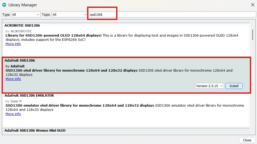
Installing Adafruit SSD1306 and GFX Libraries
To begin, open your Arduino IDE and follow these steps:
- Go to the Sketch menu → Include Library → Manage Libraries…
- In the Library Manager, type “SSD1306” in the search bar.
- Find Adafruit SSD1306 by Adafruit and click Install.
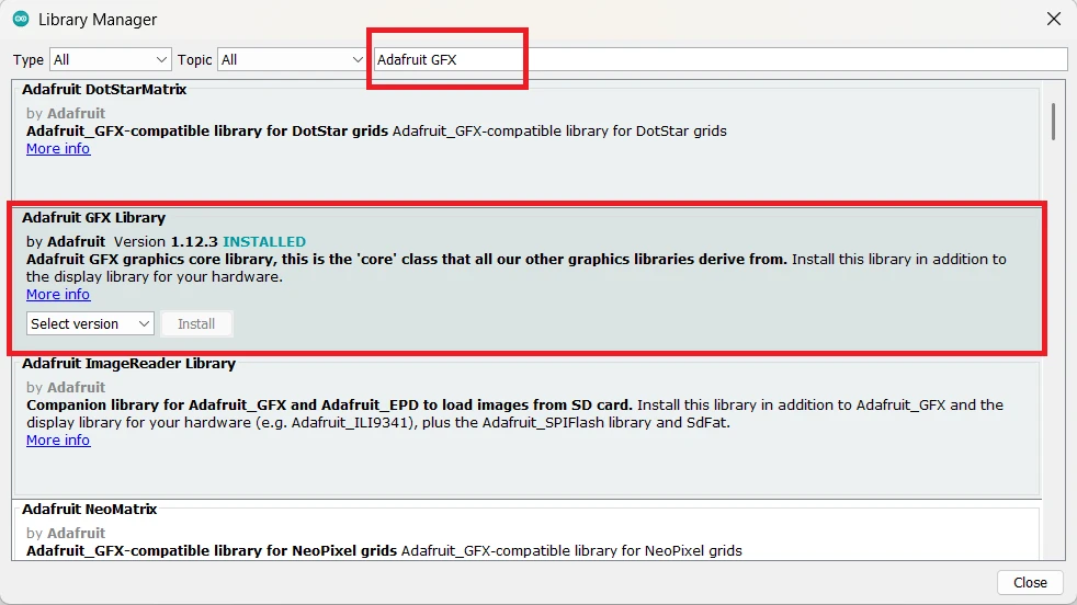
- Next, search for “Adafruit GFX” and install Adafruit GFX Library as well.
Arduino Code to Display AHT20 Data on OLED
Make sure you have installed the following libraries before running the code:
- Adafruit AHTX0 (for AHT20 sensor)
- Adafruit SSD1306 (for OLED display)
- Adafruit GFX (a graphics library required by SSD1306)
Now upload this code:
#include <Wire.h>
#include <Adafruit_GFX.h>
#include <Adafruit_SSD1306.h>
#include <Adafruit_AHTX0.h>

#define SCREEN_WIDTH 128
#define SCREEN_HEIGHT 64
Adafruit_SSD1306 display(SCREEN_WIDTH, SCREEN_HEIGHT, &Wire, -1);
Adafruit_AHTX0 aht;

void setup() {
  Serial.begin(9600);
  if (!aht.begin()) {
    Serial.println("Could not find AHT20 sensor. Check wiring!");
    while (1);
  }

  if (!display.begin(SSD1306_SWITCHCAPVCC, 0x3C)) {
    Serial.println("SSD1306 initialization failed!");
    while (1);
  }

  display.clearDisplay();
  display.setTextSize(1);
  display.setTextColor(SSD1306_WHITE);
  display.setCursor(0, 0);
  display.println("AHT20 Sensor Ready");
  display.display();
  delay(1000);
}

void loop() {
  sensors_event_t humidity, temperature;
  aht.getEvent(&humidity, &temperature);

  display.clearDisplay();
  display.setTextSize(1);
  display.setTextColor(SSD1306_WHITE);

  display.setCursor(0, 10);
  display.print("Temp: ");
  display.print(temperature.temperature);
  display.println(" C");

  display.setCursor(0, 30);
  display.print("Humidity: ");
  display.print(humidity.relative_humidity);
  display.println(" %");

  display.display();
  delay(2000);
}Code Explanation:
- The SSD1306 and AHTX0 libraries handle OLED and sensor communication through I²C.
- The display.begin() function initializes the OLED at address 0x3C.
- Inside the
loop(), we read temperature and humidity usinggetEvent()and print them on the OLED screen. - The display is refreshed every 2 seconds to show updated readings.
Tip: You can adjust the text size using the function display.setTextSize(). Right now its set to 1, if you want to increase the size, set it to 2 or 3.
Output on Oled Display
Once the code is uploaded successfully, you can see the Temperature and Humidity data on the Oled display. This is shown in the image below.
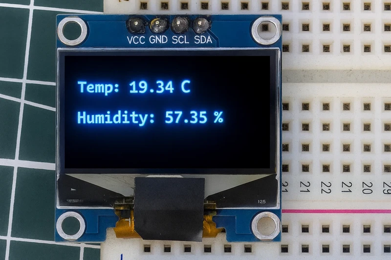
The values on the Oled display will update every 2 seconds. You can test the sensor by placing your finger on it, you should observe a sharp rise/fall in the Temperature and Humidity values.
Learn More About OLED Display with Arduino
If you’d like to explore more OLED functions — such as drawing graphics, displaying text in different sizes, or scrolling messages — check out our detailed tutorial on OLEDs:
Arduino SSD1306 OLED Display Tutorial
That guide explains how to use various display modes and text functions in the Adafruit SSD1306 library, which can help you create more advanced and attractive interfaces for your Arduino projects.
Troubleshooting Common Issues
Even though the AHT20 and OLED SSD1306 are easy to use, you might occasionally face some issues when testing the circuit. This section covers the most common problems and how to fix them quickly.
Sensor Not Detecting on I2C Bus
If your Arduino serial monitor shows an error like “Could not find AHT20 sensor”, it usually means the sensor isn’t detected on the I²C bus. Try the following checks:
- Check Wiring:
Make sure the SDA and SCL pins of the AHT20 are connected to the correct I²C pins on your Arduino.- On Arduino UNO/Nano: SDA = A4, SCL = A5
- On Arduino Mega: SDA = 20, SCL = 21
- On ESP32: SDA = 21, SCL = 22
- Run an I²C Scanner:
Upload a simple I²C scanner sketch to see if the AHT20 address (0x38) appears. If not, recheck the wiring or try another sensor. - Power Supply:
The sensor works between 2.0V and 5.5V, but make sure it is getting stable power. If you are using a breadboard, ensure the power lines are properly connected. - Pull-Up Resistors:
Some AHT20 modules don’t include onboard pull-ups on SDA and SCL. If yours doesn’t, add two 4.7kΩ resistors from each line (SDA, SCL) to VCC.
Wrong Temperature or Humidity Readings
If the sensor is detected but the readings seem off, here’s what you can check:
- Allow Warm-Up Time:
Give the sensor a few seconds after power-up before taking the first reading. It helps stabilize the internal elements. - Avoid Touching the Sensor:
Touching the sensing area or blowing directly on it can affect the readings. Handle it carefully to prevent heat and moisture interference. - Ventilation and Airflow:
Ensure the sensor is exposed to open air. Enclosed spaces or poor airflow can cause inaccurate humidity levels. - Add a Small Delay:
Avoid reading the sensor too frequently. A delay of 2 seconds between readings gives better accuracy and prevents data overlap. - Calibrate by Comparison:
Compare readings with another known good sensor to verify accuracy. Small variations (±2% RH, ±0.3°C) are normal.
OLED Not Displaying Data Properly
If the OLED screen remains blank or shows garbage data, follow these troubleshooting steps:
- Check I²C Address:
The SSD1306 OLED commonly uses 0x3C or 0x3D. If you’re not sure, run the I²C scanner and update the address in your code:display.begin(SSD1306_SWITCHCAPVCC, 0x3C); - Power Supply:
Ensure the OLED’s VCC is connected to 3.3V or 5V (depending on your module). Also check GND connection. - Library Installation:
Make sure both Adafruit SSD1306 and Adafruit GFX libraries are correctly installed. Without the GFX library, the display won’t work. - Initialization Sequence:
Confirm that the display is initialized before printing any data. You should calldisplay.begin()in the setup section. - Contrast and Refresh Issues:
If the screen is too dim, you can try adjusting brightness usingdisplay.ssd1306_command(SSD1306_SETCONTRAST);.
Also ensure you clear the display before writing new text usingdisplay.clearDisplay();. - Loose Wires:
Double-check the SDA and SCL connections. Poor contact or loose jumper wires are common reasons for a blank OLED screen.
Conclusion
In this tutorial, we learned how to interface the AHT20 temperature and humidity sensor with Arduino and display the readings on both the Serial Monitor and a 0.96″ OLED SSD1306 display. We covered everything from the sensor’s pinout and wiring connections to installing the required libraries and writing the Arduino code.
The AHT20 proved to be a reliable and accurate sensor that can easily communicate with Arduino using the I²C protocol. Combining it with the OLED display gives you a compact and attractive way to visualize environmental data in real time. This setup can serve as the base for many IoT or weather monitoring projects.
Browse More Arduino Sensors Tutorials
Arduino DS18B20 Temperature Sensor Tutorial: Single and Multiple Sensors with SSD1306 OLED

Interfacing SHT3X Temperature and Humidity Sensors with Arduino using I2C
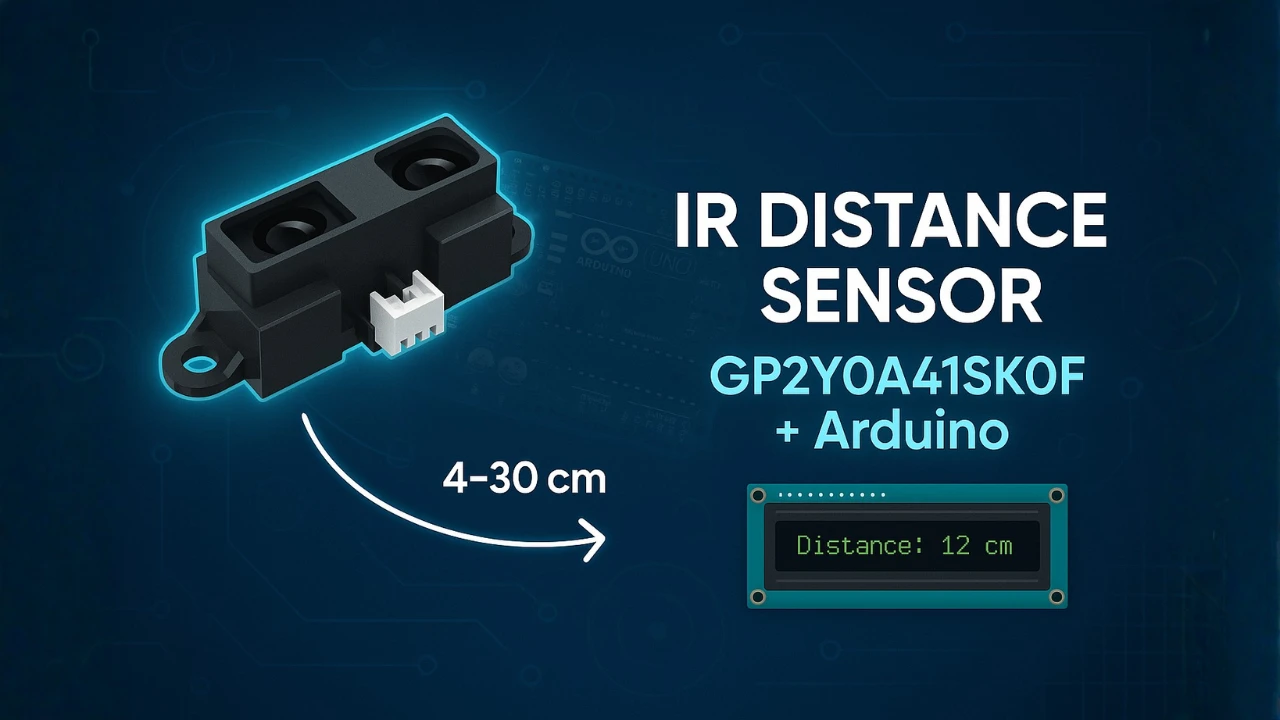
How to Interface GP2Y0A41SK0F Distance Sensor with Arduino (Serial Monitor + I2C LCD Display)
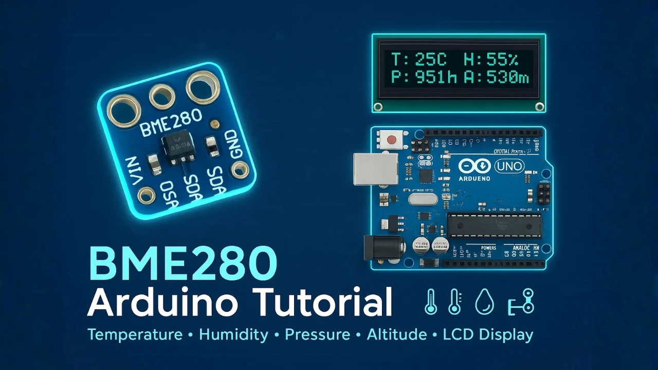
Arduino BME280 Tutorial: Wiring, Pinout, Code and LCD1602 Display Output
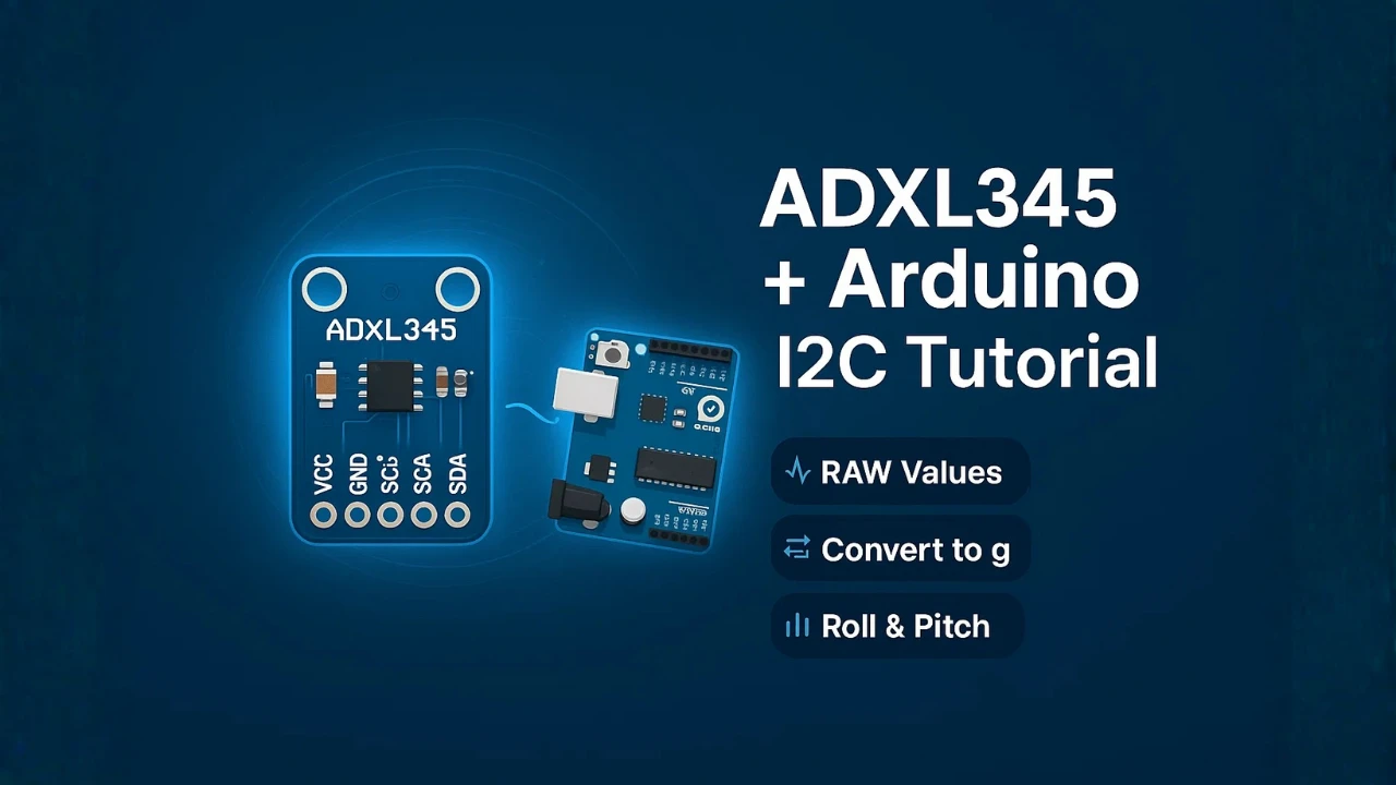
ADXL345 Arduino I2C Tutorial: Pinout, Wiring, Calibration, and Accelerometer Data Reading Explained
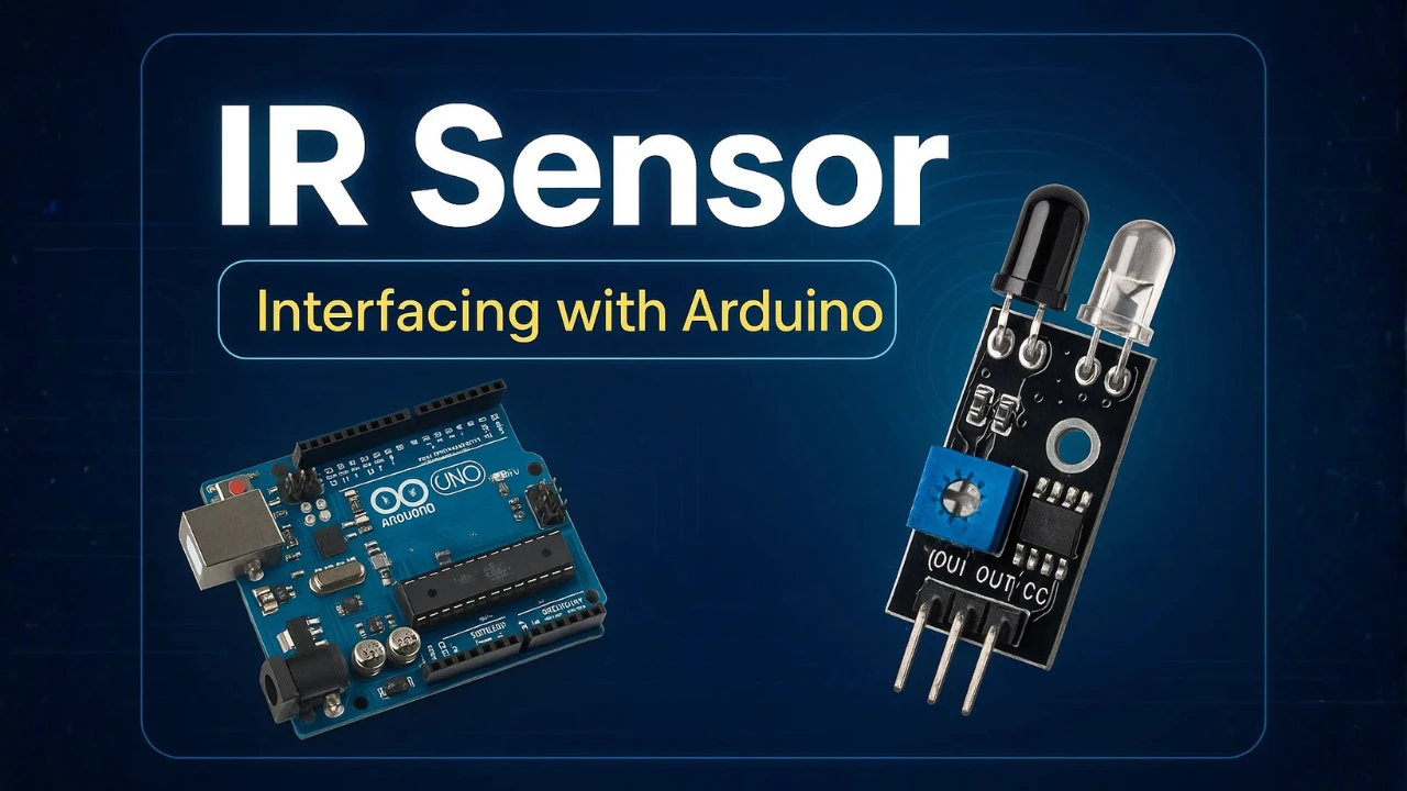
IR Sensor Arduino Tutorial: Interfacing, Calibration, Detection Modes, Codes & LCD1602 Display
Arduino PIR Motion Sensor Tutorial: Wiring, Modes, Sensitivity & Full Codes
Arduino AHT20 Project Download
Arduino AHT20 FAQs
Subscribe
Login
0 Comments
Newest
