Published: November 8, 2025
Last Updated: February 6, 2026
Last Updated: February 6, 2026
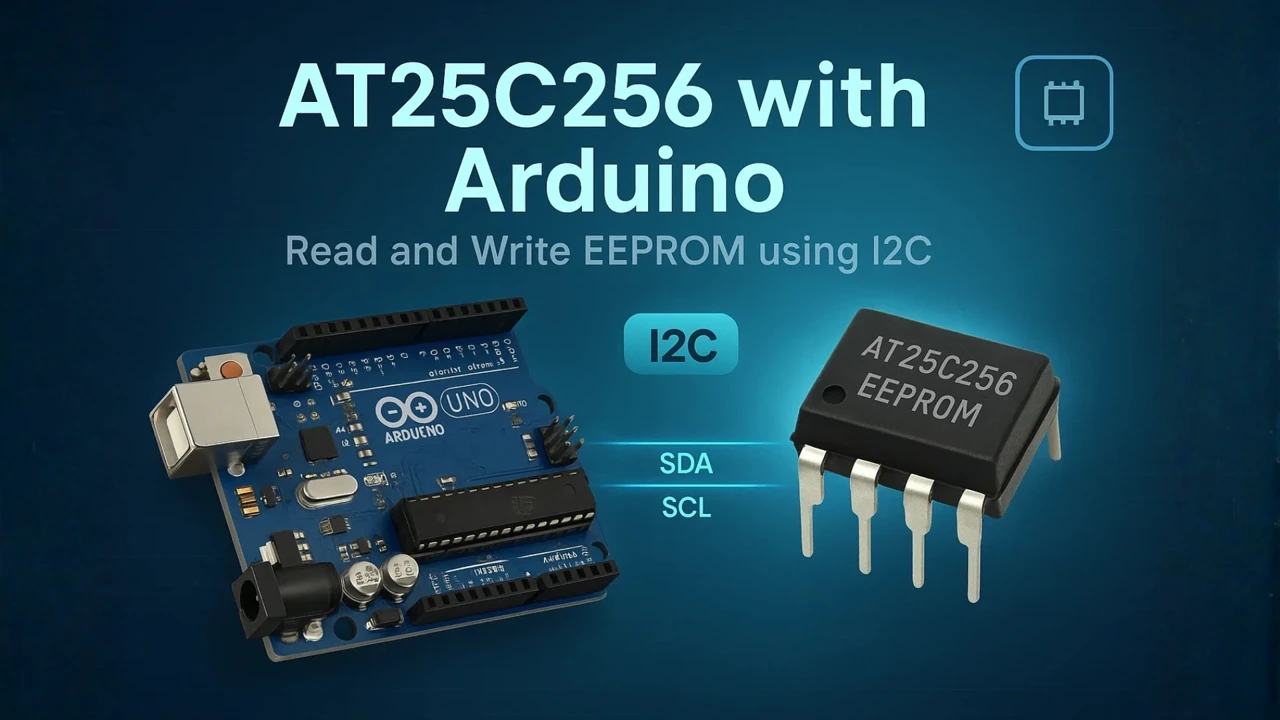
Interfacing AT25C256 EEPROM with Arduino using I2C
If you want to store data permanently on your Arduino projects, external EEPROMs like AT25C256 are a great choice. In this tutorial, we’ll learn how to interface AT25C256 with Arduino using I2C communication. You’ll see how to read and write bytes, and how to store numbers, floats, and even 16-bit or 32-bit hex values in the EEPROM memory.
We’ll start with a quick look at the AT25C256 specifications, understand its I2C communication, and then move on to the wiring diagram and complete Arduino code. By the end of this guide, you’ll be able to use AT25C256 EEPROM for data logging, sensor calibration, or configuration storage in your projects.
Prerequisites:
Along with some basic knowledge of Arduino, you should also take a look at the Arduino I2C Tutorial covered a while back. This will help you understand the concept with much more clarity.
Introduction to AT25C256 EEPROM
What is AT25C256?
The AT25C256 is a 256-kilobit serial EEPROM (Electrically Erasable Programmable Read-Only Memory) that stores data even when the power is turned off. It communicates using the I2C protocol, making it easy to connect with microcontrollers like Arduino using just two data lines – SDA and SCL.
This chip is ideal for saving small amounts of data such as sensor readings, configuration settings, or calibration values. Since it’s non-volatile memory, the data stays intact even after resetting or powering down the system.
Key Features and Specifications
Here are some of the main features of the AT25C256 EEPROM:
- Memory Size: 256 Kbits (32 KB total memory)
- Interface: I2C compatible serial communication
- Operating Voltage: 1.7V to 5.5V
- Page Write Size: 64 bytes per page
- Data Retention: Up to 100 years
- Endurance: Up to 1 million write/erase cycles per byte
- Speed: Up to 1 MHz (depending on voltage and mode)
- Operating Temperature: -40°C to +85°C
These specifications make it reliable for long-term use in data logging and embedded systems. Its low power consumption and fast write cycle ensure smooth operation even in battery-powered devices.
Why Use AT25C256 with Arduino?
There are several reasons why the AT25C256 pairs perfectly with Arduino:
- It provides non-volatile storage, allowing you to keep data even after the Arduino is powered off.
- It supports the I2C interface, which means you only need two wires for communication, freeing up other pins for sensors or peripherals.
- With 32 KB of memory, it can store thousands of readings or settings.
- It’s affordable, easy to use, and well-supported by Arduino libraries.
Understanding I2C Communication with AT25C256
How I2C Protocol Works
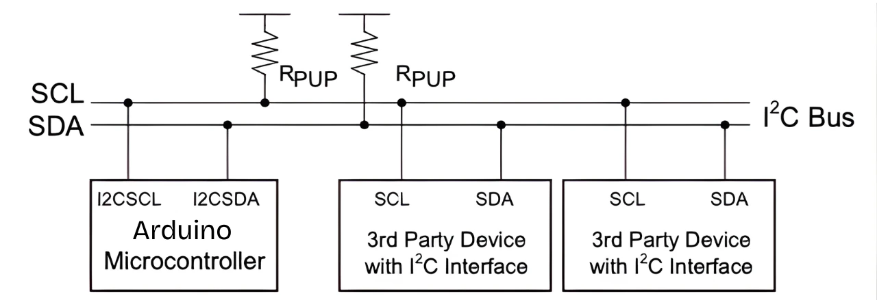
The I2C (Inter-Integrated Circuit) protocol is a simple and efficient two-wire communication system used to connect multiple devices using just two lines — SDA (Serial Data) and SCL (Serial Clock). One device acts as a master (in this case, the Arduino), and the others act as slaves (like the AT25C256).
When the Arduino wants to communicate, it sends a start condition followed by the slave address of the EEPROM. The AT25C256 recognizes its address, acknowledges it, and then listens for commands or data.
The I2C bus allows multiple devices to share the same lines, as long as each device has a unique address. This makes it easy to connect sensors, displays, and memory chips on the same I2C bus without using many GPIO pins.
I2C Address and Memory Organization
The AT25C256 has a 7-bit I2C slave address, usually in the range of 0x50 to 0x57, depending on how you connect the address pins A0, A1, and A2 to ground or VCC. Each address combination allows you to connect up to 8 EEPROM chips on the same I2C bus for increased storage.
Internally, the AT25C256 is organized into 32,768 bytes (or 32 KB) of memory. The memory is divided into pages, each containing 64 bytes. When writing data, you must stay within a single page; otherwise, data will wrap around and overwrite earlier bytes in that page.
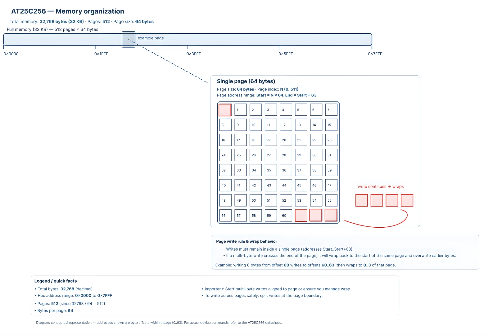
Here’s a quick breakdown:
- Total memory: 256 Kbits (32 KB)
- Page size: 64 bytes
- Number of pages: 512
- Address range: 0x0000 to 0x7FFF
So, every read or write command includes two address bytes to specify where the data should be stored or read from.
AT25C256 I2C Timing and Page Size
Timing is crucial when communicating over I2C, especially for write operations. The AT25C256 typically operates at up to 1 MHz clock speed, but most Arduino boards use 100 kHz (standard mode) or 400 kHz (fast mode).
After writing data to the EEPROM, there’s a small delay known as the write cycle time, usually around 5 milliseconds, during which the chip internally saves the data. During this time, it will not respond to any new commands.
The page size of 64 bytes means that you can write up to 64 bytes in one operation. If you attempt to write more than that, the data will wrap around within the same page. To ensure data integrity, it’s best to split large data blocks into multiple 64-byte pages.
In summary, the I2C communication with AT25C256 is simple yet powerful. With careful attention to addresses, timing, and page size, you can reliably store and retrieve data from this EEPROM using just two Arduino pins.
Circuit Diagram and Connections
Pinout of AT25C256
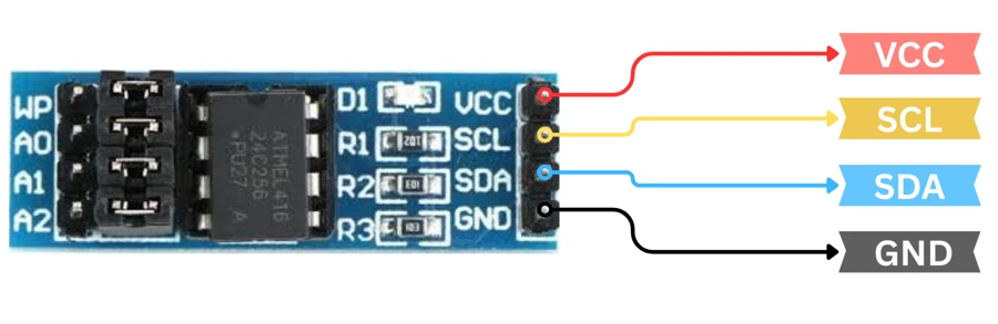
Before wiring the AT25C256 EEPROM, let’s understand its pin configuration. The chip usually comes in an 8-pin package, and each pin has a specific function.
The table below shows the pin description for each pin:
| Pin | Name | Description |
|---|---|---|
| 1 | A0 | Address bit 0 (used to set I2C address) |
| 2 | A1 | Address bit 1 (used to set I2C address) |
| 3 | A2 | Address bit 2 (used to set I2C address) |
| 4 | GND | Ground connection |
| 5 | SDA | Serial Data – I2C data line |
| 6 | SCL | Serial Clock – I2C clock line |
| 7 | WP | Write Protect – enables/disables write operations |
| 8 | VCC | Power supply pin (1.7V to 5.5V) |
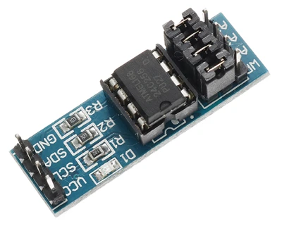
The A0, A1, and A2 pins allow you to select the device address when using multiple EEPROMs on the same I2C bus. The WP pin can be tied to GND to allow write operations or connected to VCC to protect the EEPROM from accidental writes.
Note: In the AT24C256 module shown in the image above, the pins A0, A1, A2 and WP are connected to the ground by default.
Connecting AT25C256 to Arduino
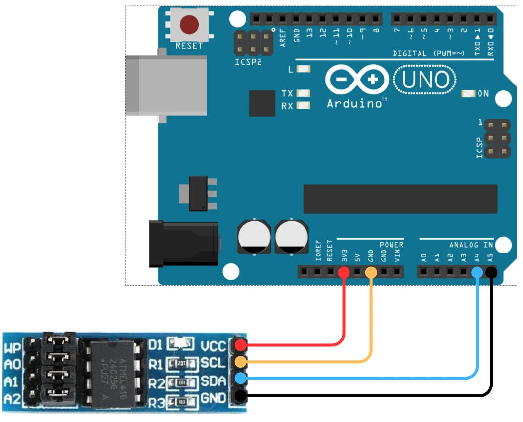
The wiring between the Arduino and AT25C256 is quite simple because of the I2C interface. You only need two communication lines, along with power and ground.
The image below shows the connection between Arduino and AT24C256 module.
Here’s the basic connection setup:
| AT25C256 Pin | Arduino Pin | Description |
|---|---|---|
| VCC | 3.3V | Power supply |
| GND | GND | Ground |
| SDA | A4 (on Uno/Nano) | I2C Data Line |
| SCL | A5 (on Uno/Nano) | I2C Clock Line |
| WP (GND on Module) | – | Disable write protection |
| A0, A1, A2 (GND on Module) | – | Sets base I2C address to 0x50 |
On Arduino Mega, the I2C pins are SDA = 20 and SCL = 21.
For Arduino Leonardo or Due, use the dedicated SDA/SCL pins marked on the board.
Finding the I2C Address of Your Module
Each I2C device has a unique 7-bit address that identifies it on the I2C bus. For most AT24C256 modules, this address is commonly 0x50, but it can vary depending on the manufacturer.
To find your Module’s I2C address, you can run a simple I2C scanner sketch on your Arduino:
#include <Wire.h>

void setup() {
  Wire.begin();
  Serial.begin(9600);
  Serial.println("Scanning for I2C devices...");
  for (byte i = 1; i < 127; i++) {
    Wire.beginTransmission(i);
    if (Wire.endTransmission() == 0) {
      Serial.print("I2C device found at address 0x");
      Serial.println(i, HEX);
    }
  }
}

void loop() {}Upload this code to your Arduino and open the Serial Monitor. You’ll see the detected I2C address printed there.
The image below shows the result of the I2C scanner code.
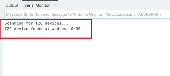
You can see the address 0x50 is detected by the scanner. We will use this address in our code when initializing the AT24C256 module.
Note: If no address is detected, check your wiring and ensure the SDA and SCL pins are correctly connected to your Arduino.
Power and Pull-Up Resistor Requirements
The AT25C256 works with a wide voltage range (1.7V to 5.5V), which means it can directly interface with both 3.3V and 5V Arduino boards.
The SDA and SCL lines require pull-up resistors (typically 4.7kΩ or 10kΩ) connected to the supply voltage (VCC). Some Arduino boards already include these resistors on the I2C lines, but if your circuit behaves unreliably, add external pull-ups for better stability.
Also, make sure to decouple the power supply using a small 0.1µF ceramic capacitor near the VCC and GND pins of the EEPROM. This helps filter noise and ensures stable operation.
In short, the AT25C256 requires very few components to operate with Arduino — just power, ground, two data lines, and optional pull-up resistors. Once connected properly, it’s ready for reliable data storage and retrieval.
Arduino Code to Read and Write Data
Once your AT25C256 EEPROM is properly connected to the Arduino, you can start communicating with it using the Wire library. This library handles all the I2C communication details for you, making the code simple and beginner-friendly.
In this section, we’ll go through how to write and read data from the AT25C256, starting from a single byte, and then moving on to multiple bytes.
Writing a Single Byte
To write a single byte to the EEPROM, you need to send three things over I2C:
- The device address (usually 0x50).
- The memory address where the data will be stored.
- The data byte itself.
Here’s a simple example:
#include <Wire.h>

#define EEPROM_I2C_ADDRESS 0x50  // AT25C256 base address

void setup() {
  Wire.begin();
  Serial.begin(9600);
  Serial.println("Writing single byte to AT25C256...");

  writeEEPROM(0x000A, 0x55); // Write 0x55 at memory address 0x000A
  delay(10); // Small delay for write cycle
  Serial.println("Write complete.");
}

void loop() {}

void writeEEPROM(unsigned int memAddress, byte data) {
  Wire.beginTransmission(EEPROM_I2C_ADDRESS);
  Wire.write((memAddress >> 8) & 0xFF);  // High byte of address
  Wire.write(memAddress & 0xFF);         // Low byte of address
  Wire.write(data);                      // Data byte
  Wire.endTransmission();
  delay(5); // Allow EEPROM to complete the write cycle
}Explanation of the code:
- Library include:
#include <Wire.h>— uses Arduino’s I²C library to communicate with the AT25C256 EEPROM. - Address define:
#define EEPROM_I2C_ADDRESS 0x50— sets the EEPROM’s 7-bit I²C address (base address). - setup():
- Starts I²C communication with
Wire.begin() - Starts serial communication for messages.
- Calls
writeEEPROM(0x000A, 0x55)to write the value0x55into EEPROM memory location0x000A. - Adds a small delay to ensure the write cycle completes.
- Starts I²C communication with
- loop():
Empty — because the operation is done once at startup. - writeEEPROM():
- Begins I²C transmission to EEPROM.
- Sends the 16-bit memory address in two parts (high and low bytes).
- Sends the data byte to be written.
- Ends transmission and waits 5 ms for the write to finish (EEPROM’s internal write time).
Output on the console
The image below shows the output of the above code on the Arduino Serial console.
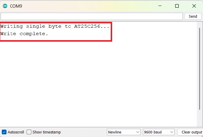
As you can see in the image, the data was written successfully to the EEPROM. This mean we can now proceed to read the data from the same memory location.
Reading a Single Byte
To Read from the EEPROM, you need to first send the memory address you want to read from, and then requesting one byte from the device.
Here’s how you can do that:
#include <Wire.h>

#define EEPROM_I2C_ADDRESS 0x50

void setup() {
  Wire.begin();
  Serial.begin(9600);

  byte data = readEEPROM(0x000A); // Read the byte from address 0x000A
  Serial.print("Data read from EEPROM: 0x");
  Serial.println(data, HEX);
}

void loop() {}

byte readEEPROM(unsigned int memAddress) {
  byte data = 0;
  Wire.beginTransmission(EEPROM_I2C_ADDRESS);
  Wire.write((memAddress >> 8) & 0xFF);
  Wire.write(memAddress & 0xFF);
  Wire.endTransmission();

  Wire.requestFrom(EEPROM_I2C_ADDRESS, 1);
  if (Wire.available()) data = Wire.read();
  return data;
}Explanation of the code:
- Library include:
#include <Wire.h>— uses Arduino’s I²C library to communicate with the AT25C256 EEPROM. - Address define:
#define EEPROM_I2C_ADDRESS 0x50— sets the EEPROM’s 7-bit I²C address (base address). - setup():
- Starts I²C communication with
Wire.begin() - Starts serial communication for messages.
- Calls
readEEPROM(0x000A)to read one byte from memory address0x000A. - Prints the read value in hexadecimal format to the Serial Monitor.
- Starts I²C communication with
- loop():
Empty — because the operation is done once at startup. - readEEPROM():
- Sends the 16-bit memory address (high byte + low byte) to the EEPROM so it knows which location to read.
- Ends the transmission.
- Requests 1 byte back from that memory address.
- Reads and returns the byte if available.
Output on the console
The image below shows the output of the above code on the Arduino Serial console.
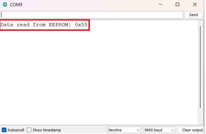
As you can see in the image, the data (0x55) was read back from the memory. This is the same data that we stored during the write operation.
Writing and Reading Multiple Bytes
The AT25C256 allows writing up to 64 bytes at once (one page). Writing more than 64 bytes in a single operation will cause data wrapping within that page.
Here’s how to write and read multiple bytes safely:
#include <Wire.h>

#define EEPROM_I2C_ADDRESS 0x50

void setup() {
  Wire.begin();
  Serial.begin(9600);

  byte writeData[] = {10, 20, 30, 40, 50};
  writeMultiple(0x0010, writeData, 5);
  delay(10);

  byte readData[5];
  readMultiple(0x0010, readData, 5);

  Serial.println("Data read from EEPROM:");
  for (int i = 0; i < 5; i++) {
    Serial.print(readData[i]);
    Serial.print(" ");
  }
  Serial.println();
}

void loop() {}

void writeMultiple(unsigned int memAddress, byte *data, int length) {
  Wire.beginTransmission(EEPROM_I2C_ADDRESS);
  Wire.write((memAddress >> 8) & 0xFF);
  Wire.write(memAddress & 0xFF);
  for (int i = 0; i < length; i++) {
    Wire.write(data[i]);
  }
  Wire.endTransmission();
  delay(5);
}

void readMultiple(unsigned int memAddress, byte *buffer, int length) {
  Wire.beginTransmission(EEPROM_I2C_ADDRESS);
  Wire.write((memAddress >> 8) & 0xFF);
  Wire.write(memAddress & 0xFF);
  Wire.endTransmission();

  Wire.requestFrom(EEPROM_I2C_ADDRESS, length);
  for (int i = 0; i < length && Wire.available(); i++) {
    buffer[i] = Wire.read();
  }
}This example writes an array of five numbers to EEPROM and then reads them back for verification. It’s the same principle used for storing sensor readings, calibration values, or any other structured data.
Output on the console
The image below shows the output of the above code on the Arduino Serial console.
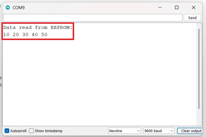
You can see in the image above, the 5 numbers (10, 20, 30, 40 and 50) were read back from the memory. This implies that we are able to write and read multiple data bytes from the AT24C256 memory.
Storing Different Data Types in AT25C256
The AT25C256 EEPROM can store any kind of data — not just simple bytes. You can easily save integers, floating point numbers, or even 16-bit and 32-bit hexadecimal values. However, since the EEPROM stores data in bytes, you need to break down complex data types into bytes before writing, and then rebuild them when reading.
In this section, we’ll see how to handle different data types properly using Arduino.
Store and Read Integer Values
An integer in Arduino usually takes 2 bytes (16 bits). So, to store it in the EEPROM, you can split it into two separate bytes and write them one after another.
Here’s how to do it:
#include <Wire.h>

#define EEPROM_I2C_ADDRESS 0x50

void setup() {
  Wire.begin();
  Serial.begin(9600);

  int number = 12345;
  writeInt(0x0020, number);
  delay(10);

  int readNumber = readInt(0x0020);
  Serial.print("Stored Integer: ");
  Serial.println(readNumber);
}

void loop() {}

void writeInt(unsigned int memAddress, int value) {
  byte highByte = (value >> 8) & 0xFF;
  byte lowByte = value & 0xFF;

  Wire.beginTransmission(EEPROM_I2C_ADDRESS);
  Wire.write((memAddress >> 8) & 0xFF);
  Wire.write(memAddress & 0xFF);
  Wire.write(highByte);
  Wire.write(lowByte);
  Wire.endTransmission();
  delay(5);
}

int readInt(unsigned int memAddress) {
  Wire.beginTransmission(EEPROM_I2C_ADDRESS);
  Wire.write((memAddress >> 8) & 0xFF);
  Wire.write(memAddress & 0xFF);
  Wire.endTransmission();

  Wire.requestFrom(EEPROM_I2C_ADDRESS, 2);
  byte highByte = Wire.read();
  byte lowByte = Wire.read();

  return (highByte << 8) | lowByte;
}Explanation of the code:
- Handling multi-byte data (integer):
Theintvariable is 16 bits (2 bytes) in size, therefore the code stores a 2-byte value. - Splitting and combining bytes:
writeInt()separates the integer into a high byte and low byte using bit shifting and masking.readInt()reads those two bytes back and reconstructs the original integer with(highByte << 8) | lowByte. - Two-byte transfer
The write function sends both bytes sequentially to consecutive EEPROM addresses.
The read function requests 2 bytes in one go usingWire.requestFrom(..., 2);.
Output on the console
The image below shows the output of the above code on the Arduino Serial console.

You can see in the image above, the integer value that we stored in the memory, is read back from the same location. This implies that we can store and read back the integer values from the AT24C256 EEPROM.
Store and Read Floating Point Numbers
A float in Arduino uses 4 bytes of memory. You can use a byte pointer to access each byte of the float and write them sequentially to the EEPROM.
Here’s how you can store and retrieve floating point values:
#include <Wire.h>

#define EEPROM_I2C_ADDRESS 0x50

void setup() {
  Wire.begin();
  Serial.begin(9600);

  float temperature = 36.78;
  writeFloat(0x0030, temperature);
  delay(10);

  float readTemp = readFloat(0x0030);
  Serial.print("Stored Float: ");
  Serial.println(readTemp, 2);
}

void loop() {}

void writeFloat(unsigned int memAddress, float value) {
  byte *data = (byte*)&value;
  Wire.beginTransmission(EEPROM_I2C_ADDRESS);
  Wire.write((memAddress >> 8) & 0xFF);
  Wire.write(memAddress & 0xFF);
  for (int i = 0; i < 4; i++) Wire.write(data[i]);
  Wire.endTransmission();
  delay(5);
}

float readFloat(unsigned int memAddress) {
  float value;
  byte *data = (byte*)&value;

  Wire.beginTransmission(EEPROM_I2C_ADDRESS);
  Wire.write((memAddress >> 8) & 0xFF);
  Wire.write(memAddress & 0xFF);
  Wire.endTransmission();

  Wire.requestFrom(EEPROM_I2C_ADDRESS, 4);
  for (int i = 0; i < 4; i++) data[i] = Wire.read();

  return value;
}Explanation of the code:
- Float data type:
Afloatin Arduino (AVR boards like Uno) is 32 bits = 4 bytes, so we need to handle four bytes instead of one or two. - Using pointers to access bytes:
byte *data = (byte*)&value;
This line takes the memory address of the float and treats it as a byte array, allowing access to its 4 individual bytes. - Looping through bytes:
Thefor (int i = 0; i < 4; i++)loop writes or reads each of the 4 bytes one by one to/from the EEPROM. - Reconstruction of float:
When reading, the bytes are copied back into the same memory area ((byte*)&value), so the float automatically gets reconstructed correctly.
Output on the console
The image below shows the output of the above code on the Arduino Serial console.
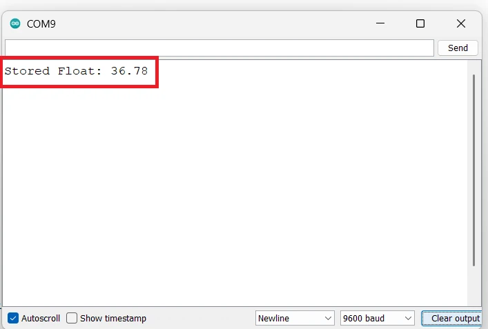
You can see in the image above, the float value that we stored in the memory, is read back from the same location. This implies that we can store and read back the float values from the AT24C256 EEPROM.
Store and Read 16-bit and 32-bit Hex Values
You might also need to store hexadecimal values, such as color codes, device IDs, or sensor readings. These can be 16-bit or 32-bit numbers. The approach is similar — break them into bytes before writing and combine them back while reading.
Example for 16-bit HEX:
// Function to write a 16-bit hexadecimal value
void writeHex16(unsigned int memAddress, unsigned int hexValue) {
  Wire.beginTransmission(EEPROM_I2C_ADDRESS);
  Wire.write((memAddress >> 8) & 0xFF);  // High byte of memory address
  Wire.write(memAddress & 0xFF);         // Low byte of memory address
  Wire.write((hexValue >> 8) & 0xFF);    // High byte of hex value
  Wire.write(hexValue & 0xFF);           // Low byte of hex value
  Wire.endTransmission();
  delay(5); // Wait for EEPROM to complete the write cycle
}

// Function to read a 16-bit hexadecimal value
unsigned int readHex16(unsigned int memAddress) {
  Wire.beginTransmission(EEPROM_I2C_ADDRESS);
  Wire.write((memAddress >> 8) & 0xFF);
  Wire.write(memAddress & 0xFF);
  Wire.endTransmission();

  Wire.requestFrom(EEPROM_I2C_ADDRESS, 2);
  byte high = 0, low = 0;
  if (Wire.available()) high = Wire.read();
  if (Wire.available()) low = Wire.read();

  return (high << 8) | low;
}Example for 32-bit HEX:
// Function to write a 32-bit hexadecimal value
void writeHex32(unsigned int memAddress, unsigned long hexValue) {
  Wire.beginTransmission(EEPROM_I2C_ADDRESS);
  Wire.write((memAddress >> 8) & 0xFF);   // High byte of memory address
  Wire.write(memAddress & 0xFF);          // Low byte of memory address
  Wire.write((hexValue >> 24) & 0xFF);    // Byte 3 (MSB)
  Wire.write((hexValue >> 16) & 0xFF);    // Byte 2
  Wire.write((hexValue >> 8) & 0xFF);     // Byte 1
  Wire.write(hexValue & 0xFF);            // Byte 0 (LSB)
  Wire.endTransmission();
  delay(5);  // Allow EEPROM write cycle to complete
}

// Function to read a 32-bit hexadecimal value
unsigned long readHex32(unsigned int memAddress) {
  Wire.beginTransmission(EEPROM_I2C_ADDRESS);
  Wire.write((memAddress >> 8) & 0xFF);   // High byte of memory address
  Wire.write(memAddress & 0xFF);          // Low byte of memory address
  Wire.endTransmission();

  Wire.requestFrom(EEPROM_I2C_ADDRESS, 4);  // Request 4 bytes
  unsigned long value = 0;
  for (int i = 0; i < 4; i++) {
    value = (value << 8) | Wire.read();     // Combine bytes into 32-bit value
  }
  return value;
}With these functions, you can easily handle hexadecimal values like 0x1A2B or 0xFF00AA55. This is very useful for sensor calibration data, unique IDs, or communication protocol parameters.
In summary, the AT25C256 EEPROM can handle any kind of data. Be it integers, floats, or hex values, as long as you split and reassemble them correctly. Using simple helper functions like these, your Arduino can store structured data permanently, making your projects more powerful and reliable.
Common Problems and Fixes
Even though the AT25C256 EEPROM is simple to use, a few issues can come up during testing or real-world use. Most of these problems are caused by wiring mistakes, timing delays, or incorrect handling of the I2C protocol.
Let’s look at some of the most common problems and their fixes.
EEPROM Not Responding on I2C
If the Arduino can’t detect the EEPROM during an I2C scan, or you get no data while reading, it usually means there’s a communication issue.
Possible Causes and Fixes:
- Incorrect Wiring: Double-check the SDA and SCL pins. On Arduino Uno/Nano, use A4 (SDA) and A5 (SCL). On Mega, use pins 20 and 21.
- No Pull-Up Resistors: I2C needs 4.7kΩ or 10kΩ pull-up resistors on SDA and SCL. Add them if missing.
- Wrong Device Address: The EEPROM’s I2C address depends on the A0, A1, and A2 pins. If all are tied to GND, the address is 0x50. Changing them changes the address.
- Power Issues: Make sure the EEPROM gets a stable 3.3V or 5V power supply. Use a 0.1µF capacitor across VCC and GND for noise filtering.
Running an I2C scanner sketch is a great first step to confirm whether the AT25C256 is detected.
Data Not Written or Corrupted
If your EEPROM doesn’t store the expected values, or the data appears corrupted, it often indicates an issue with timing or write cycles.
Possible Causes and Fixes:
- Missing Delay After Write: After writing data, the EEPROM needs time to complete the internal write cycle (about 5 ms). Always include a short
delay(5)after each write operation. - Crossing Page Boundaries: The AT25C256 writes data in 64-byte pages. If you write more than 64 bytes without handling page limits, the data wraps within the same page. Always write within page boundaries or split large data blocks.
- Write Protect Pin (WP): Ensure the WP pin is connected to GND. If it’s tied to VCC, the EEPROM becomes read-only, and write operations will fail silently.
- Power Interruptions: If power is lost during a write operation, data may become corrupted. Use stable power and avoid frequent writes in power-sensitive systems.
Wrong Data on Readback
Sometimes you might read back incorrect or random values, even when the write appears successful. This usually happens due to addressing mistakes or reading at the wrong memory location.
Possible Causes and Fixes:
- Incorrect Memory Address: Remember that AT25C256 uses two address bytes (high and low). Always send both bytes correctly before reading.
- Mismatched Data Length: When reading multiple bytes, ensure the same number of bytes are requested as were written.
- Improper Page Handling: If your data spans multiple pages but is written as a single block, only the first page may contain correct data. Split large datasets into page-sized writes.
- Electrical Noise: Long I2C wires or interference can cause random read errors. Keep SDA and SCL wires short and use a decoupling capacitor near the EEPROM.
If problems persist, try lowering the I2C speed to 100 kHz using:
Wire.setClock(100000);This often improves reliability in noisy environments or with long wire runs.
Applications of AT25C256 with Arduino
Data Logging and Sensor Storage
The AT25C256 EEPROM is ideal for data logging projects where you need to store sensor readings over time. For example, temperature, humidity, or pressure values from sensors can be recorded periodically and later analyzed. Since this memory is non-volatile, the stored data remains safe even after the Arduino is powered off. This makes it perfect for long-term data recording in IoT, agricultural, or environmental monitoring systems.
Configuration or Calibration Storage
In many embedded systems, you need to save calibration constants or user-defined configurations. The AT25C256 provides a convenient way to store such values permanently. For example, calibration offsets for sensors or motor speed settings can be saved once and reloaded automatically when the Arduino starts. This eliminates the need to manually re-enter data after every reset or power loss.
Offline Data Backup Systems
The AT25C256 can also be used as a local backup memory when your project works offline or without internet access. You can temporarily store critical data such as error logs, machine runtime information, or sensor history. Once the Arduino reconnects to a network or SD card, the stored information can be uploaded or processed further. This helps ensure data reliability even in cases of communication failures or power interruptions.
Conclusion
In this tutorial, you learned how to interface the AT25C256 EEPROM with an Arduino using the I2C protocol. We discussed the internal organization of the chip, its addressing method, and how to properly connect it to your Arduino board. You also explored different code examples to write and read data, including single bytes, multiple bytes, and various data types such as integers, floats, and both 16-bit and 32-bit hexadecimal values.
You now understand how to use the AT25C256 for data logging, configuration storage, and offline data backup in your Arduino projects. With this knowledge, you can easily expand your embedded systems to store important data reliably even when the power is off. This makes AT25C256 a great choice for practical, long-term data storage in any microcontroller-based application.
Browse More Arduino Tutorials
Arduino UART Tutorial: Step-by-Step Guide to Serial Communication
Arduino ADC and analogRead() Explained – Read Analog Voltage Easily

Complete Arduino I2C Tutorial with Examples: Wire Library & Projects

Mastering Arduino’s delayMicroseconds() Function: A Practical Guide
Arduino PWM and analogWrite() Explained: A Complete Beginner’s Guide
Arduino External Interrupts Guide: How to Use INT0 & INT1 Pins for Responsive Projects
How to Interface I2C LCD1602 Display with Arduino (With Custom Characters)
Arduino AT24C256 Project Download
Arduino AT24C256 I2C FAQs
Subscribe
Login
0 Comments
Newest
