Published: November 10, 2025
Last Updated: February 6, 2026
Last Updated: February 6, 2026
Interfacing W25Q SPI Flash Memory with Arduino (Complete Tutorial)
Flash memory plays a vital role in embedded systems where large, reliable, and fast data storage is needed. In this tutorial, we’ll learn how to interface W25Q SPI Flash memory with Arduino and use it to store, read, and manage data efficiently.
The W25Q series of SPI Flash memories, such as W25Q32, W25Q64, or W25Q128, are widely used for data logging, firmware updates, and external storage in IoT and microcontroller projects. They offer high speed, long endurance, and large capacity — far beyond what a typical Arduino’s EEPROM can handle.
We’ll begin by understanding what Flash memory is and how it differs from EEPROM. Then we’ll move to circuit connections, initialization code, and data storage examples. You’ll also learn how to store integers, floats, strings, and multi-byte values like 16-bit and 32-bit data types.

Table Of Contents
What is W25Q Flash Memory?
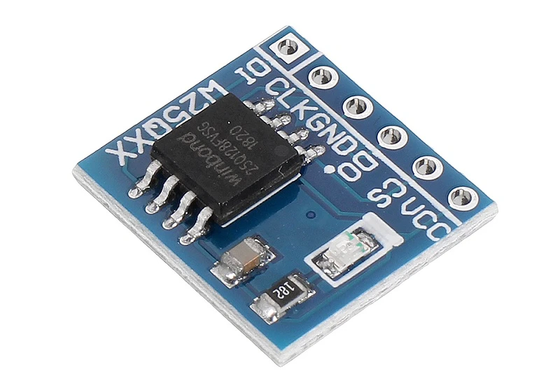
The W25Q Flash memory is a type of serial NOR Flash memory that communicates using the SPI (Serial Peripheral Interface) protocol. It is designed to store large amounts of data, such as program files, sensor logs, or configuration settings, outside the Arduino’s internal memory.
Manufactured by Winbond, the W25Q series comes in different storage capacities, commonly ranging from 1 Mbit to 256 Mbit (that’s up to 32 MB). Each chip can store thousands of data entries and still provide fast read and write access.
Unlike EEPROM, which stores smaller chunks of data, W25Q Flash can handle bigger data blocks efficiently, making it ideal for applications that require high-speed and high-capacity non-volatile storage. It retains data even when the power is turned off, ensuring your stored information is always safe.
Why Use Flash Memory with Arduino?
Arduino boards have limited built-in storage, which often isn’t enough for real-world applications like data logging, audio storage, or large firmware handling. Using a W25Q Flash memory chip adds extra space that works almost like an external hard drive for your microcontroller.
Here are a few key reasons to use it:
- Expand storage capacity without changing the board.
- Store and retrieve data quickly using the SPI interface.
- Log large datasets such as temperature, sensor readings, or GPS data.
- Keep data safe permanently, even after power loss.
- Use it for firmware updates or to store media like bitmaps and icons.
With the right SPI Flash library, it’s easy to integrate and control W25Q Flash using just a few lines of Arduino code.
Key Features of the W25Q Series
The W25Q series offers a great mix of performance, capacity, and reliability, making it one of the most popular flash memory choices for embedded systems.
Here are the main features you should know:
- Wide storage range: From 1 Mbit (128 KB) up to 256 Mbit (32 MB).
- SPI communication: Works over 4-wire SPI and supports Dual and Quad SPI for faster transfers.
- Fast read speeds: Up to 104 MHz, allowing quick data access.
- Sector and block erase: Supports 4 KB, 32 KB, and 64 KB erase sizes for flexible memory management.
- Low power consumption: Perfect for battery-powered devices.
- Long data retention: Can retain data for over 20 years.
- High endurance: Typically rated for 100,000 write/erase cycles.
These features make the W25Q Flash family a dependable choice for Arduino data storage projects, IoT systems, and embedded applications that need durable, high-capacity memory.
Difference Between NOR and NAND Flash Memory
Flash memory comes in two main types, NOR Flash and NAND Flash. Both are non-volatile memory technologies, meaning they store data even when the power is off, but they work in different ways and serve different purposes. Understanding the difference between the two will help you choose the right one for your Arduino or embedded project.
What is NOR Flash Memory?
NOR Flash memory is designed for fast random access and direct code execution. It connects every memory cell in parallel, allowing data to be read directly from any address, much like traditional RAM.
This architecture makes NOR Flash perfect for storing and executing firmware, bootloaders, or microcontroller programs. You can read or execute instructions directly from the Flash chip without copying them into RAM first.
Key points about NOR Flash:
- Provides random read access to any memory address.
- Ideal for storing executable code or small configuration data.
- Offers excellent reliability and long data retention.
- However, write and erase operations are slower, and the cost per bit is higher.
The W25Q series you’re using with Arduino is a NOR Flash memory, which makes it reliable for both data storage and program storage.
What is NAND Flash Memory?
NAND Flash memory is optimized for high-density data storage and fast sequential read/write operations. Unlike NOR Flash, its memory cells are connected in series, which makes it more compact and cheaper per bit.
This structure makes NAND Flash ideal for mass storage applications, such as SD cards, USB drives, and solid-state drives (SSDs). However, it cannot execute code directly and requires a controller or file system to manage data blocks.
Key points about NAND Flash:
- Provides fast sequential access, best for bulk data storage.
- Can store large files efficiently (images, audio, logs, etc.).
- Cheaper and denser than NOR Flash.
- Needs error correction (ECC) due to higher bit error rates.
- Not suitable for direct code execution from memory.
NOR vs NAND Flash – Key Differences
| Feature | NOR Flash | NAND Flash |
|---|---|---|
| Architecture | Parallel cell connection | Serial cell connection |
| Access Type | Random access | Sequential access |
| Speed (Read) | Faster for small reads | Faster for large data blocks |
| Write/Erase Speed | Slower | Faster |
| Density (Storage Size) | Lower | Higher |
| Cost per Bit | Higher | Lower |
| Use Case | Firmware, code storage, parameters | Bulk data storage, media files |
| Reliability | Very high | Moderate, needs ECC |
| Code Execution | Can execute directly (XIP) | Cannot execute directly |
When to Use NOR or NAND Flash in Your Projects
Choosing between NOR and NAND Flash depends on what kind of data you plan to store and how you’ll access it.
- Use NOR Flash (like W25Q) when you need:
- Reliable non-volatile storage for configuration data or firmware.
- Fast and easy access to small chunks of data.
- Support for code execution directly from Flash (XIP).
- Use NAND Flash when you need:
- Large data storage for files, logs, or multimedia.
- High-speed sequential read/write performance.
- Cost-effective memory for bulk data storage in big projects.
W25Q Flash Memory vs EEPROM
Both W25Q Flash memory and EEPROM are non-volatile storage devices used in embedded systems to retain data even after power loss. However, they differ in speed, capacity, and data handling methods. Understanding these differences will help you choose the best one for your Arduino project.
Advantages of Flash Memory Over EEPROM
The W25Q Flash memory offers several advantages compared to traditional EEPROM, especially when working with large data or fast applications.
Here are the main benefits:
- Much Higher Storage Capacity
Flash memory chips like the W25Q64 (8 MB) or W25Q128 (16 MB) can store far more data than EEPROMs, which typically range from just a few kilobytes to a few megabytes. - Faster Read and Write Speeds
Flash memory uses the SPI interface, which allows quick data transfer and fast random access. This makes it ideal for logging high-speed sensor data or handling multimedia files. - Lower Cost per Bit
For large storage needs, Flash memory is more cost-effective than EEPROM because it provides a much higher density at a lower price. - Block Erase Capability
W25Q Flash allows you to erase memory in blocks or sectors (4 KB, 32 KB, 64 KB), making data management more flexible compared to EEPROM, which usually handles data byte by byte. - Supports Firmware and Data Storage
NOR Flash memory like W25Q can store firmware, bootloaders, or configuration data and even execute code directly from the Flash, which EEPROM cannot do. - Longer Data Retention
Flash memory typically retains data for 20 years or more, ensuring long-term reliability for critical applications.
Limitations of Flash Memory Compared to EEPROM
While Flash memory has many strengths, it also has a few drawbacks that are worth noting before you use it in your project.
- Complex Write and Erase Process
Unlike EEPROM, which can modify a single byte, Flash memory must erase an entire sector before writing new data. This can make frequent small writes less efficient. - Limited Write Endurance
Flash memory usually supports about 100,000 write/erase cycles, whereas EEPROM can often handle up to 1 million cycles. For projects requiring constant data updates, EEPROM may last longer. - More Complicated to Interface
EEPROMs often use I2C or SPI protocols with simpler libraries, while Flash memory requires managing addresses, sectors, and pages, which can be a bit more advanced. - Larger Code Footprint
Because Flash memory needs extra logic for reading, writing, and erasing, it may require more code space in your Arduino sketch.
Despite these limitations, Flash memory still wins in most medium to large-scale data storage applications.
Which One Should You Choose for Your Arduino Project?
The choice between W25Q Flash memory and EEPROM depends mainly on how much data you need to store and how frequently you plan to update it.
Choose W25Q Flash Memory if:
- You need large storage capacity (megabytes instead of kilobytes).
- You want fast read and write speeds.
- You’re storing firmware, images, or sensor logs.
- You prefer a cost-effective and scalable solution.
Choose EEPROM if:
- You only need to store small configuration data (like settings or calibration values).
- Your data is updated frequently but stored in small quantities.
- You want simpler code and easy interfacing with I2C or SPI.
Circuit Diagram and Connections
In this section, we’ll go through the W25Q module’s Pinout, wiring connection with Arduino and components requirement for this project.
W25Q Flash Pinout
Before wiring the W25Q Flash with Arduino, let’s understand its pin configuration. The chip usually comes in an 8-pin package, and each pin has a specific function.
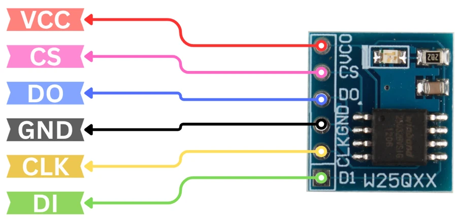
The table below shows the pin description for each pin:
| Pin Label | Description | Function |
|---|---|---|
| VCC | Power Supply | Connect to 3.3V |
| CS | Chip Select | Selects the flash chip (active low) |
| DO | Data Out (MISO) | Master In Slave Out — data output from flash |
| GND | Ground | Connect to system ground |
| CLK | Serial Clock (SCK) | SPI clock input |
| DI | Data In (MOSI) | Master Out Slave In — data input to flash |
Circuit Diagram and Connections
The W25Q Flash memory communicates with Arduino using SPI pins, which vary slightly depending on the Arduino board you are using (UNO, Nano, Mega, etc.).
The image below shows how the module is connected to Arduino UNO.
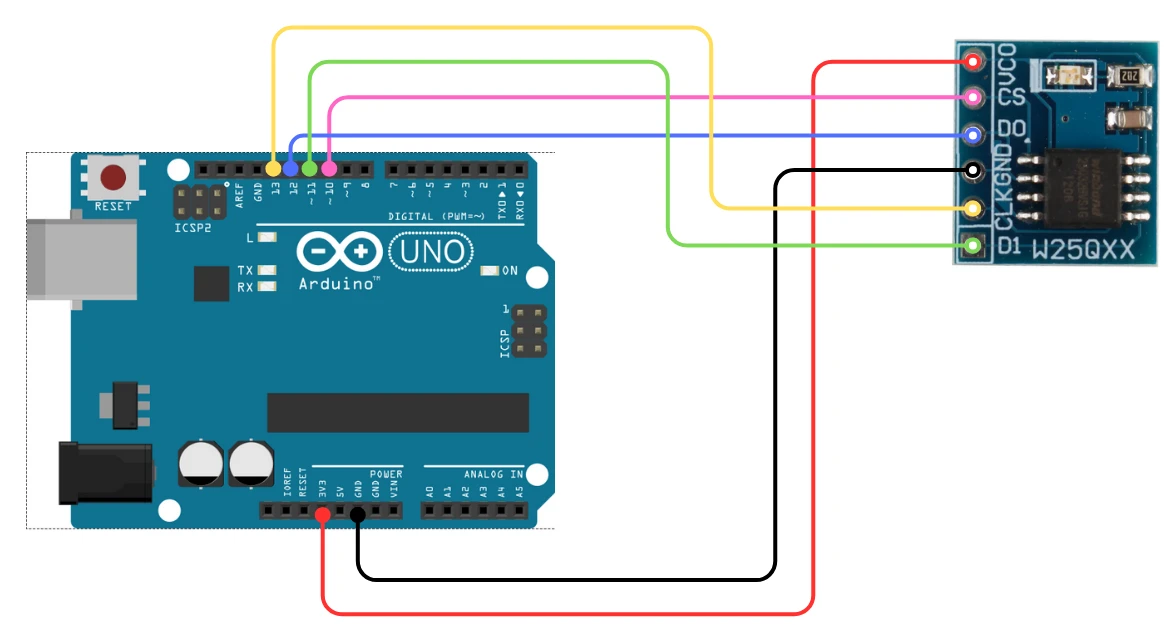
Here’s the standard SPI connection for Arduino UNO and similar boards:
| W25Q Flash Pin | Arduino UNO Pin | Function |
|---|---|---|
| CS (Chip Select) | D10 | Selects the SPI device |
| DO (MISO) | D12 | Master In Slave Out |
| DI (MOSI) | D11 | Master Out Slave In |
| CLK (SCK) | D13 | SPI Clock |
| GND | GND | Ground |
| VCC | 3.3V | Power supply |
| HOLD | 3.3V (Pull-Up) | Hold function, tie to VCC |
| WP (Write Protect) | 3.3V (Pull-Up) | Write Protect, tie to VCC |
Note:
The W25Q operates at 3.3V, so make sure not to connect it directly to 5V pins. If you are using a 5V Arduino, you can use logic level shifters or a voltage divider for the SPI lines.
Required Components
To interface the W25Q Flash memory with Arduino, you’ll need the following components:
- 1 × Arduino board (UNO, Nano, or Mega)
- 1 × W25Q Flash memory chip or module (such as W25Q32, W25Q64, or W25Q128)
- Jumper wires (preferably male-to-female)
- Breadboard (optional for easy connections)
- Logic level shifter (if using a 5V Arduino)
Interfacing W25Q Flash Memory with Arduino
Interfacing a W25Q SPI Flash memory with Arduino is simple and efficient because it uses the Serial Peripheral Interface (SPI) protocol. In this section, we’ll go through the basic setup code to initialize and detect the Flash chip.
Once connected, your Arduino will be able to read, write, and erase data on the Flash chip using just a few library functions.
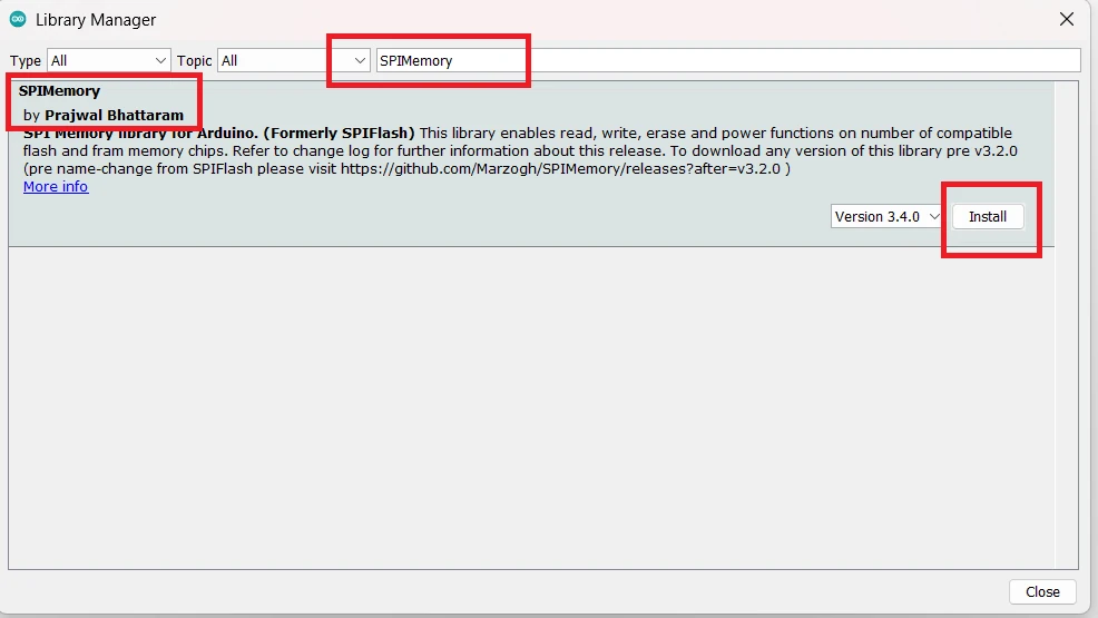
Installing the SPI Flash Library
To communicate with the W25Q Flash memory, you need a reliable library that handles the SPI protocol and Flash operations such as read, write, and erase.
The recommended library is “SPIMemory” by Pralwal Bhattaram, which is an improved and actively maintained version of the original Marzogh library.
Here’s how to install it:
- Open your Arduino IDE.
- Go to Sketch → Include Library → Manage Libraries…
- In the search bar, type “SPIMemory”.
- Select “SPIMemory” by Pralwal Bhattaram and click Install.
Basic Code for Initialization and Chip Detection
After wiring and installing the library, you can use the following code to initialize the Flash chip and check if it’s detected correctly.
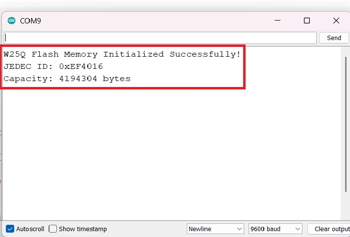
Every Flash memory chip has a unique JEDEC ID — a combination of three bytes that identify the manufacturer, memory type, and capacity.
When you initialize the Flash chip using the library, it automatically reads this ID and calculates the memory size for you.
For example:
- W25Q32 → 0xEF4016 → 4 MB
- W25Q64 → 0xEF4017 → 8 MB
- W25Q128 → 0xEF4018 → 16 MB
- W25Q256 → 0xEF4019 → 32 MB
#include <SPIMemory.h>

SPIFlash flash;  // Create flash object

void setup() {
  Serial.begin(9600);
  while (!Serial);

  if (flash.begin()) {
    Serial.println("W25Q Flash Memory Initialized Successfully!");
    Serial.print("JEDEC ID: 0x");
    Serial.println(flash.getJEDECID(), HEX);
    Serial.print("Capacity: ");
    Serial.print(flash.getCapacity());
    Serial.println(" bytes");
  } else {
    Serial.println("Flash Memory Initialization Failed!");
  }
}

void loop() {
  // Nothing here yet
}
Explanation:
flash.begin()initializes the SPI communication with the Flash chip.getJEDECID()reads the unique device ID, confirming correct connection.getCapacity()returns the total memory capacity of the Flash chip in bytes.
Output:
The image below shows the output of the Read ID code.
Writing and Reading Data from W25Q Flash
Once the W25Q Flash memory is initialized, we can use it to store and retrieve data of different types.
The SPIMemory library provides convenient functions to read and write various data types such as integers, floats, 16-bit and 32-bit values, and even strings.
Before diving into the examples, there are two important things to remember:
- Flash memory must be erased before writing new data.
This is because flash cells can only switch bits from1to0. To set them all back to1, you must erase the sector. That’s why we use theeraseSector()function before every write operation. - Always check if the write was successful.
The library’s write functions return a boolean value —truemeans the data was written successfully.
That’s why theSerial.print()statement is placed inside theifcondition, to only show a success message if the operation actually worked.
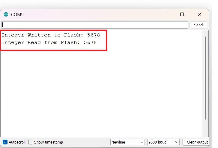
Store and Read Integer Data
This example demonstrates how to store and read an integer value in the flash memory.
#include <SPIMemory.h>
SPIFlash flash;

void setup() {
  Serial.begin(9600);
  flash.begin();

  int address = 0;
  int dataToWrite = 5678;
  int dataRead = 0;

  // Step 1: Erase the sector before writing
  // This ensures the memory area is clean and ready for new data
  flash.eraseSector(address);

  // Step 2: Write integer data to flash
  if (flash.writeShort(address, dataToWrite) == true) {
    Serial.print("Integer Written to Flash: ");
    Serial.println(dataToWrite);
  } else Serial.println("Failed to Write Data");

  // Step 3: Read back the integer from flash
  dataRead = flash.readShort(address);
  Serial.print("Integer Read from Flash: ");
  Serial.println(dataRead);
}

void loop() {}
Explanation:
- The function
writeShort()writes a 2-byte integer to the flash at the specified address. - The sector is erased first using
eraseSector(). Without erasing, writing new data might fail or cause corrupted values. - The
ifcondition ensures that “Integer Written to Flash” is printed only if the operation was successful. - The value is then read back using
readShort()and displayed on the Serial Monitor.
Output:
The image below shows the output of the Reading Integer Code.
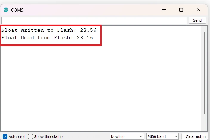
Store and Read Float Data
The following code shows how to work with floating-point numbers, which are useful for storing decimal values such as temperature or voltage.
#include <SPIMemory.h>
SPIFlash flash;

void setup() {
  Serial.begin(9600);
  flash.begin();

  int address = 0;
  float dataToWrite = 23.56;
  float dataRead = 0.0;

  // Erase the sector before writing
  flash.eraseSector(address);

  // Write float value to flash
  if (flash.writeFloat(address, dataToWrite) == true) {
    Serial.print("Float Written to Flash: ");
    Serial.println(dataToWrite);
  } else Serial.println("Failed to Write Float");

  // Read float value back
  dataRead = flash.readFloat(address);
  Serial.print("Float Read from Flash: ");
  Serial.println(dataRead, 2);
}

void loop() {}
Explanation:
- The function
writeFloat()handles the 4-byte float type automatically. eraseSector()ensures the memory space is cleared before new data is stored.- The data is then read back using
readFloat(). - The second argument in
Serial.println(dataRead, 2)controls how many decimal places to display.
Output:
The image below shows the output of the Reading Float Code.
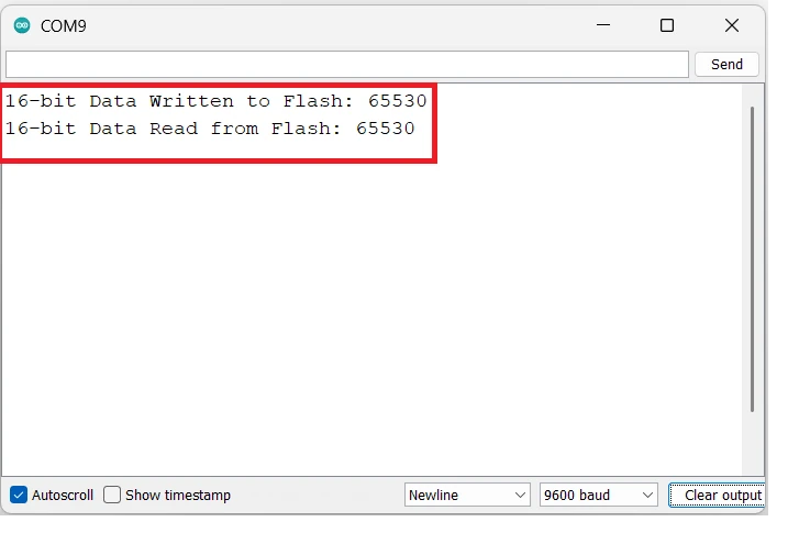
Store and Read 16-bit Data
This example shows how to handle 16-bit (2-byte) values such as ADC readings or sensor states.
#include <SPIMemory.h>
SPIFlash flash;

void setup() {
  Serial.begin(9600);
  flash.begin();

  int address = 0;
  uint16_t dataToWrite = 65530;
  uint16_t dataRead = 0;

  flash.eraseSector(address);

  if (flash.writeWord(address, dataToWrite) == true) {
    Serial.print("16-bit Data Written to Flash: ");
    Serial.println(dataToWrite);
  } else Serial.println("Failed to Write 16-bit Data");

  dataRead = flash.readWord(address);
  Serial.print("16-bit Data Read from Flash: ");
  Serial.println(dataRead);
}

void loop() {}
Explanation:
writeWord()andreadWord()are used for 16-bit unsigned integers.- This kind of data type is perfect when you need to store compact sensor values.
- Just like before, the erase operation ensures the new value overwrites correctly.
Output:
The image below shows the output of the Reading 16Bit values.
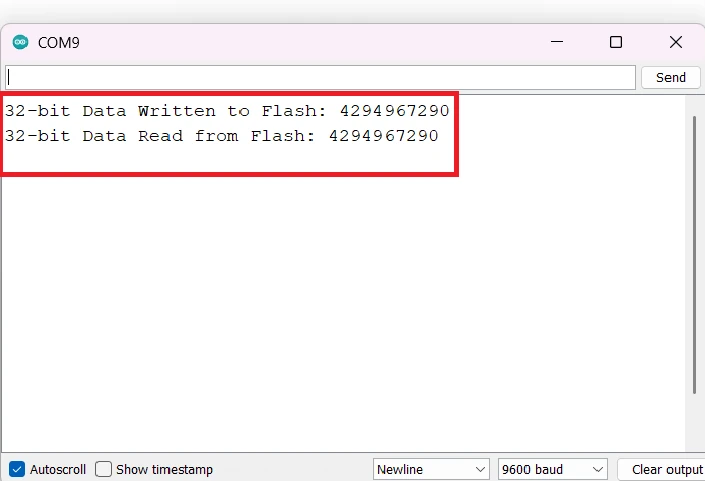
Store and Read 32-bit Data
For larger numeric values (like timestamps, counters, or IDs), use the 32-bit read and write functions.
#include <SPIMemory.h>
SPIFlash flash;

void setup() {
  Serial.begin(9600);
  flash.begin();

  int address = 0;
  uint32_t dataToWrite = 4294967290;
  uint32_t dataRead = 0;

  flash.eraseSector(address);

  if (flash.writeLong(address, dataToWrite) == true) {
    Serial.print("32-bit Data Written to Flash: ");
    Serial.println(dataToWrite);
  } else Serial.println("Failed to Write 32-bit Data");

  dataRead = flash.readLong(address);
  Serial.print("32-bit Data Read from Flash: ");
  Serial.println(dataRead);
}

void loop() {}
Explanation:
- The function
writeLong()writes 4 bytes (32 bits) of data into flash memory. - As before,
eraseSector()ensures the section of memory is empty. - The
ifcondition ensures only a successful operation prints the confirmation. - The same address is used for both write and read operations.
Output:
The image below shows the output of the Reading 32Bit values.
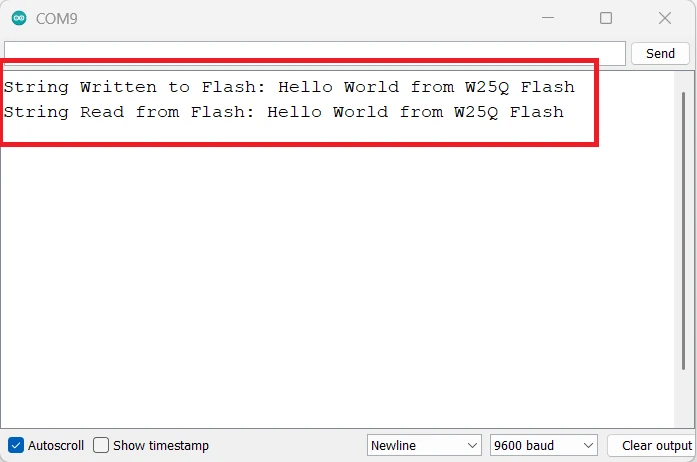
Store and Read String
Text data like names, messages, or configuration strings can also be stored using writeStr() and readStr().
#include <SPIMemory.h>
SPIFlash flash;

void setup() {
  Serial.begin(9600);
  flash.begin();

  int address = 0;
  String dataToWrite = "Hello World from W25Q Flash";
  String dataRead;


  flash.eraseSector(address);

  if (flash.writeStr(address, dataToWrite) == true) {
    Serial.print("String Written to Flash: ");
    Serial.println(dataToWrite);
  } else Serial.println("Failed to Write String");

  flash.readStr(address, dataRead);
  Serial.print("String Read from Flash: ");
  Serial.println(dataRead);
}

void loop() {}Explanation:
- Strings are stored as arrays of characters.
writeStr()writes each character sequentially into flash memory.readStr()retrieves the string and stores it into a character buffer (dataRead).- The
sizeof(dataRead)ensures we don’t read beyond the buffer size. - Again,
eraseSector()clears the memory area before writing.
Output:
The image below shows the output of the Reading String.
Common Problems and Fixes
When working with W25Q Flash memory and Arduino, you might occasionally face issues like the chip not being detected, incorrect data being read, or unstable SPI communication. These are usually caused by wiring mistakes, timing mismatches, or incorrect library configurations.
Let’s go through some common problems and their practical fixes.
Flash Memory Not Detected
Possible Causes and Fixes:
- Check SPI Connections:
Make sure that MOSI, MISO, CLK, and CS pins are correctly connected to your Arduino. Even one wrong wire can stop communication. - Verify Chip Select (CS) Pin:
The CS pin defined in your sketch must match the one actually connected to your board. For example, if your CS pin is connected to D10, define it asSPIFlash flash(10);. - Ensure Proper Power Supply:
The W25Q Flash chip requires 3.3V power. Supplying 5V may damage it, while insufficient current can make it unstable. - Check Pull-up Resistors:
In some setups, adding a 10kΩ pull-up resistor to the CS line can help ensure stable initialization. - Try Slower SPI Speed:
If the chip still doesn’t respond, reduce the SPI clock speed by editing the library or using a software SPI approach.
Incorrect Data Written or Read
Sometimes you might notice that the data read back from the Flash memory doesn’t match what you wrote.
Possible Causes and Fixes:
- Incorrect Addressing:
Flash memory is addressed by bytes, so ensure your address increments properly when writing multiple data blocks. - Missing Erase Command:
You must erase a sector before writing new data to it. If not, residual bits may cause corrupted reads. - Improper Data Type Handling:
When writing and reading variables likefloatoruint32_t, make sure to use the correct functions (writeFloat(),readFloat(), etc.). - Memory Overflow:
Ensure the data being written does not exceed the Flash chip’s capacity. Check memory boundaries usinggetCapacity(). - Incomplete Writes:
Avoid writing too frequently without delays — the chip needs some time to complete internal write cycles.
Communication Errors Over SPI
Possible Causes and Fixes:
- Loose Jumper Wires:
Loose or long wires can cause noise and data corruption. Keep SPI connections short and secure. - Voltage Level Mismatch:
If you’re using a 5V Arduino (like Uno or Nano), use a logic level shifter to step down signals to 3.3V. - Multiple SPI Devices:
If you have multiple devices on the SPI bus (like an SD card or OLED), make sure each device has its own CS pin and that they’re not active at the same time. - Library Conflicts:
Some other SPI-based libraries may interfere. Try disabling unused SPI devices during Flash testing. - Hardware Defects:
Rarely, a faulty Flash chip can also cause erratic behavior — try replacing it to confirm.
Applications of W25Q Flash Memory with Arduino
The W25Q series Flash memory is a powerful addition to any Arduino project that needs large, non-volatile data storage.
Unlike EEPROMs, which offer limited capacity, W25Q Flash chips can store megabytes of data while maintaining fast read and write speeds.
Let’s look at some of the most common and useful applications of W25Q Flash memory with Arduino.
Data Logging and Sensor Storage
One of the most popular uses of W25Q Flash memory is in data logging applications.
If your project collects sensor readings — like temperature, humidity, or motion data — the W25Q chip allows you to store a massive amount of readings without worrying about limited write cycles or small memory space.
For example, you can:
- Continuously log environmental sensor data for weeks or months.
- Store IoT readings when Wi-Fi is unavailable and upload them later.
- Keep a backup of calibration values or event logs in case of power loss.
With its fast sequential write capability, the W25Q can handle continuous data streams efficiently, making it ideal for long-term data collection projects.
Firmware Updates and Bootloaders
Another advanced use case is firmware storage and bootloading.
The W25Q Flash chip can act as an external storage device for your program code, allowing Over-the-Air (OTA) updates or manual firmware upgrades without needing a PC connection.
You can:
- Store multiple firmware versions and switch between them as needed.
- Implement bootloaders that read the main code from Flash and load it into the microcontroller.
- Use it as an external memory for larger projects that exceed the Arduino’s built-in flash size.
This feature is especially valuable in industrial IoT systems and embedded devices that require reliable field updates.
Storing Images, Audio, or Configuration Files
W25Q Flash memory is also perfect for storing media and configuration data.
Many graphical projects use it to store bitmaps, icons, fonts, or even short audio clips that can be accessed quickly during runtime.
Here are some examples:
- Storing GUI assets for TFT or OLED displays.
- Saving audio samples for alarms, tones, or notifications.
- Keeping user configuration files or Wi-Fi credentials in binary format.
Since Flash memory allows random access reading, you can fetch only the required bytes instead of loading everything at once — saving both time and RAM space.
With these capabilities, W25Q Flash memory becomes an essential component in IoT projects, smart devices, and multimedia systems, giving you both flexibility and high storage capacity at a low cost.
Conclusion
In this tutorial, we explored how to interface the W25Q Flash memory with an Arduino to achieve reliable operation across its entire memory range. You learned the fundamental principles behind Flash memory, how it differs from EEPROM in structure and performance, and the key distinctions between NOR and NAND Flash technologies. This understanding helps in selecting the right type of non-volatile memory for different embedded applications.
We also covered the complete setup process, including connecting the W25Q module to Arduino and installing the SPIMemory library by Pralwal Bhattaram. Through practical examples, you learned how to initialize the Flash chip, write and read various data types — such as integers, floating-point values, 16-bit and 32-bit variables, and strings — while ensuring proper memory addressing and data integrity. Additionally, we implemented automatic memory size detection to make the project compatible with different W25Q variants.
Finally, the tutorial demonstrated effective troubleshooting techniques for common issues such as detection failures, SPI communication errors, and data corruption. With these concepts in place, you can now confidently use the W25Q Flash for data logging, firmware updates, or configuration and media storage in your embedded projects, making your Arduino-based systems more flexible and powerful.
Browse More Arduino Tutorials
Arduino UART Tutorial: Step-by-Step Guide to Serial Communication
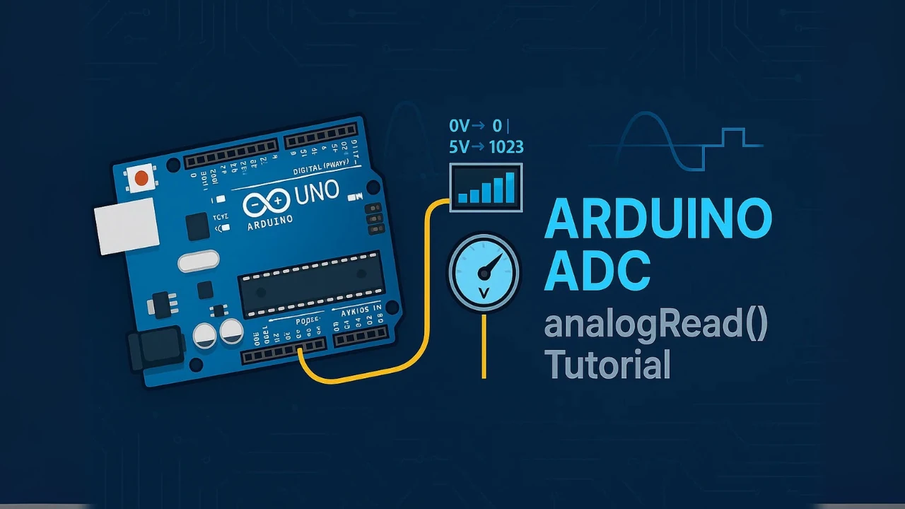
Arduino ADC and analogRead() Explained – Read Analog Voltage Easily

Complete Arduino I2C Tutorial with Examples: Wire Library & Projects

Mastering Arduino’s delayMicroseconds() Function: A Practical Guide
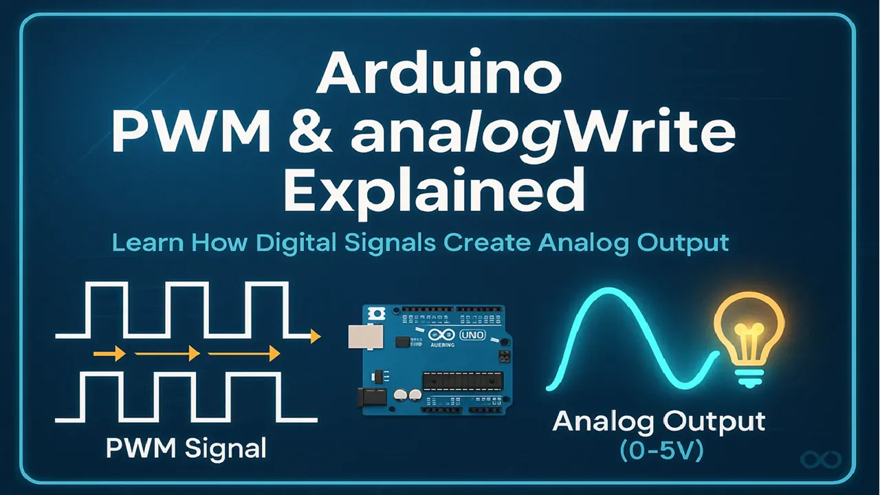
Arduino PWM and analogWrite() Explained: A Complete Beginner’s Guide
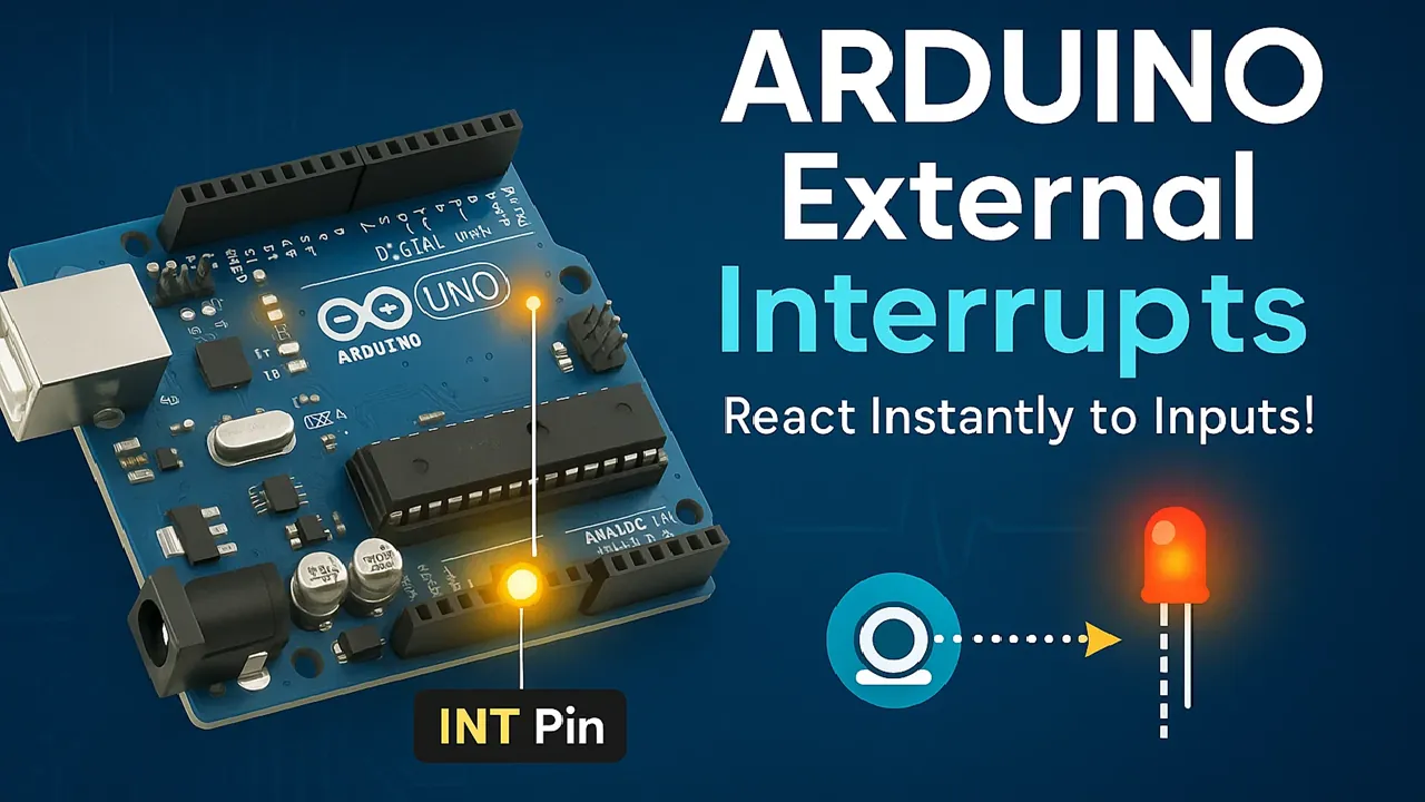
Arduino External Interrupts Guide: How to Use INT0 & INT1 Pins for Responsive Projects
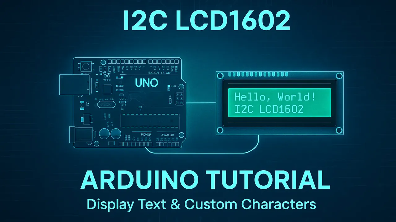
How to Interface I2C LCD1602 Display with Arduino (With Custom Characters)
Arduino W25Q Flash Project Download
Arduino W25Q Flash FAQs
Subscribe
Login
0 Comments
Newest
