
Home ▸ Uncategorized ▸
Updated On: September 14, 2026
CANopen with STM32: Understanding the NMT Protocol
This is Part 4 of the CANopen with STM32 series. In Part 3, we looked at the object dictionary, how it is structured into the communication, device, and application profiles, and how to add a custom object to it using the CANopen Device Designer.
With this tutorial we will start covering the protocols used in CANopen. In this tutorial, we will look at the NMT protocol, the part of CANopen that decides what a node is allowed to do at any given moment. We will go through the four states a node can be in, and understand the NMT command format. We will also see how to control our STM32 node from a computer, where we will start the node, stop it, put it into pre-operational mode, and reset it.
I am using the same STM32H562 project from the earlier parts, and I will continue building on it for the rest of this series.
This is the 4th Part in the STM32 CANopen series. You can check the other tutorials below:
- PART 1: Understanding CANopen protocol
- PART 2: Configuring CAN and Adding I-CUBE-CANOPEN
- PART 3: Understanding the Object Dictionary
CANopen with STM32: Understanding the NMT Protocol — Video Tutorial
This video walks through the CANopen NMT protocol on STM32 — the four node states, the NMT command format, and how start, stop, pre-operational, and reset commands change node behavior. We then build a test application that only runs in the operational state, and verify all the transitions live with TSMaster.
What Is the NMT Protocol
NMT stands for Network Management, and it is the protocol that decides what a CANopen node is allowed to do at any given time. Every node on the bus is always in one of the four states, and that state controls which types of communication are active and which are switched off.
Up until now in this series, our STM32 node has simply been sitting on the bus, responding to whatever SDO requests we sent it. We never really paid attention to what state it was in, because for reading and writing a few objects, it did not matter much. Once we start building an actual application on top of CANopen, this becomes important. An application that spins a motor or drives an output should not just start running the moment the board powers up. It needs a proper trigger, and NMT can be used exactly for this purpose.
In this tutorial, we will send NMT commands from a computer to our STM32 node using TSMaster, and watch the node move between its different states. We will also build a small test application on the STM32 side that only runs while the node is in the operational state, which is a good way to see NMT working in practice rather than just in theory.
The Four CANopen Node States
A CANopen node can be in one of four states, and each one allows a different set of communication types.
- Initialization: This is the start or reset phase of the node. The node initializes the CANopen communication stack and the object dictionary, then it sets up the services it needs, such as NMT, SDO, PDO, and the heartbeat. Once this is complete, the node moves into the pre-operational state automatically, without needing any command from the master.
- Pre-operational: This is where a node is normally configured. SDO communication, PDO configuration, heartbeat timing, and other parameters are all configured here. NMT, SDO, SYNC, and emergency messages all work in this state, but PDO communication does not. To exchange data over PDO, the node has to move to the operational state.
- Operational: This is the normal running state of a node. Every communication type is enabled here, including PDO. This is why an application that depends on PDO data should only run once the node reaches this state.
- Stopped: In this state, only NMT commands and error control messages, such as the heartbeat, are allowed. Nothing else works, not even SDO, which is something we will confirm later in this tutorial.
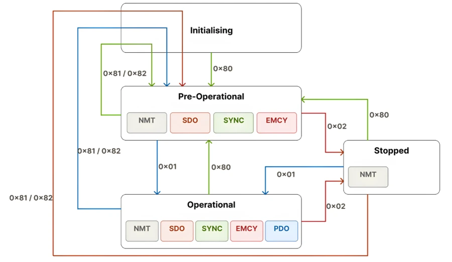
A node is free to move from any of these states to any other, in any order. There is no fixed sequence it has to follow, apart from always starting in Initialization right after power-up or a reset.
NMT Command Format Explained
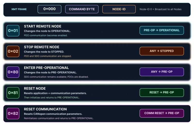
NMT messages always use CAN ID 0x000, and the message itself is only two bytes long.
- Byte 1 – Command specifier: Tells the node what to do.
- Byte 2 – Node ID: Tells the node who the command is meant for. Using node ID 0 here broadcasts the command to every node on the bus, instead of targeting a specific one.
Since our STM32 node’s ID is set to 1, from the earlier parts of this series, any command meant for it will use CAN ID 0x000, with the second byte set to 0x01.
Here are the command specifiers we will be using in this tutorial:
| Command Byte | Action | Resulting State |
|---|---|---|
| 0x01 | Start | Operational |
| 0x02 | Stop | Stopped |
| 0x80 | Enter Pre-operational | Pre-operational |
| 0x81 | Reset Node | Pre-operational (after full reset) |
| 0x82 | Reset Communication | Pre-operational (after partial reset) |
We will look at the difference between the two reset commands separately, later in this tutorial, since it is easy to mix them up.
Running Your Application Only in Operational State
To see NMT working in practice, let’s build a small test application that should run only when the node is in the operational state, and stay off in every other state. For this test, I am simply printing a string on the serial console every 500 milliseconds.
void Application_Process (void)
{
	printf ("Application Running\r\n");
	HAL_Delay(500);
}Since we need the current state of the node, we get it from the NMT callback function, static RET_T nmtInd defined in the app_canopen.c file. This callback fires whenever the master sends an NMT command, and it carries a newState variable telling us the node’s current state.
The different node states are already defined in the co_nmt.h file.
typedef enum {
	CO_NMT_STATE_UNKNOWN = 0,		/**< unknown */
	CO_NMT_STATE_OPERATIONAL = 5,	/**< OPERATIONAL */
	CO_NMT_STATE_STOPPED = 4,		/**< STOPPED */
	CO_NMT_STATE_PREOP = 127,		/**< PRE-OPERATIONAL */
	CO_NMT_STATE_RESET_NODE = 128,	/**< Reset NODE */
	CO_NMT_STATE_RESET_COMM = 129	/**< Reset Communication */
} CO_NMT_STATE_T;We declare a variable in main.c to hold this value:
CO_NMT_STATE_T nmtState;Since the actual state change happens inside app_canopen.c, this variable also needs to be declared as external there, and updated inside the NMT callback function.
extern CO_NMT_STATE_T nmtState;

static RET_T nmtInd(BOOL_T	execute, CO_NMT_STATE_T	newState)
{
	/* USER CODE BEGIN nmtInd */
	printf("nmtInd: New Nmt state %d - execute %d\n", newState, execute);
	nmtState = newState;
	return(RET_OK);
	/* USER CODE END nmtInd */
}Checking the node state alone is not enough. A node can be operational while the CAN bus itself is disconnected, and we do not want the application running in that case either. So we also read the CAN state callback function, which fires whenever the bus state changes.
The different node states are already defined in the co_commtask.h file.
typedef enum {
	CO_CAN_STATE_BUS_OFF,			/**< CAN bus state is bus off */
	CO_CAN_STATE_BUS_ON,			/**< CAN bus state is bus on */
	CO_CAN_STATE_PASSIVE,			/**< CAN bus state is passive */
	CO_CAN_STATE_UNCHANGED			/**< CAN bus state is unchanged */
} CO_CAN_STATE_T;We again declare a variable in main.c to hold this value:
CO_CAN_STATE_T CANState;Next, declare this as an extern variable in app_canopen.c and store the current CAN bus state in the respective callback.
extern CO_CAN_STATE_T CANState;

static void canInd(CO_CAN_STATE_T	canState)
{
	/* USER CODE BEGIN canInd */
	CANState = canState;
	switch (canState)  {
		case CO_CAN_STATE_BUS_OFF:
			printf("CAN: Bus Off\n");
			break;
		case CO_CAN_STATE_BUS_ON:
			printf("CAN: Bus On\n");
			break;
		case CO_CAN_STATE_PASSIVE:
			printf("CAN: Passive\n");
			break;
		default:
			break;
	}
	/* USER CODE END canInd */
}With both variables in place, the application only runs when the node is operational and the bus is connected:
while (1)
{
    MX_CANopen_Process();

    if ((nmtState == CO_NMT_STATE_OPERATIONAL) && (CANState == CO_CAN_STATE_BUS_ON))
    {
        Application_Process();
    }
}If either of these conditions fails, Application_Process never runs.
Why HAL_Delay Breaks CANopen Timing
Our application simply prints the string every 500 milliseconds and the Application_Process function is as follows:
void Application_Process (void)
{
    printf("Application Running\r\n");
    HAL_Delay(500);
}This compiles and runs, but it causes a problem with the heartbeat timing. With the Producer Heartbeat Time set to one second, the heartbeat should be sent once every second. Instead, once this application starts running, the heartbeat stretches out to roughly every four seconds.
The reason is that HAL_Delay blocks the main loop for its entire duration. The CANopen stack still relies on SysTick running in the background, but while HAL_Delay is blocking, the function MX_CANopen_Process() cannot run. This interferes directly with CANopen’s internal timing and heartbeat processing.
To fix this, we need to avoid using blocking delays inside any function that runs alongside the CANopen stack, and use a non-blocking one instead:
void Application_Process (void)
{
    static uint32_t lastTick = 0;

    if ((HAL_GetTick() - lastTick) >= 500)
    {
        lastTick = HAL_GetTick();
        printf("Application Running\r\n");
    }
}The Application_Process function now checks the elapsed time on every loop iteration instead of pausing the loop itself, which lets MX_CANopen_Process() keep running normally. Once the 500 milliseconds has elapsed, the string prints normally.
Testing NMT Commands with TSMaster
Now we will test the actual state transitions using TSMaster on a Windows virtual machine. I have already added a few NMT commands to the Transmit window:
0x80for pre-operational,0x01for operational,0x02for stop,0x81for reset node,0x82for reset communication.
All the commands are addressed to Node 0x01, which is our STM32 Node ID.
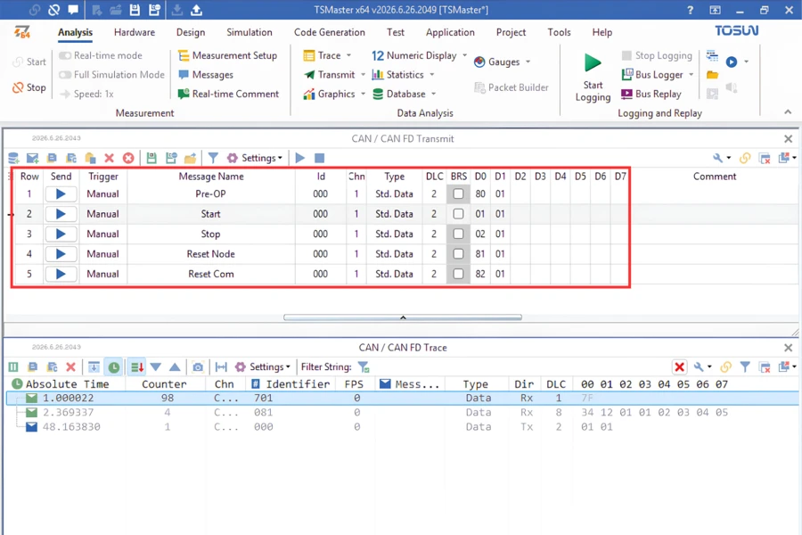
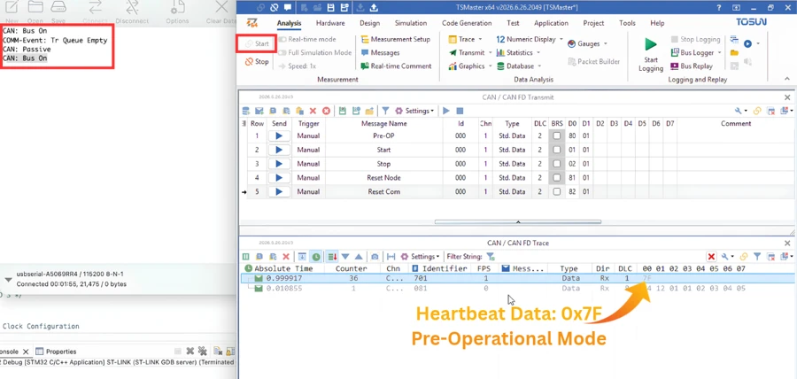
Once Start button on the TSMaster is pressed, the bus moves to the connected state. That satisfies one of our two conditions (CAN Bus ON), but the heartbeat still carries the value 0x7F, which means the node is in pre-operational mode, so the application still does not run.
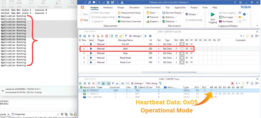
Sending the Start command (0x01) moves the node into the operational state, and the application begins printing on the serial console immediately. The heartbeat value changes to 5, confirming the operational state.
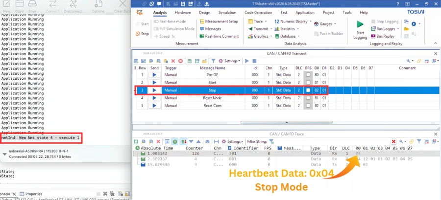
Sending the Stop command (0x02) halts the application right away, and the heartbeat value changes to 04, confirming the stopped state.
Reset Communication vs Reset Node
CANopen provides two different reset commands, and it is worth understanding exactly what each one touches.
Reset Communication (0x82) resets only the communication-related parameters in the object dictionary to their power-on values, and then moves the node directly into the pre-operational state. Application data is left untouched.
Reset Node (0x81) does more. It first performs a Reset Application, where objects in the manufacturer-specific and standard profile areas are reset to their power-on values. After that, it performs a Reset Communication as well, and finally goes through initialization again before settling into pre-operational. Watching the NMT state values during this sequence shows it moving from 128 (Reset Node), to 129 (Reset Communication), and finally to 127 (Pre-operational).
To see the difference between them, I am first writing a value to index 0x2000, subindex 0, using SDO command byte 0x2F:
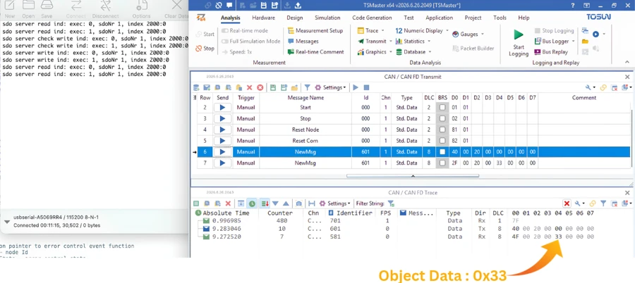
On performing the read operation, the object at index 0x2000:00 returned 0x33 confirming that the write worked.
Now I am going to first test the Reset Communication command. To do this, I am sending the Reset Communication (0x82) and once the reset is complete, I am again reading the object 0x2000:00.
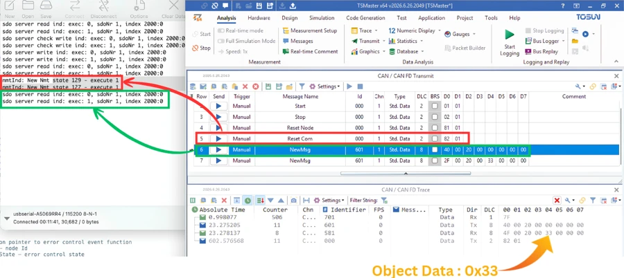
The reset command performs the communication reset (129: CO_NMT_STATE_RESET_COMM) and then put the Node in Pre-Operational Mode (127: CO_NMT_STATE_PREOP). Once the master sends the command to read the object data, the Node returns the data 0x33. This is the same vale that we stored inside the object and this mean that Rest Communication command does not reset the Application or device profiles of the object dictionary.
Now I am going to test the Reset Node command by sending 0x81, and once the reset is complete, I am again reading the object 0x2000:00.
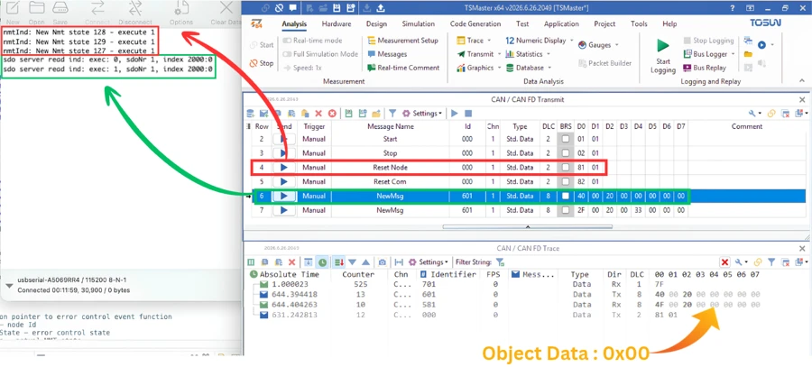
The reset command performs the Node Reset (128: CO_NMT_STATE_RESET_NODE), followed by the communication reset (129: CO_NMT_STATE_RESET_COMM) and then put the Node in Pre-Operational Mode (127: CO_NMT_STATE_PREOP). Once the master sends the command to read the object data, the Node returns the data 0x00. This is the original power-on value of the object, and this confirms that this command resets the object dictionary as well as communication parameters.
So, in short, Reset Communication is the lighter option, useful when communication parameters get stuck or misconfigured. While Reset Node is a complete reset, taking the object dictionary, the communication layer, and the node’s initialization all the way back to their starting point.
CANopen NMT Protocol – Frequently Asked Questions
Does a node have to pass through every state in order?
No. A node can move directly from any state to any other state. There is no fixed order to follow, apart from always starting in Initialization after power-up.
What CAN ID do NMT commands use?
All NMT commands use CAN ID 0x000, regardless of which node they are targeting. The target node is identified by the second data byte instead.
What happens if I send an NMT command with node ID 0?
The command is broadcast to every node connected on the bus, instead of being applied to a single node.
Why did SDO return an abort instead of the expected data during testing?
An abort response still confirms that SDO communication is active in that state. The abort itself just means the specific request was not valid, which is a separate detail from the state check we were testing.
Does disconnecting and reconnecting the CAN bus change the node’s NMT state?
No. The NMT state and the CAN bus state are tracked independently. Reconnecting the bus does not push the node back to pre-operational on its own.
Conclusion
We looked at what the NMT protocol is and how it decides a node’s behavior through four distinct states: Initialization, Pre-operational, Operational, and Stopped. We went through the NMT command format, and used commands 0x01, 0x02, 0x80, 0x81, and 0x82 to move our STM32 node between these states. Along the way, we built a small application that only runs in the operational state with the bus connected, and saw why a blocking delay like HAL_Delay interferes with CANopen’s internal timing.
We also compared Reset Communication and Reset Node directly, confirming with SDO reads that only the latter resets application data back to its power-on values.
In the next part of this series, we will look at SDO communication in detail, covering the different command bytes and the types of data we can exchange between the master and our STM32 node.
Download STM32 CANopen NMT Protocol Project Files
CubeMX project files and HAL source code with the NMT-driven test application, tested on real hardware. Free to download — support the work if it helped you.
Browse More STM32 CANopen Tutorials


Subscribe
Login
0 Comments
Newest

