Home ▸ Arduino ▸ Core Tutorials ▸
Updated On: May 3, 2026
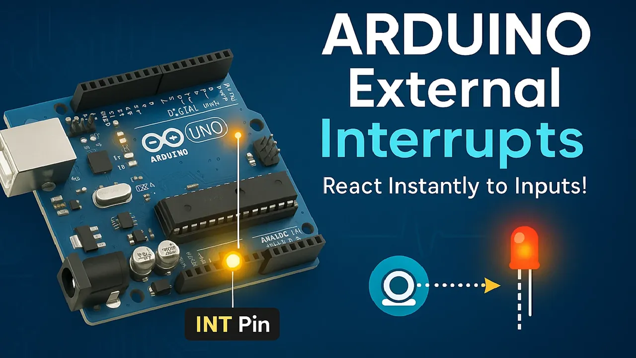
Arduino External Interrupts Tutorial: attachInterrupt(), ISR, Modes & LED Example
When Arduino is running code inside loop(), it cannot react to an external event until the current iteration finishes. For a button press lasting 50 ms, that delay might be imperceptible. For a rotary encoder spinning at speed, a pulse counter, or a motion trigger that fires in microseconds, it is far too slow. External interrupts solve this entirely — they stop the main program instantly, run a dedicated handler function, and return to normal execution without the rest of your code noticing.
In this tutorial you’ll learn exactly what an interrupt is at the hardware level, why it is fundamentally different from polling, which pins on Uno, Nano, Mega, Leonardo, and Zero support hardware interrupts, how to use attachInterrupt() and detachInterrupt() with all four trigger modes (RISING, FALLING, CHANGE, LOW), and how to write a correct, safe Interrupt Service Routine using the volatile flag pattern and millis()-based debounce. A complete working LED toggle project with wiring diagram and code is included. A full project download is at the end.
Before starting, make sure you’re comfortable with the following Arduino Core concepts — they are all used directly in this tutorial:
- Arduino digitalWrite() & digitalRead() — Complete Guide
- Arduino PWM and analogWrite() Explained
- Arduino ADC and analogRead() — Complete Guide
- Arduino UART Serial Communication Tutorial
- Arduino I2C Tutorial with Wire Library
- Arduino delayMicroseconds() — Precision Timing Guide
For interrupt-based multitasking, the Arduino FreeRTOS tutorials build directly on what you’ll learn here. Browse the full Arduino Core tutorials collection for more.
What Are External Interrupts in Arduino?
External interrupts allow your Arduino to instantly respond to external events, such as a button press or a sensor output, without constantly checking their state in the main loop. They make your project more efficient and reactive, especially when timing is critical.
Let’s break down what interrupts are, why they’re useful, and how they’re commonly used in Arduino projects.
Defining “interrupt” in microcontroller terms
In microcontroller systems, an interrupt is a signal that temporarily pauses the main program so the processor can handle a specific task immediately.
When an interrupt occurs, the microcontroller stops executing the main loop, jumps to a special function called an Interrupt Service Routine (ISR), runs that code, and then returns to the main program.
This mechanism ensures that important events, like a sensor trigger or a button press, are handled the moment they occur, without any noticeable delay.
In Arduino, external interrupts are triggered by signals coming from outside the microcontroller, through dedicated hardware pins (like INT0 and INT1).
Interrupt vs Polling — Key Difference
Normally, your Arduino program uses polling, checking the state of input pins repeatedly inside the loop() function. However, polling can miss fast signals if the loop is busy doing other tasks, or if the signal is too brief.
External interrupts solve this problem. Instead of constantly checking, you simply attach an interrupt to a pin, and Arduino will automatically run the ISR whenever the event occurs.
This means your project reacts instantly and doesn’t waste CPU time on unnecessary checks.
Interrupts are especially useful when you need accurate timing or must respond to events that happen unexpectedly.
Common Use Cases for External Interrupts
External interrupts are used in many real-world Arduino applications, especially those that require quick and precise reactions.
Here are some common examples:
- Push buttons and user inputs – detect button presses without delay.
- Rotary encoders – accurately track rotation speed or position.
- Sensors and counters – read pulse signals from sensors like IR detectors or Hall effect sensors.
- Communication signals – handle data-ready or trigger signals from external modules.
By using interrupts, your Arduino becomes more responsive and power-efficient, allowing it to focus on essential tasks instead of running endless checks in the background.
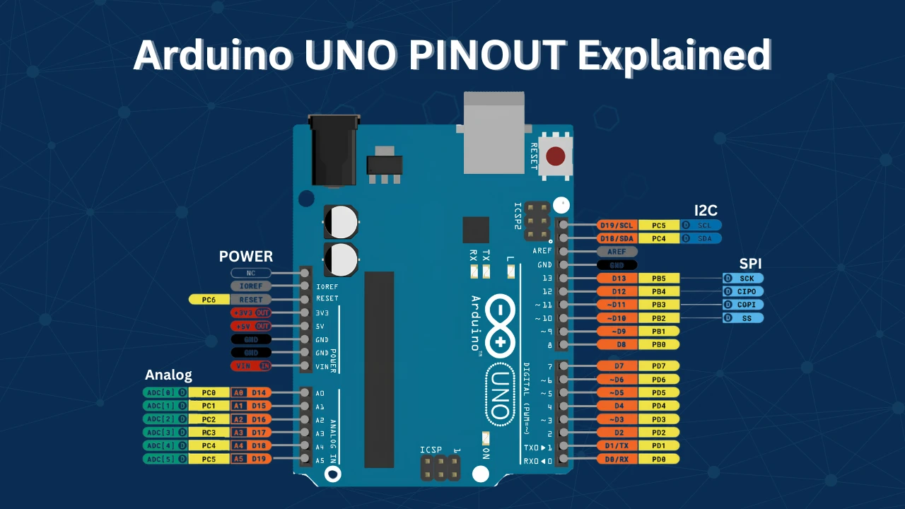
Arduino External Interrupt Pins by Board
Not all Arduino boards have the same interrupt pins, so it’s important to know which pins can be used as external interrupts on your specific board. Most popular Arduino boards, like the Uno or Nano, come with dedicated interrupt pins that can detect changes in voltage and trigger an Interrupt Service Routine (ISR).
Let’s look at the supported pins across different Arduino models and how you can easily identify them for your projects.
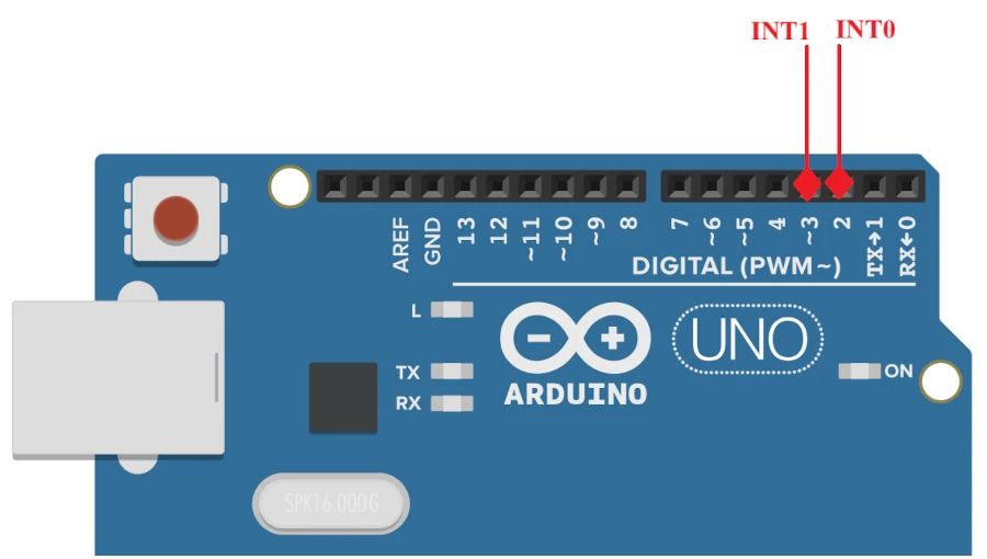
Uno, Nano & Pro Mini — INT0 and INT1 (Pins 2 & 3)
On standard Arduino boards such as the Arduino Uno, Nano, and Pro Mini, there are two external interrupt pins available. These are:
- INT0 → connected to digital pin 2
- INT1 → connected to digital pin 3
You can use these pins with the attachInterrupt() function to trigger actions when a signal changes state.
For example:
attachInterrupt(digitalPinToInterrupt(2), ISR_Function, RISING);Here, the Arduino will execute ISR_Function every time the voltage on pin 2 changes from LOW to HIGH (RISING).
These boards use the ATmega328P microcontroller, which supports exactly two hardware interrupts, one on each of those pins.
Note:
Even though other pins can detect input changes with functions like digitalRead(), only pins 2 and 3 on these boards can handle hardware interrupts for real-time responses.
Expanded boards (Mega, Leonardo, Zero) interrupt pin support
If you’re using larger or more advanced boards like the Arduino Mega, Leonardo, or Zero, you get more interrupt-capable pins.
- Arduino Mega 2560: Supports 6 external interrupts on pins 2, 3, 18, 19, 20, and 21.
- Arduino Leonardo (ATmega32U4): Supports 5 external interrupts on pins 0, 1, 2, 3, and 7.
- Arduino Zero (based on SAMD21): Almost every digital pin can be configured as an interrupt pin.
This flexibility is great for larger projects that need multiple sensors, encoders, or external modules triggering different interrupt routines at once.
Keep in mind that while the function digitalPinToInterrupt(pin) works across most boards, the number of available interrupt pins and their exact mapping may differ depending on the microcontroller.
How to Identify Interrupt Pins with digitalPinToInterrupt()
Finding which pins support external interrupts on your specific Arduino model is quite easy. You can check:
- The official Arduino documentation – Each board’s product page lists its supported interrupt pins.
- The Arduino pinout diagram – Many community-generated diagrams clearly mark interrupt pins with labels like “INT0”, “INT1”, etc.
- Your microcontroller’s datasheet – For advanced users, checking the chip’s datasheet gives detailed information about interrupt vectors and mappings.
If you’re unsure, simply use the function digitalPinToInterrupt(pin) in your code. If it returns a valid interrupt number, the pin supports external interrupts. Otherwise, it doesn’t.
Serial.println(digitalPinToInterrupt(2)); // Returns 0 or 1 if validThis simple test helps confirm whether your chosen pin can be used as an interrupt input, ensuring your project runs reliably on any Arduino board.
Example Code to detect Interrupt Pin
The code below can be used to detect the Hardware Interrupt pin on Arduino board. I am checking for pins 2, 3, 4 and 5.
void setup() {
  Serial.begin(9600);
  delay(2000);  // Wait for Serial Monitor to open

  Serial.println("Checking interrupt numbers:");
  Serial.print("Pin 2: ");
  Serial.println(digitalPinToInterrupt(2));  // Returns 0 for INT0 on Uno
  Serial.print("Pin 3: ");
  Serial.println(digitalPinToInterrupt(3));  // Returns 1 for INT1 on Uno
  Serial.print("Pin 4: ");
  Serial.println(digitalPinToInterrupt(4));  // Returns -1 (no interrupt)
  Serial.print("Pin 5: ");
  Serial.println(digitalPinToInterrupt(5));  // Returns -1 (no interrupt)
}

void loop() {
}The image below shows the result on the Arduino Uno.
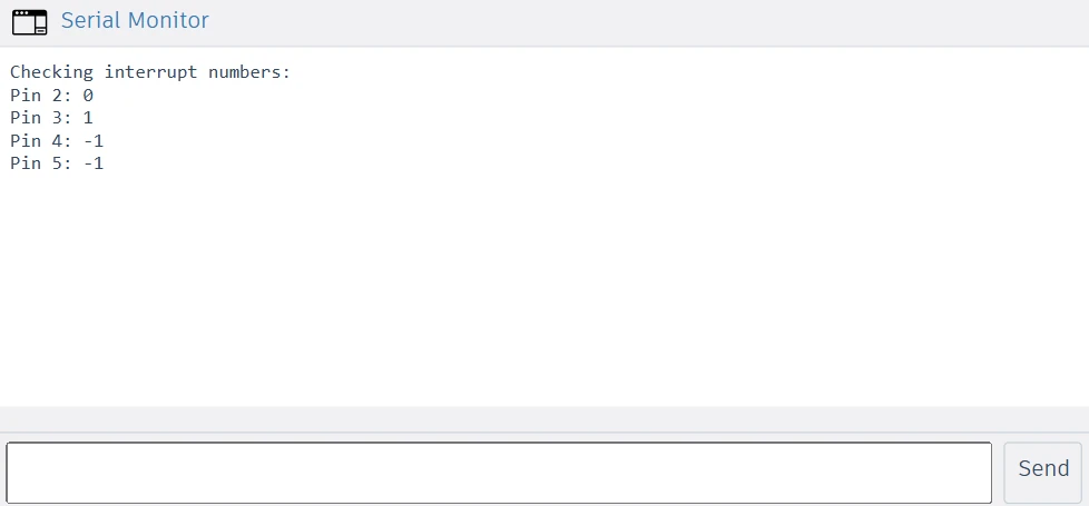
If the function returns a number 0 or higher, it means the pin supports external interrupts. If it returns -1, that pin cannot be used for interrupts on your board.
This means the Pin 2 can be used with INT0, Pin 3 with INT1, whereas the Pins 4 and 5 can not be used as hardware Interrupt pins.
attachInterrupt() & detachInterrupt() — Full Reference
Setting up external interrupts in Arduino is quite simple once you understand the basics. You only need to configure the pin mode, attach the interrupt function, and decide when it should trigger. Arduino provides built-in functions that make this process clean and beginner-friendly.
Let’s go step-by-step through how to configure pins, attach and detach interrupts, and select the correct trigger mode for your project.
Configuring the Pin — INPUT vs INPUT_PULLUP
Before attaching an interrupt, you must configure the pin as an input. This tells the Arduino that the pin will receive a signal from an external device, like a button or sensor.
You can set a pin as:
INPUT— for reading an external signal with your own pull-up or pull-down resistor.INPUT_PULLUP— enables Arduino’s internal pull-up resistor, keeping the pin HIGH by default and detecting a LOW signal when pressed.
Example:
pinMode(2, INPUT_PULLUP); // Configure pin 2 as input with internal pull-upUsing INPUT_PULLUP is convenient because you don’t need an external resistor. The pin stays HIGH when idle and goes LOW when grounded (like pressing a button).
attachInterrupt() Syntax & Parameters
The attachInterrupt() function is the main tool for enabling external interrupts in Arduino. It links a specific pin to a function (called an Interrupt Service Routine or ISR) that runs automatically when the interrupt condition is met.
Syntax:
attachInterrupt(digitalPinToInterrupt(pin), ISR_function, mode);Parameters:
digitalPinToInterrupt(pin)— Converts your Arduino pin number to its corresponding interrupt number.ISR_function— The function to run when the interrupt occurs (must take no parameters and returnvoid).mode— Defines when the interrupt should trigger (RISING, FALLING, CHANGE, or LOW).
Example:
attachInterrupt(digitalPinToInterrupt(2), buttonPressed, FALLING);Here, every time pin 2 goes from HIGH to LOW (button press), Arduino pauses the main program and runs the buttonPressed() function.
Trigger Modes — RISING, FALLING, CHANGE, LOW
The mode parameter in attachInterrupt() decides when the interrupt will trigger. Choosing the right mode ensures reliable and accurate response to your signal.
Here’s what each mode means:
| Mode | Trigger Condition | Example Use Case |
|---|---|---|
| RISING | Signal changes from LOW → HIGH | Detecting pulse start or button release |
| FALLING | Signal changes from HIGH → LOW | Detecting button press |
| CHANGE | Signal changes in either direction | Reading encoder pulses |
| LOW | Signal stays LOW | Continuous low-level detection (less common) |
For most button or sensor triggers, FALLING or RISING is the best choice. Use CHANGE when you need to catch both transitions, such as reading step signals or counting pulses.
Example:
attachInterrupt(digitalPinToInterrupt(3), sensorTrigger, RISING);This line makes Arduino react immediately every time the sensor signal goes HIGH, perfect for time-critical or pulse-counting applications.
detachInterrupt() — Disable an Interrupt
Sometimes, you may want to temporarily disable an interrupt, for example, during a critical section of your program or to avoid false triggers.
To stop an interrupt from responding, use the detachInterrupt() function.
Syntax:
detachInterrupt(digitalPinToInterrupt(pin));Example:
detachInterrupt(digitalPinToInterrupt(2)); // Disable interrupt on pin 2After calling this function, the interrupt will no longer trigger until you re-enable it with attachInterrupt() again. This feature is handy when handling noisy inputs or when you need more control over timing-sensitive tasks.
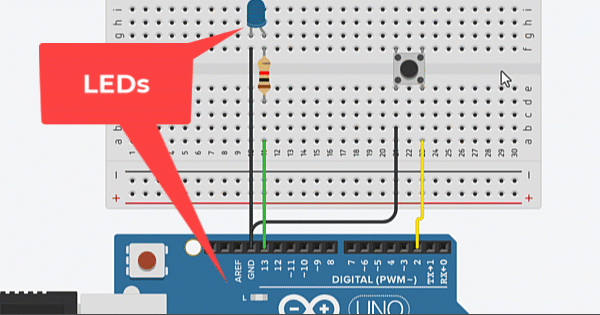
LED Toggle with External Interrupt — Full Example
A simple project helps you learn interrupts fast. In this example a push-button press triggers an external interrupt. The interrupt toggles a LED. The code keeps the ISR short and safe. The main loop applies a small debounce.
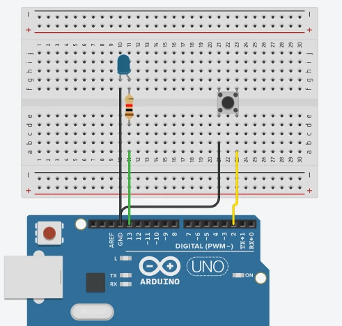
Wiring the Button and LED to INT0 (Pin 2)
Use the Arduino Uno / Nano wiring below:
- Button: one leg → digital pin 2 (INT0). other leg → GND.
- We use
INPUT_PULLUPin code, so the pin stays HIGH until the button connects it to GND (pressed = LOW). - If you prefer, you can use an external pull-up resistor (10 kΩ) between pin 2 and +5V instead of the internal pull-up.
- We use
- LED: anode (long lead) → digital pin 13 (or any digital pin).
- LED cathode (short lead) → GND through a 220 Ω resistor.
Complete Code with ISR Flag Pattern & Debounce
This is a safe, recommended pattern: the ISR only sets a flag. The main loop toggles the LED and applies debounce.
// External interrupt LED toggle - safe ISR pattern

const int buttonPin = 2;   // INT0 on Uno/Nano
const int ledPin = 13;     // built-in LED pin (or any digital pin)

volatile bool irqFlag = false;   // set by ISR, read in loop
unsigned long lastToggle = 0;    // last toggle time for debounce
const unsigned long debounceMs = 50; // debounce window in milliseconds

void setup() {
  pinMode(ledPin, OUTPUT);
  pinMode(buttonPin, INPUT_PULLUP); // use internal pull-up

  // Attach interrupt on pin 2 (INT0). Trigger on FALLING (button press).
  attachInterrupt(digitalPinToInterrupt(buttonPin), handleButtonISR, FALLING);

  Serial.begin(9600);
  Serial.println("Interrupt LED toggle example started");
}

void loop() {
  // If ISR set the flag, handle it here safely.
  if (irqFlag) {
    irqFlag = false;               // clear the flag early

    unsigned long now = millis();
    // Simple debounce: ignore presses too close together
    if (now - lastToggle >= debounceMs) {
      // Toggle LED
      bool current = digitalRead(ledPin);
      digitalWrite(ledPin, !current);
      lastToggle = now;
    }
  }

  // Other non-blocking code can run here
}

// Interrupt Service Routine - keep it short and fast
void handleButtonISR() {
  irqFlag = true;  // mark that button was pressed
}Code Explanation
1. Variable declarations
At the beginning, we define the pins and some helper variables.buttonPin is assigned to pin 2, which supports an external interrupt.ledPin is set to pin 13, which is often the built-in LED on most Arduino boards.
The variable irqFlag is marked volatile because it changes inside the Interrupt Service Routine (ISR) and must remain accessible to both the ISR and the main loop.
We also define a debounceMs variable to prevent multiple triggers from a single press.
2. The setup() function
Inside setup(), we configure the LED as an output and the button as an input with pull-up. This means the button pin will read HIGH when idle and LOW when pressed.
The key function here is:
attachInterrupt(digitalPinToInterrupt(buttonPin), handleButtonISR, FALLING);It tells the Arduino to monitor the falling edge (HIGH → LOW transition) on pin 2. Whenever this happens, the handleButtonISR() function will run immediately, no matter what the main code is doing.
We also start the Serial Monitor for debugging and confirmation messages.
3. The loop() function
The loop() continuously checks if the irqFlag was set by the ISR. When the flag is true, it means the button was pressed, so we clear the flag and handle the toggle action.
We use a small debounce delay by comparing the current time with lastToggle. If enough time has passed since the last toggle, the LED state is flipped using:
digitalWrite(ledPin, !digitalRead(ledPin));This structure keeps the interrupt routine lightweight and moves most logic into the main loop.
4. The Interrupt Service Routine (ISR)
The ISR is the function that runs immediately when the interrupt occurs. Here, our ISR named handleButtonISR() only sets a flag (irqFlag = true;).
We intentionally keep the ISR short and simple, avoiding functions like delay() or Serial.print() that could slow it down. By only setting a flag, we ensure fast execution and reduce the risk of missing other interrupts.
Notes & improvements
- Keep ISRs very short. Set flags or counters in ISR and do heavy work in the main loop.
- If you want immediate action inside the ISR (not recommended for complex tasks), you can toggle the LED inside ISR. But avoid blocking calls and long code there.
- For better hardware reliability, consider an external pull-up or a proper debouncing circuit if the button is very noisy.
Output of the Code
The GIF below shows the simulation for this project on the TinkerCAD simulator.
You can see the external interrupt on the Arduino toggles an LED when a button connected to the interrupt pin is pressed, demonstrating real-time reaction without loop polling.
Practical Tips & Troubleshooting
Working with external interrupts in Arduino is powerful, but it comes with some challenges. If not handled carefully, you might face false triggers, unresponsive programs, or unexpected behavior. Here are a few practical tips and common mistakes to avoid.
Button Bouncing and False Triggers
Mechanical push buttons don’t produce a clean ON/OFF signal — they bounce for a few milliseconds when pressed or released.
This bouncing causes multiple rapid interrupts, which can make your program behave unpredictably (for example, toggling an LED multiple times with one press).
How to fix it:
- Use a software debounce technique by ignoring new interrupts for a short delay (e.g., 50 ms).
- Or, add a hardware debounce using a capacitor or an RC filter.
- Another simple trick is to use a state variable with
millis()to check how much time has passed since the last interrupt.
Interrupt Service Routine (ISR) Best Practices
The Interrupt Service Routine (ISR) is a special function that runs instantly when an interrupt occurs. It must be kept very short and fast.
Here’s what you should remember:
- Avoid using
delay(),Serial.print(), or other time-consuming functions inside the ISR. - If you need to process data later, set a flag variable in the ISR and handle it in the
loop(). - Declare shared variables as
volatileso that the compiler knows they can change at any time.
This keeps your code responsive and prevents interrupt-related bugs.
When Not to Use External Interrupts
External interrupts are useful, but not always necessary. For slower signals like button presses or sensors that update every few seconds, polling inside loop() might be simpler and safer.
Avoid interrupts when:
- Timing precision isn’t critical.
- You already have frequent polling in the main loop.
- You’re running multiple interrupts that may conflict or overload the CPU.
In those cases, a simple digitalRead() check inside the loop is more stable and easier to debug.
Tip: Use interrupts only when you truly need to react instantly — such as counting pulses, detecting motion, or reading high-speed sensor data.
Arduino External Interrupts FAQ
Conclusion
External interrupts are the most fundamental upgrade you can make to how Arduino responds to the physical world. Polling burns CPU cycles checking states that may not have changed. Interrupts let the hardware do that work — the moment the signal changes, the ISR fires, the flag is set, and your main loop handles it in the next cycle without missing anything.
In this tutorial you covered the complete picture: how the ATmega328P hardware interrupt controller works, which pins carry INT0 and INT1 on Uno/Nano versus the expanded sets on Mega and Leonardo, how to configure attachInterrupt() with all four trigger modes, how to write a correct ISR using the volatile flag pattern that keeps the handler to a single line, and how to add millis()-based debounce in the main loop to handle the mechanical noise of a real push button.
From here, interrupts feed naturally into more advanced concurrency. The Arduino FreeRTOS Interrupts tutorial shows how to signal RTOS tasks from an ISR using binary semaphores — the same flag pattern you used here, but with proper task scheduling behind it. The IR Sensor counter and PIR motion detector tutorials both use interrupt-driven pulse counting in practice. Download the full project above and explore the Arduino Core tutorials for the next step.
Download Arduino External Interrupt Project Files
Complete Arduino project with digitalPinToInterrupt() pin checker sketch and full LED toggle example using attachInterrupt() on INT0 (pin 2), volatile flag ISR pattern, and millis()-based debounce. No external libraries required. Compatible with Uno, Nano, Mega, and Leonardo (check board interrupt pin map). Free to download — support the work if it helped you.
Browse More Arduino Core Tutorials
Arduino Nano Pinout – Complete Guide with Diagram
Arduino digitalWrite() and digitalRead(): Complete Guide with Examples
Arduino UART Tutorial: Serial Communication, Send, Receive & LED Control
Arduino ADC and analogRead() Explained: Complete Guide with Examples

Arduino I2C Tutorial: Wire Library, Master/Slave, Scanner & Troubleshooting

Subscribe
Login
0 Comments
Newest
