Updated On: May 10, 2026
TM4C123 Clock Configuration – Main Oscillator, PIOSC, and PLL
Every peripheral on the TM4C123G — timers, UART baud rate generators, PWM modules, ADC sample clocks — derives its frequency from the system clock. Before you can reliably use any of them, you need to consciously configure that clock. Get it wrong and your delays are off, your baud rates misfire, and your timing-sensitive code behaves unpredictably.
This tutorial covers all three clock sources available on the TM4C123G LaunchPad and shows how to configure each using the TivaWare SysCtlClockSet() API in Code Composer Studio (CCS):
- Main Oscillator (MOSC) — the onboard 16 MHz external crystal, highest accuracy
- Precision Internal Oscillator (PIOSC) — 16 MHz on-chip oscillator, no external components needed
- PLL (Phase-Locked Loop) — multiplies the 16 MHz reference up to the maximum 80 MHz system clock
For each configuration you’ll see the SysCtlClockSet() call, the full main function, and how to verify the result using the Watch Expression in the CCS debugger. The complete CubeIDE project is available for download below.
If you haven’t set up your TM4C123G LaunchPad and CCS environment yet, start with the TM4C123G Getting Started tutorial first. For what comes after clock configuration, see Delays with SysCtlDelay and SysTick and the full TM4C123G Tutorial Series.
TM4C123G Clock Sources Overview
The TM4C123G provides three usable clock sources for the system clock. All three are configured through a single TivaWare function: SysCtlClockSet().
| Clock Source | Frequency | External Component | Typical Use |
|---|---|---|---|
| Main Oscillator (MOSC) | 16 MHz | Yes (crystal) | UART, precise timers, production code |
| Precision Internal Oscillator (PIOSC) | 16 MHz | No | Prototyping, cost-sensitive boards |
| PLL (from MOSC) | Up to 80 MHz | Yes (crystal) | Maximum performance applications |
Choose MOSC or PIOSC when 16 MHz is sufficient and you want simplicity. Use PLL when your application needs faster processing or higher-resolution peripheral timing.
What SysCtlClockSet() Does
void SysCtlClockSet(uint32_t ui32Config);The ui32Config parameter is a bitwise OR of TivaWare macros that simultaneously define three things: the clock source, whether the PLL is engaged or bypassed, and the system divider that scales the final output frequency. All three examples in this tutorial use this same function — only the macro combination changes.
Required Includes for Every Configuration
All three configurations in this tutorial use the same set of header files. Add these to the top of your main.c:
#include <stdint.h>
#include <stdbool.h>
#include "inc/hw_memmap.h"
#include "driverlib/debug.h"
#include "driverlib/gpio.h"
#include "driverlib/sysctl.h"What each header provides: <stdint.h> and <stdbool.h> give you uint32_t and bool. hw_memmap.h defines peripheral base addresses. debug.h enables assertion-based error handling. gpio.h exposes GPIO configuration functions. sysctl.h contains SysCtlClockSet(), SysCtlClockGet(), and SysCtlDelay() — the three functions used throughout this tutorial.
Main Oscillator (MOSC) – 16 MHz External Crystal
The Main Oscillator uses the onboard 16 MHz crystal on the TM4C123G LaunchPad as the clock reference. This is the most accurate clock source on the board and is required whenever precision timing is critical — UART baud rate generation, I2C timing, or real-time clock applications.
When configured without PLL, the crystal frequency passes directly to the system clock: 16 MHz in, 16 MHz out.
Clock Configuration Code
void systemClockConfig(void)
{
    SysCtlClockSet(SYSCTL_OSC_MAIN | SYSCTL_USE_OSC | SYSCTL_XTAL_16MHZ);
}Parameter breakdown:
SYSCTL_OSC_MAIN— selects the external crystal (Main Oscillator) as the clock sourceSYSCTL_USE_OSC— uses the oscillator output directly, bypassing the PLLSYSCTL_XTAL_16MHZ— tells TivaWare that the attached crystal is 16 MHz so it can configure the oscillator circuitry correctly
Main Function and Verification
uint32_t sysClock = 0;

int main(void)
{
    systemClockConfig();
    sysClock = SysCtlClockGet();

    while (1) {
        SysCtlDelay(sysClock);
    }
}SysCtlClockGet() reads back the configured system clock frequency in Hz and stores it in sysClock. The SysCtlDelay(sysClock) call in the loop is not functionally meaningful here — it exists only to prevent the compiler from optimizing sysClock out, so you can inspect it in the Watch Expression during debugging. Delays are covered fully in the SysCtlDelay and SysTick tutorial.
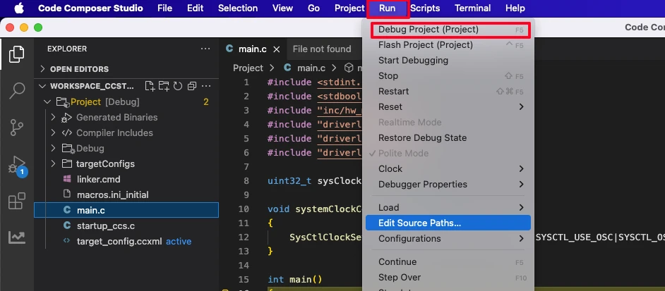
To verify in CCS: Build the project, then click Run → Debug Project.
Once the debugger launches, add sysClock to the Watch Expression panel.
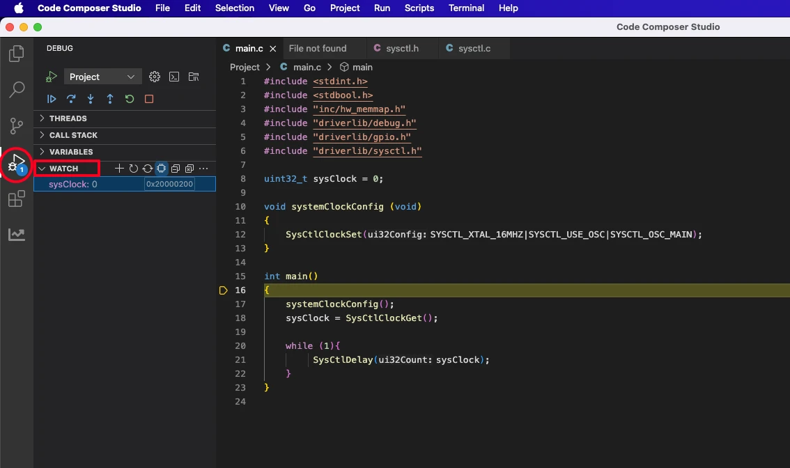
Run the program and observe the value.
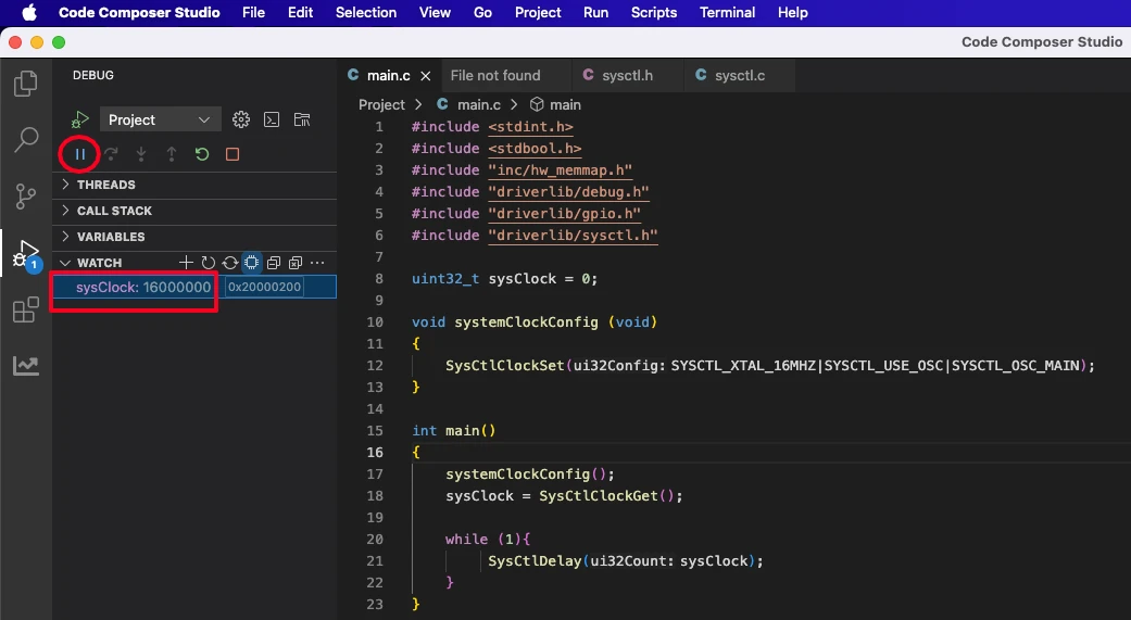
The Watch Expression will display 16000000 (16 MHz), confirming the Main Oscillator is clocking the system directly without PLL multiplication.
Precision Internal Oscillator (PIOSC) – No External Crystal
The Precision Internal Oscillator (PIOSC) is a 16 MHz oscillator built into the TM4C123G die. It requires no external crystal or resonator, which makes it attractive for cost-sensitive board designs and rapid prototyping where you want to test firmware before the final hardware is ready.
The trade-off is accuracy. PIOSC frequency can drift with temperature and supply voltage variations, making it unsuitable for applications that demand tight timing — notably UART at high baud rates and any real-time clock function. For general GPIO toggling, delay loops, or LED control, it works perfectly.
When to Use PIOSC
Use PIOSC when: you are prototyping and don’t yet have a crystal populated, your board design omits the external crystal to reduce component count, or your application doesn’t require precise timing (simple delays, digital I/O, polling loops). Avoid it when: running UART, I2C, or SPI at standard baud rates where frequency accuracy directly determines communication reliability.
Clock Configuration Code
void systemClockConfig(void)
{
SysCtlClockSet(SYSCTL_OSC_INT | SYSCTL_USE_OSC);
}Parameter breakdown:
SYSCTL_OSC_INT— selects the internal oscillator (PIOSC) as the clock source; defaults to 16 MHzSYSCTL_USE_OSC— uses the oscillator output directly, bypassing the PLL; no frequency multiplication occurs
Main Function and Verification
The main function is identical to the MOSC example — only systemClockConfig() changes:
uint32_t sysClock = 0;

int main(void)
{
    systemClockConfig();
    sysClock = SysCtlClockGet();

    while (1) {
        SysCtlDelay(sysClock);
    }
}Build, debug, and add sysClock to the Watch Expression. Run the program.
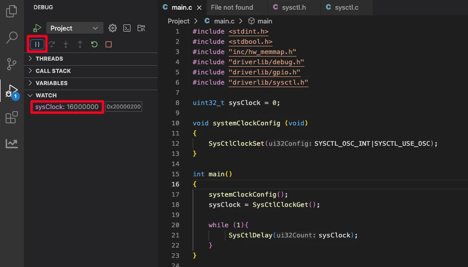
The Watch Expression will again show 16000000. Both MOSC and PIOSC deliver 16 MHz to the system clock when used without PLL. The difference is source accuracy, not frequency — which is why the verified result looks identical.
Using PLL to Reach 80 MHz
Both MOSC and PIOSC provide a 16 MHz system clock. For applications that need faster processing — signal processing, higher-resolution PWM, faster SPI throughput — the Phase-Locked Loop (PLL) inside the TM4C123G can multiply that 16 MHz reference to a much higher system clock, up to the device’s rated maximum of 80 MHz.
How the TM4C123G PLL Works
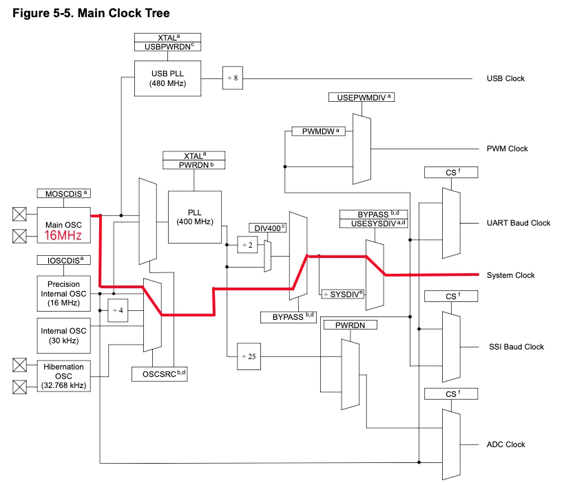
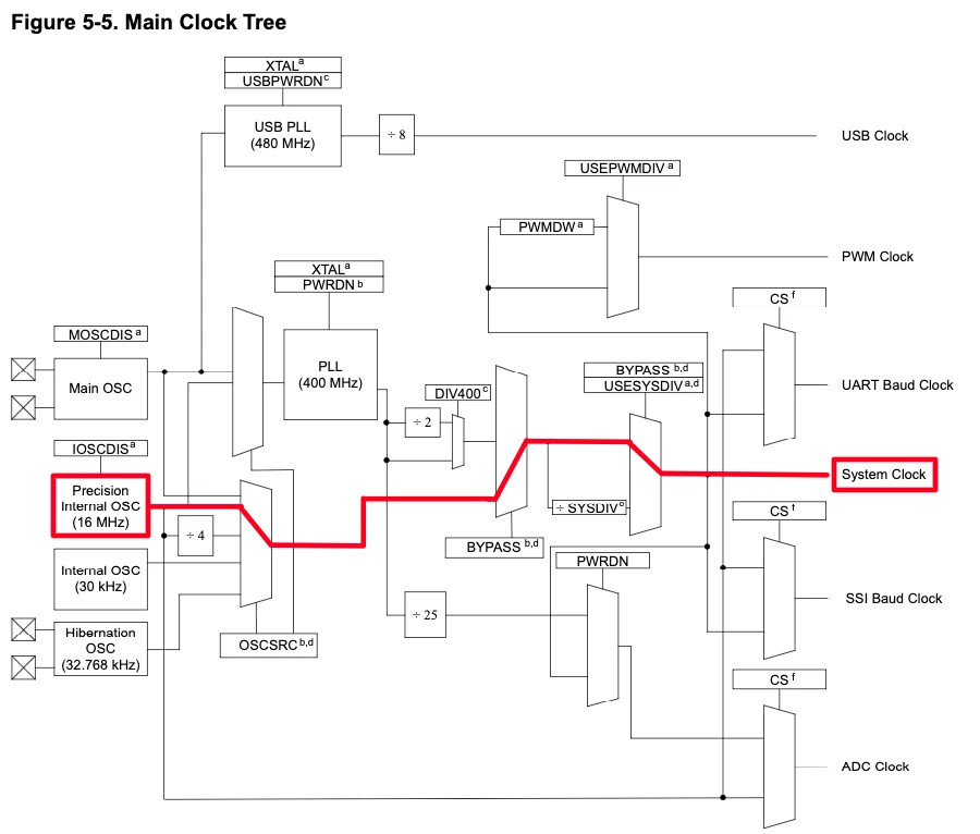
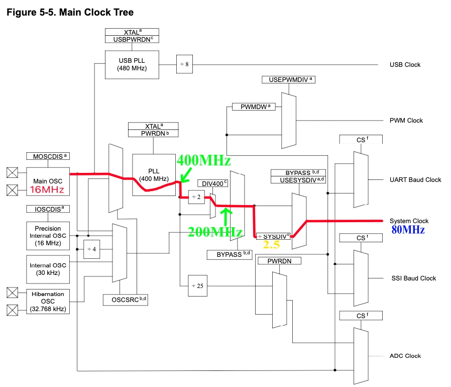
The PLL takes the Main Oscillator as its reference (PIOSC cannot drive the PLL) and multiplies it internally to 400 MHz. That 400 MHz output passes through a fixed divide-by-2 block (the DIV400 stage), producing 200 MHz. A programmable system divider then scales that 200 MHz down to the target system clock frequency.
The math: System Clock = 200 MHz ÷ SYSCTL_SYSDIV. The maximum allowed result is 80 MHz — any divider that would produce more is hardware-capped at 80 MHz automatically.
Clock Configuration Code
void systemClockConfig(void)
{
SysCtlClockSet(SYSCTL_OSC_MAIN | SYSCTL_USE_PLL | SYSCTL_XTAL_16MHZ | SYSCTL_SYSDIV_2_5);
}Parameter breakdown:
SYSCTL_OSC_MAIN— selects the external crystal as the PLL reference inputSYSCTL_USE_PLL— enables the PLL; clock is now multiplied, not passed through directlySYSCTL_XTAL_16MHZ— declares the crystal frequency so TivaWare can configure the PLL input stage correctlySYSCTL_SYSDIV_2_5— divides the 200 MHz post-DIV400 output by 2.5, yielding 80 MHz
System Clock Flow: 16 MHz → 80 MHz
| Stage | Output Frequency |
|---|---|
| External crystal (MOSC) | 16 MHz |
| PLL multiplier | 400 MHz |
| DIV400 fixed divider | 200 MHz |
| SYSCTL_SYSDIV_2_5 | 80 MHz |
| System clock (capped maximum) | 80 MHz |
All core peripherals, the SysTick timer, and the DMA controller run from this 80 MHz clock unless their own prescalers or bus dividers configure them differently.
SYSCTL_SYSDIV Reference Table
Use this table to select other system clock frequencies when 80 MHz is more than your application needs:
SYSCTL_SYSDIV value | Calculation | System Clock |
|---|---|---|
SYSCTL_SYSDIV_2_5 | 200 ÷ 2.5 | 80 MHz (maximum) |
SYSCTL_SYSDIV_3 | 200 ÷ 3 | 66.67 MHz |
SYSCTL_SYSDIV_4 | 200 ÷ 4 | 50 MHz |
SYSCTL_SYSDIV_5 | 200 ÷ 5 | 40 MHz |
SYSCTL_SYSDIV_6 | 200 ÷ 6 | 33.33 MHz |
SYSCTL_SYSDIV_8 | 200 ÷ 8 | 25 MHz |
SYSCTL_SYSDIV_10 | 200 ÷ 10 | 20 MHz |
SYSCTL_SYSDIV_20 | 200 ÷ 20 | 10 MHz |
Lower clock frequencies reduce dynamic power consumption — useful for battery-powered designs where performance headroom can be traded for lower current draw.
Main Function and Verification
uint32_t sysClock = 0;

int main(void)
{
    systemClockConfig();
    sysClock = SysCtlClockGet();

    while (1) {
        SysCtlDelay(sysClock);
    }
}Build, debug, and add sysClock to the Watch Expression as before.
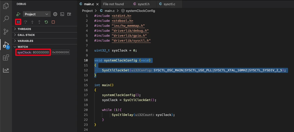
The Watch Expression will show 80000000 — 80 MHz — confirming the PLL is running and the system divider is applied correctly. If you see a lower value, verify that SYSCTL_XTAL_16MHZ matches your actual crystal and that SYSCTL_OSC_MAIN (not SYSCTL_OSC_INT) is selected, since PIOSC cannot feed the PLL.
TM4C123G Clock Configuration FAQs
Conclusion
Clock configuration is the foundation of every TM4C123G project. Whether you choose the Main Oscillator for maximum precision, PIOSC for board simplicity, or PLL for peak 80 MHz performance, the mechanism is the same: a single SysCtlClockSet() call with the right combination of TivaWare macros, followed by a SysCtlClockGet() read to verify what you configured is what you got.
The three configurations shown here cover the full range of what the TM4C123G clock system supports. In practice, most production projects use MOSC + PLL at 80 MHz, falling back to lower divider values only when power consumption is a constraint.
Now that the system clock is configured, the next step is putting it to use. The TM4C123G Delay Tutorial shows how to use SysCtlDelay() and the SysTick timer to generate accurate millisecond and microsecond delays based on the system clock you configured here. After that, explore GPIO digital I/O, UART, and the rest of the TM4C123G Tutorial Series.
Download TM4C123 Clock Configuration Project Files
Complete CCS project with TivaWare source for all three clock configurations — Main Oscillator, PIOSC, and PLL at 80 MHz. Includes systemClockConfig() implementations and main function ready to build and debug. Free to download — support the work if it helped you.
Browse More TM4C123G Tutorials
TM4C123G Delay Tutorial – Using SysCtlDelay and SysTick Timer
TM4C123 GPIO Tutorial – Digital Input and Output using Tiva C LaunchPad
TM4C123 GPIO External Interrupts (Using TivaWare in Code Composer Studio)
TM4C123G UART Tutorial (PART 1) – How to Use UART and Virtual COM Port in Tiva C

TM4C123G UART Tutorial (PART 2): Use Interrupt to Receive Data and Control LEDs

Subscribe
Login
0 Comments
Newest
