
Home ▸ Uncategorized ▸
Published: March 19, 2026
Last Updated: March 19, 2026
Last Updated: March 19, 2026
STM32 FreeRTOS Event Flags : How to Use Event Groups to Synchronize Tasks
In the previous parts of this series, we covered semaphores and mutexes. Semaphores are great for signalling between tasks, while Mutexes protect shared resources. But both of them share one limitation: they can only represent a single condition at a time.
So what happens when you have multiple events firing at the same time, and you want a task to either react to any one of them or wait for all of them before doing something? That is exactly what event flags solve.
In this tutorial, we will look at how event flags work in FreeRTOS and how to use the CMSIS-RTOS V2 API to create and use them. We will also build two practical examples on an STM32 board — one with sensor simulation and another with a real button and UART interrupt.
If you have not gone through the previous parts of this series, I recommend starting from the beginning. The links are as follows:
- CMSIS RTOS Setup and LED blinking
- Creating Multiple Tasks and Priorities in CMSIS RTOS
- How to use Queues for inter task communication
- Using Semaphores in CMSIS RTOS
- Using Mutexes in CMSIS RTOS
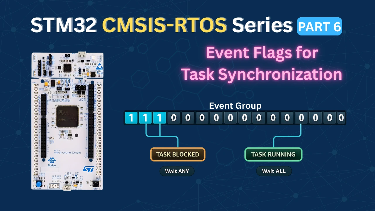
What Are Event Flags in FreeRTOS?
If you have worked with semaphores and mutexes, you already know how to signal between tasks and protect shared resources. But both of them have a fundamental limitation, they represent a single binary condition. Either the semaphore/Mutex is available or it is not.
Event flags solve a different problem. They let you track multiple conditions at the same time using a single object. A task can then choose to wait for any one of those conditions, or wait until all of them are true before proceeding. This kind of flexibility is something you simply cannot achieve with a semaphore alone.
How an Event Group Works Internally
An event group is just a 32-bit integer stored in memory. Each bit in that integer represents a separate event. When an event occurs, the corresponding bit is set to 1. When the event is cleared or consumed, the bit goes back to 0.
bits 31 – 16
bits 15 – 0
An event group holds 32 bits. Each bit is one event.
Event set (1)
Idle (0)
Reserved by FreeRTOS
The key thing to understand is that each bit is completely independent. Setting bit 0 does not affect bit 1 or bit 2. This means multiple events can be active at the same time, and a waiting task can choose exactly which bits it cares about.
How Many Event Flags Can You Use?
The event group is 32 bits wide, but you do not get all 32 bits. FreeRTOS reserves the top 8 bits for its own internal use. That leaves you with 24 bits for your application events.
In practice, 24 independent events in a single event group is more than enough for most embedded applications. And if you ever need more, you can always create a second event group.
The diagram below summarises the bit layout:
| Bits | Usage |
|---|---|
| Bit 0 – Bit 23 | Available for your application events |
| Bit 24 – Bit 31 | Reserved by FreeRTOS — do not use |
Defining Event Flags
Each flag is just a unique bit position. The standard way to define them is with bit shift macros.
#define SENSOR1_BIT   (1 << 0)   // bit 0  →  0x00000001
#define SENSOR2_BIT   (1 << 1)   // bit 1  →  0x00000002
#define SENSOR3_BIT (1 << 2) // bit 2 → 0x00000004When Sensor 1 fires, bit 0 gets set. When Sensor 2 fires, bit 1 gets set. Each sensor owns its own bit, and they never interfere with each other.
You can also combine flags using the OR (|) operator. For example, if you want to check whether either Sensor 1 or Sensor 2 has fired, you write SENSOR1_BIT | SENSOR2_BIT. This gives you a bitmask with both bits set, which you then pass to the wait function.
Click the sensors to fire events
S1
bit 0
bit 0
Sensor 1
S2
bit 1
bit 1
Sensor 2
S3
bit 2
bit 2
Sensor 3
Event group — active bits
0bit 2
0bit 1
0bit 0
↓
Wait mode
Wait for ANY
Task unblocks as soon as at least one flag is set.
Wait for ALL
Task stays blocked until every flag has been set.
Processing Task
Blocked — waiting for events
FreeRTOS Event Flags APIs
FreeRTOS provides a straightforward set of functions for working with event groups. In STM32CubeIDE with CMSIS-RTOS V2, these functions are wrapped under the osEventFlags prefix. We only need three of them for everything we will do in this tutorial.
osEventFlagsNew: Creating an Event Group
Before we can use an event group, we need to create one. The function for this is:
osEventFlagsId_t osEventFlagsNew(const osEventFlagsAttr_t *attr);This allocates memory for the event group from the FreeRTOS heap and returns a handle. We use this handle in every subsequent call to set or wait for flags.
When you add an event group through the CubeMX GUI, this function is called automatically inside the main function. You will see something like this:
myEvent01Handle = osEventFlagsNew(&myEvent01_attributes);You do not need to call this manually. CubeMX generates it for you.
osEventFlagsSet: Setting a Flag
Once the event group exists, any task or ISR can set a flag inside it using:
uint32_t osEventFlagsSet(osEventFlagsId_t ef_id, uint32_t flags);The first parameter is the event group handle. The second is the flag (or combination of flags) you want to set. For example, to set only the Sensor 1 bit, we can use the respective flag:
osEventFlagsSet(myEvent01Handle, SENSOR1_BIT);If you want to set multiple bits at the same time, OR (|) them together:
osEventFlagsSet(myEvent01Handle, SENSOR1_BIT | SENSOR2_BIT);One important thing to note here is, this function is safe to call from both tasks and ISR callbacks. It means you can set an event flag directly inside a button interrupt or a UART receive callback without needing any special ISR-safe variant. We will use this in the practical example later.
The function returns the current value of the event group after the flags are set. You can ignore this return value in most cases.
osEventFlagsWait: Waiting for Flags
This is the most important function in the event flags API. It is where a task blocks and waits for one or more events to occur:
uint32_t osEventFlagsWait(osEventFlagsId_t ef_id,
                           uint32_t flags,
                           uint32_t options,
uint32_t timeout);Let's go through each parameter carefully because the options here are what make event flags so powerful.
- @
ef_id: The handle to our event group. This is what is returned by the functionosEventFlagsNew.
- @
flags: The bit(s) we want to wait for. We can specify one flag or combine multiple with OR:
// Wait for just one flag
osEventFlagsWait(myEvent01Handle, SENSOR1_BIT, ...);

// Wait involving multiple flags
osEventFlagsWait(myEvent01Handle, SENSOR1_BIT | SENSOR2_BIT | SENSOR3_BIT, ...);- @
options: This is where we decide how the function waits. There are two main choices:
osFlagsWaitAny— the task unblocks as soon as at least one of the specified flags is set. If you are waiting for three flags and only one arrives, the task wakes up immediately.osFlagsWaitAll— the task stays blocked until every single specified flag has been set. If you are waiting for three flags, all three must arrive before the task wakes up.
You can also add osFlagsNoClear to either option using OR. By default, the flags are automatically cleared after they are read. If you want to keep them set so other tasks can also read them, add this option:
osFlagsWaitAll | osFlagsNoClear- @
timeout: How long the task should wait before giving up:
0— do not wait at all. If the flags are not already set, return immediately with an error.- Any value in milliseconds — wait for that duration and return an error if the flags do not arrive in time.
osWaitForever— block indefinitely until the flags are set. This is the most common choice in FreeRTOS applications.
- Return value The function returns the value of the event group at the moment the task unblocked. This is very useful when you use
osFlagsWaitAny. You can check the return value to find out which specific flag triggered the wake-up:
uint32_t flags = osEventFlagsWait(myEvent01Handle,
                                   SENSOR1_BIT | SENSOR2_BIT | SENSOR3_BIT,
                                   osFlagsWaitAny,
                                   osWaitForever);

if (flags & SENSOR1_BIT)
{
    // Sensor 1 fired
}
else if (flags & SENSOR2_BIT)
{
    // Sensor 2 fired
}If the function times out or encounters an error, the return value will have one of the error flags set (a value greater than 0x80000000). You can check for this if your application needs error handling.
Here is a quick summary of all the options side by side:
| Option | Behaviour |
|---|---|
osFlagsWaitAny | Unblock when any one flag is set |
osFlagsWaitAll | Unblock only when all flags are set |
osFlagsNoClear | Do not clear flags after reading |
osWaitForever | Block until flags arrive, no timeout |
0 (timeout) | Return immediately if flags not set |
CubeMX Setup for This Project
Here we will create 4 tasks and an Event group. Three Tasks will simulate three sensors by setting respective event flags and the 4th Task read those flags.
Creating the Tasks
Open Middleware → FreeRTOS and go to the Tasks and Queues tab. Here we will create 4 tasks. Task1, Task2, and Task3 will each simulate a sensor by setting an event flag. Task4 is the processing task — it will wait for those flags and decide what to do based on which ones are set.
The image below shows the four tasks configured in CubeMX:
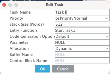


Here are the details of the 4 tasks:
| Task Name | Priority | Stack Size |
|---|---|---|
| Task1 | Normal | 512 words |
| Task2 | Normal | 512 words |
| Task3 | Normal | 512 words |
| Task4 | Normal | 512 words |
All four tasks use the same priority and stack size because they are all doing similar lightweight work.
The stack size of 512 words is enough here because our tasks will use printf to log messages to the serial console. If you are not using printf, you can bring this down to 128 words.
Adding the Event Group
Now go to the Events tab and create a event group that all four tasks will share.
The image below shows the Event tab with one event group added.
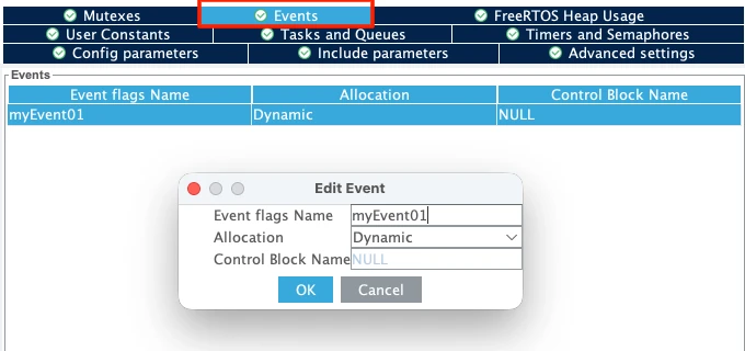
Leave the default name of myEvent01. CubeMX will use this to generate the handle variable myEvent01Handle in the code, which we will use throughout this tutorial.
Make sure the Allocation is set to Dynamic. This means the event group will take its memory from the FreeRTOS heap at runtime rather than being allocated statically at compile time.
Configuring LPUART1 for printf Output
We will use printf to print the received data to a serial console. On the STM32L496 Nucleo board, the Virtual COM port routes UART data through the ST-LINK USB connection. Looking at the board schematic, ST-LINK RX is connected to LPUART1 TX and ST-LINK TX is connected to LPUART1 RX. These map to pins PG7 and PG8.
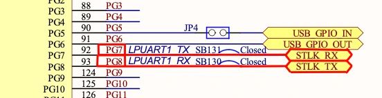
Go to Connectivity and enable LPUART1 in Asynchronous mode. By default, CubeMX assigns pins PC0 and PC1, so change these to PG7 (TX) and PG8 (RX).
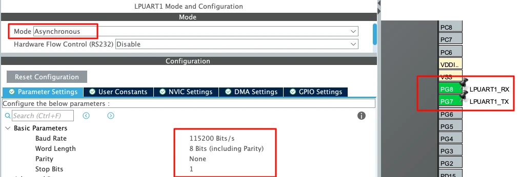
Use the following settings:
| Parameter | Value |
|---|---|
| Baud Rate | 115200 |
| Word Length | 8 bits |
| Parity | None |
| Stop Bits | 1 |
This is the standard UART configuration and matches what we will set in the serial
Waiting for ALL Events
In this first example, we will simulate three sensors using three separate tasks. Each task will set its own event flag and then wait. The processing task will stay blocked until all three flags are set. Only after then will it run and process the data.
Setting the Event Flags from Each Task
The first thing we need to do is define the event bits. Each task gets its own unique bit position.
#define TASK1_EVENT   (1 << 0)
#define TASK2_EVENT   (1 << 1)
#define TASK3_EVENT (1 << 2)Now inside each task, we print a log message to the serial console and then call osEventFlagsSet to set the corresponding bit. Notice that each task has a different delay — Task1 delays 1000ms, Task2 delays 2000ms, and Task3 delays 3000ms. This simulates sensors that report at different rates.
void StartTask1(void *argument)
{
  for(;;)
  {
    printf("Task1 Sending Event\n");
    osEventFlagsSet(myEvent01Handle, TASK1_EVENT);
    osDelay(1000);
  }
}

void StartTask2(void *argument)
{
  for(;;)
  {
    printf("Task2 Sending Event\n");
    osEventFlagsSet(myEvent01Handle, TASK2_EVENT);
    osDelay(2000);
  }
}

void StartTask3(void *argument)
{
  for(;;)
  {
    printf("Task3 Sending Event\n");
    osEventFlagsSet(myEvent01Handle, TASK3_EVENT);
    osDelay(3000);
  }
}Reading All Events in the Processing Task
Inside StartTask4, we call osEventFlagsWait with osFlagsWaitAll. This tells FreeRTOS to keep the task blocked until all three bits are set.
void StartTask4(void *argument)
{
  for(;;)
  {
    printf("Processing Task: Waiting for all sensors...\n");

    osEventFlagsWait(myEvent01Handle,
                     TASK1_EVENT | TASK2_EVENT | TASK3_EVENT,
                     osFlagsWaitAll,
                     osWaitForever);

    printf("Processing Task: All sensors ready! Processing data...\n\n");
    osDelay(500);
  }
}We pass all three bits ORed together as the second parameter. The third parameter osFlagsWaitAll means every one of those bits must be set before the task unblocks. And osWaitForever as the timeout means the task will wait indefinitely.
Output
The image below shows the serial console output after flashing the board. The processing task prints its waiting message first. Then Task1, Task2, and Task3 each send their events. Since Task3 has the longest delay of 3000ms, the processing task has to wait for it before it can proceed. Once all three events arrive, the processing task unblocks, prints the success message, and the whole cycle starts again.

This confirms that osFlagsWaitAll works exactly as expected. No matter how fast or slow each task fires, the processing task stays completely blocked until every single required event has arrived.
Waiting for ANY Event
Now let us switch to a more reactive approach. Instead of waiting for all three events, the processing task will unblock as soon as any one of the three tasks sets its flag. We also want to know exactly which task triggered it so we can handle each event independently.
Switching to osFlagsWaitAny
We only need to make two changes from the previous example. First, we give each task a different and longer delay so they run at clearly separate intervals. Task1 runs every 3000ms, Task2 every 5000ms, and Task3 every 7000ms. This makes it easy to see on the console which task fired and when.
void StartTask1(void *argument)
{
  for(;;)
  {
    printf("Task1 Sending Event\n");
    osEventFlagsSet(myEvent01Handle, TASK1_EVENT);
    osDelay(3000);
  }
}

void StartTask2(void *argument)
{
  for(;;)
  {
    printf("Task2 Sending Event\n");
    osEventFlagsSet(myEvent01Handle, TASK2_EVENT);
    osDelay(5000);
  }
}

void StartTask3(void *argument)
{
  for(;;)
  {
    printf("Task3 Sending Event\n");
    osEventFlagsSet(myEvent01Handle, TASK3_EVENT);
    osDelay(7000);
  }
}Checking Which Flag Was Set
The second change is inside StartTask4. We switch osFlagsWaitAll to osFlagsWaitAny, and we store the return value of osEventFlagsWait into a uint32_t variable called flags. This return value tells us exactly which bit was set when the task unblocked. We then check each bit individually and print the appropriate message.
void StartTask4(void *argument)
{
  uint32_t flags;

  for(;;)
  {
    printf("Processing Task: Waiting for any Event...\n");

    flags = osEventFlagsWait(myEvent01Handle,
                             TASK1_EVENT | TASK2_EVENT | TASK3_EVENT,
                             osFlagsWaitAny,
                             osWaitForever);

    if (flags & TASK1_EVENT) printf("Processing Task: Event received from Task1\n");
    if (flags & TASK2_EVENT) printf("Processing Task: Event received from Task2\n");
    if (flags & TASK3_EVENT) printf("Processing Task: Event received from Task3\n");

    osDelay(500);
  }
}Output
The image below shows the serial console output. Task1 fires first at 3000ms, and the processing task immediately reacts and identifies it as Task1. Then at 5000ms, Task2 fires and the processing task reacts again. At 7000ms, Task3 fires. The processing task does not wait for the others, rather it handles each event the moment it arrives.
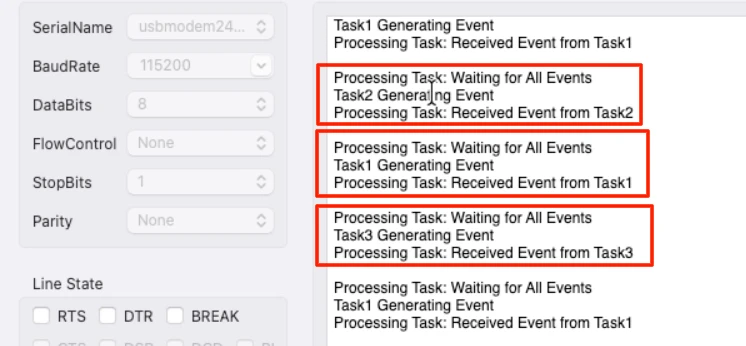
This is the key difference from osFlagsWaitAll. The processing task is now fully reactive. It wakes up for every single event independently rather than waiting for the complete set.
Practical Example: Button and UART Using Event Flags from ISR
So far we have been generating events from tasks. But in real embedded applications, events usually come from hardware interrupts, such as a button press, a UART receive, a timer overflow. In this example we will use both.
The idea is simple. When the button is pressed, an interrupt is triggered and it sets a flag. The button task wakes up and toggles the LED. When data arrives over UART, another interrupt triggers and sets a different flag. The UART task wakes up and prints the received data. Both events are handled independently using a single event group, and the ISR callbacks stay as short as possible — they just set a flag and return immediately.
CubeMX Configuration for Button and UART Interrupt
We need to add two new tasks to the existing project in CubeMX. Go to Middleware → FreeRTOS → Tasks and Queues and add the following:
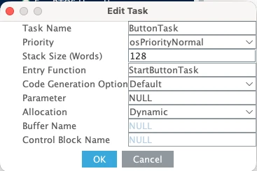
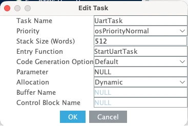
| Task Name | Priority | Stack Size |
|---|---|---|
| ButtonTask | Normal | 128 words |
| UartTask | Normal | 512 words |
ButtonTask uses a smaller stack size of 128 words because it only toggles a GPIO pin and does not use printf. UartTask needs 512 words because it uses printf to send data to the serial console.
Now configure the hardware. Go to the pin configuration and set PA3 as GPIO_EXTI3. This is the pin our button is connected to.
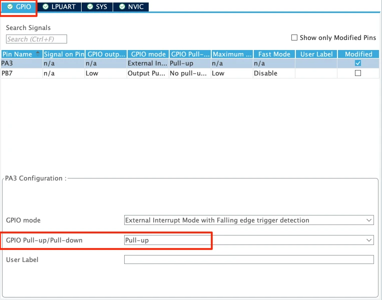
Set the pull to Pull-up so the pin stays high by default and goes low when the button is pressed. Then go to System Core → NVIC and enable the interrupt for the EXTI line 3.
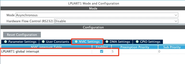
For UART, the low-power UART1 is already enabled for logging. We just need to enable its global interrupt. Go to Connectivity → LPUART1 and under the NVIC Settings tab, enable the LPUART1 global interrupt.
Defining the Flags and the Receive Buffer
At the top of main.c, we define two new event bits and a buffer to hold the incoming UART data. We use bits 3 and 4 so they do not clash with the task event bits we defined earlier.
#define BUTTON_PRESSED   (1 << 3)
#define UART_RECEIVED    (1 << 4)

uint8_t RxData[10];We also need to start UART reception before the FreeRTOS scheduler begins. Add this line in main() just before kernel initialization.
HAL_UART_Receive_IT(&hlpuart1, RxData, 5);This tells the HAL library to receive 5 bytes in interrupt mode and fire the RX complete callback when done.
Setting Flags Inside the ISR Callbacks
When the button is pressed, the GPIO EXTI callback is called. We simply call osEventFlagsSet to set the BUTTON_PRESSED flag:
void HAL_GPIO_EXTI_Callback(uint16_t GPIO_Pin)
{
  osEventFlagsSet(myEvent01Handle, BUTTON_PRESSED);
}When 5 bytes are received over UART, the RX complete callback fires. Here we set the UART_RECEIVED flag and immediately re-arm the interrupt. The HAL library automatically disables the UART receive interrupt after every single callback. If we do not call HAL_UART_Receive_IT again here, the interrupt will only fire once and then stop working completely.
void HAL_UART_RxCpltCallback(UART_HandleTypeDef *huart)
{
osEventFlagsSet(myEvent01Handle, UART_RECEIVED);
HAL_UART_Receive_IT(&hlpuart1, RxData, 5);
}Notice how short both callbacks are. There is no processing, no printf, no heavy logic — just a single flag set and we are out. This is exactly how ISRs should be written in an RTOS application.
Button Task and UART Task Implementation
The button task waits for the BUTTON_PRESSED flag. Since we are only waiting for one flag here, it does not matter whether we use osFlagsWaitAny or osFlagsWaitAll — both behave the same way when there is only one bit involved. Once the flag arrives, we toggle pin PB7 where the LED is connected. The 500ms delay at the end also helps debounce the button.
void StartButtonTask(void *argument)
{
for(;;)
{
osEventFlagsWait(myEvent01Handle, BUTTON_PRESSED, osFlagsWaitAll, osWaitForever);
HAL_GPIO_TogglePin(GPIOB, GPIO_PIN_7);
osDelay(500);
}
}The UART task waits for the UART_RECEIVED flag. Once it arrives, we print the received data to the serial console.
void StartUartTask(void *argument)
{
for(;;)
{
osEventFlagsWait(myEvent01Handle, UART_RECEIVED, osFlagsWaitAll, osWaitForever);
printf("Data Received: %s\n", RxData);
}
}Here is the complete code for this section:
/* USER CODE BEGIN PD */
#define BUTTON_PRESSED (1 << 3)
#define UART_RECEIVED (1 << 4)
/* USER CODE END PD */
/* USER CODE BEGIN PV */
uint8_t RxData[10];
/* USER CODE END PV */
/* Add this in main() before osKernelStart() */
HAL_UART_Receive_IT(&hlpuart1, RxData, 5);
void HAL_GPIO_EXTI_Callback(uint16_t GPIO_Pin)
{
  osEventFlagsSet(myEvent01Handle, BUTTON_PRESSED);
}
void HAL_UART_RxCpltCallback(UART_HandleTypeDef *huart)
{
  osEventFlagsSet(myEvent01Handle, UART_RECEIVED);
  HAL_UART_Receive_IT(&hlpuart1, RxData, 5);
}
void StartButtonTask(void *argument)
{
  for(;;)
  {
    osEventFlagsWait(myEvent01Handle, BUTTON_PRESSED, osFlagsWaitAll, osWaitForever);
    HAL_GPIO_TogglePin(GPIOB, GPIO_PIN_7);
    osDelay(500);
  }
}
void StartUartTask(void *argument)
{
  for(;;)
  {
    osEventFlagsWait(myEvent01Handle, UART_RECEIVED, osFlagsWaitAll, osWaitForever);
    printf("Data Received: %s\n", RxData);
  }
}Output
The GIF below shows both events working independently. Every time the button is pressed, the LED toggles. Every time 5 bytes are sent from the computer over UART, the data appears on the serial console. Neither task interferes with the other, and the system responds immediately to each event.

This is the right way to handle hardware events in a FreeRTOS application. Keep the ISR lean, set a flag, and let the task handle the actual work. The event group ties everything together cleanly without needing a separate semaphore for each interrupt source.
Video Tutorial
STM32 FreeRTOS Event Flags — Event Groups Tutorial Video
Watch me configure the event group in CubeMX, define the event bits, write the task functions using osEventFlagsSet() and osEventFlagsWait(), demonstrate waiting for ALL and ANY events, and verify the output on the serial console.
Watch the FreeRTOS Event Flags TutorialConclusion
In this tutorial, we covered event flags in FreeRTOS and how to use them to synchronize multiple tasks using a single event group. We started with the basics — how an event group works internally as a 32-bit value, how to define event bits, and how to use osEventFlagsSet and osEventFlagsWait to set and wait for flags. We then built two practical examples — one where the processing task waits for all three sensor events before running, and another where it reacts to any single event as soon as it arrives.
Event flags are a powerful tool in any RTOS application. They give you flexibility that semaphores and mutexes simply cannot match — you can track multiple conditions at once, choose whether to wait for any one of them or all of them, and even use them directly from ISR callbacks to keep your interrupt handlers lean and fast. Once you start using event flags, you will find yourself reaching for them in almost every project that involves multiple sources of events.
In the next part of this series, we will look at software timers in FreeRTOS. Software timers let you execute a function after a set period of time without blocking a task or wasting CPU cycles in a delay loop. They are extremely useful for periodic tasks, timeout handling, and debouncing — and they integrate cleanly with everything we have built so far. Stay tuned.
Browse More STM32 Tutorials
LVGL on STM32 || PART 1
Modbus #2. STM32 Master Reads Coils and inputs

STM32 as I2C SLAVE || PART 7

STM32 Ethernet PART 11 – HTTP Server using AJAX PART1
Interface I2C LCD1602 (PCF8574) with STM32 | HAL Tutorial

Interface LED Dot Matrix with STM32 via SPI | PART1
STM32 UART using LL Drivers (Part 5): Receive Using DMA (Normal and Circular Mode)
STM32 RTOS Project Download
STM32 FreeRTOS Events FAQs
Subscribe
Login
0 Comments
Newest
