Home ▸ STM32 Tutorials ▸
Published: August 11, 2021
Last Updated: March 5, 2026
Last Updated: March 5, 2026
How to Configure a UDP Client on STM32 Using lwIP Raw API
This is Part 3 of the STM32 Ethernet tutorial series. In this tutorial, we will set up a UDP Client on STM32 using the lwIP Raw API. If you have already gone through Part 2, you know how a UDP Server works on STM32. Now we flip the roles, the STM32 acts as the client, and it connects to an external server.
The hardware setup I used here is the same as in Part 1 of this series. I covered the hardware connection and lwIP configuration there, so make sure you check that out first if you haven’t already.
What is a UDP Client and Why Use It on STM32?
Before we dive into the code, let me quickly explain what a UDP Client is and why we are using it here.
What is UDP?
UDP stands for User Datagram Protocol. It is one of the core communication protocols used in networking. We use it to send data from one device to another over a network.
The key thing about UDP is that it is connectionless. This means the sender does not wait for the receiver to confirm that the data arrived. It just sends the data and moves on.
Compare this to TCP, where both devices go through a handshake before sending anything. TCP makes sure every packet arrives safely. UDP does not do that.
There is no “connection” being maintained. Every packet is independent. The server does not know whether the client is still online, and it does not care. This is what makes UDP so lightweight.
On STM32, we use the lwIP Raw API to implement this. The Raw API is callback-based. We register a function, and lwIP calls it automatically every time a UDP packet arrives. We do not have to poll or block.
What is a UDP Client?
In a typical network setup, we have two sides, a client and a server. The server sits and waits. It listens on a specific port for incoming data. The client is the one that starts the conversation. It connects to the server’s IP address and port, sends data, and optionally waits for a response.
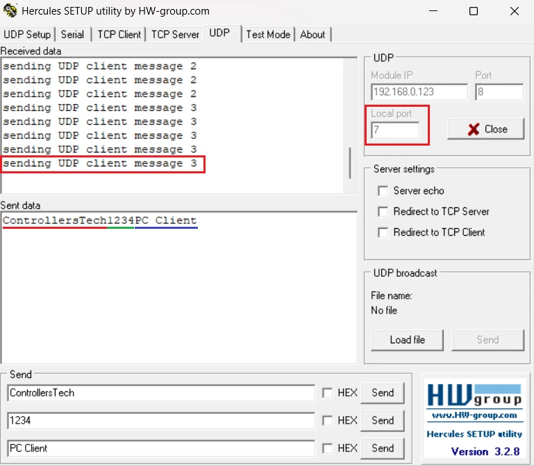
So when we say STM32 is acting as a UDP Client, it means the STM32 is the one initiating the communication. It is reaching out to an external server, in our case, a PC running a tool like Hercules.
How is UDP Different from TCP?
TCP is like sending a registered letter. You know it will reach the destination. You get a confirmation. If it gets lost, it is resent automatically.
UDP is like dropping a flyer in a mailbox. You send it and forget it. You do not know if someone picked it up or not. But it is much quicker and simpler.
Here is a quick comparison to keep in mind:
| Feature | UDP | TCP |
|---|---|---|
| Connection | Connectionless | Connection-based |
| Speed | Faster | Slower |
| Reliability | No guarantee | Guaranteed delivery |
| Overhead | Low | Higher |
| Use Case | Real-time data, streaming | File transfer, web browsing |
When Should You Use a UDP Client vs a UDP Server?
This depends on who starts the communication.
- We should use a UDP Server when we want the STM32 to sit and wait for commands or data from a PC or another device. The external device initiates contact.
- We should use a UDP Client when we want the STM32 to actively reach out and send data. For example, sending temperature readings to a data collection server every second. The STM32 initiates contact.
In this tutorial, our STM32 will act as the client. It will connect to a server running on a PC, send a message every second, and also receive any response the server sends back.
STM32 CubeMX Configuration
The Ethernet configuration will remain the same as we covered in the previous tutorial. Although we will configure the timer here, so the client can send messages to the server periodically.
The image below shows the clock configuration for this project.
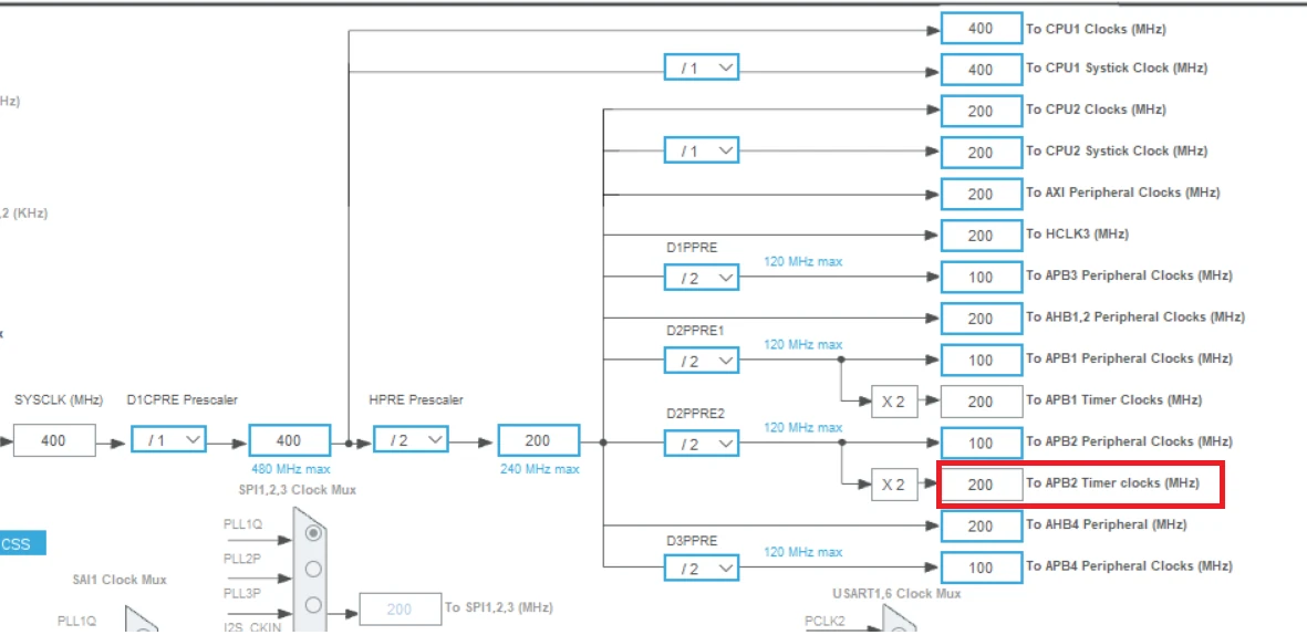
You can see the APB2 Timer clock is running at 200MHz. We will use Timer 1, which is connected to APB2 bus, hence the TIM2 clock is also at 200MHz.
Timer Configuration
The image below shows the TIM1 configuration for periodic interrupt.
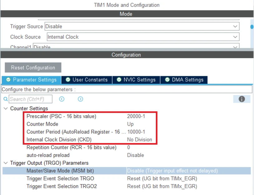
As I mentioned earlier, the TIM1 is connected to APB2 Bus, hence it is running at 200MHz. We will use the prescaler and ARR combination to bring this clock down to 1Hz.
Understanding the STM32 UDP Client Code
Now let’s get into the actual code. I have broken the entire implementation into three steps. Each step handles one specific part of the communication — connecting, receiving, and sending. Let’s go through each one carefully.
Before we look at the individual functions, here is a quick overview of what we are doing. The STM32 will create a UDP control block, bind it to its own IP, connect to the server, and then start exchanging data. A timer handles the periodic sending, and a callback handles the incoming data.
Step 1 – Connect the UDP Client to the Server
The first thing we need to do is set up the connection. I created a function called udpClient_connect() for this. This function does all the setup work — creating the control block, binding to the local IP, connecting to the server, and registering the receive callback.
Here is the full function:
void udpClient_connect(void)
{
    err_t err;

    /* 1. Create a new UDP control block  */
    upcb = udp_new();

    /* Bind the block to module's IP and port */
    ip_addr_t myIPaddr;
    IP_ADDR4(&myIPaddr, 192, 168, 0, 123);
    udp_bind(upcb, &myIPaddr, 8);

    /* configure destination IP address and port */
    ip_addr_t DestIPaddr;
    IP_ADDR4(&DestIPaddr, 192, 168, 0, 100);
    err = udp_connect(upcb, &DestIPaddr, 7);

    if (err == ERR_OK)
    {
        /* 2. Send message to server */
        udpClient_send();

        /* 3. Set a receive callback for the upcb */
        udp_recv(upcb, udp_receive_callback, NULL);
    }
}Below is the explanation of the code:
Creating the UDP Control Block
upcb = udp_new();The very first thing we do is create a UDP Protocol Control Block (PCB). Think of this as the core data structure that lwIP uses to manage our UDP connection. It stores everything — local IP, remote IP, ports, callbacks, and more.
We call udp_new() to create this block. It returns a pointer, which we store in upcb. We will use this pointer in every other UDP function we call.
If udp_new() returns NULL, it means lwIP could not allocate memory for the control block. In a real production project, we should always check for this. But for this tutorial, we keep things simple.
Binding to the Local IP and Port
ip_addr_t myIPaddr;
IP_ADDR4(&myIPaddr, 192, 168, 0, 123);
udp_bind(upcb, &myIPaddr, 8);Next, we bind the control block to the STM32’s own IP address and local port.
First create an ip_addr_t variable called myIPaddr. Then use the IP_ADDR4() macro to set it to 192.168.0.123. This is the static IP address I have assigned to the STM32 in this project.
Then call udp_bind() with three arguments: the control block, the IP address, and the local port number. Here I am using port 8 as the local port. Any incoming data addressed to 192.168.0.123:8 will be routed to this control block.
Note:
The IP address and port you use here must match what you have configured in CubeMX and your lwIP settings. If these do not match, the communication will not work.
Connecting to the Server
ip_addr_t DestIPaddr;
IP_ADDR4(&DestIPaddr, 192, 168, 0, 100);
err = udp_connect(upcb, &DestIPaddr, 7);Now we set the destination, the server we want to talk to.
We create another ip_addr_t variable, this time called DestIPaddr, and set it to 192.168.0.100. This is the IP address of my PC, which will be running the Hercules UDP tool as the server.
Then call udp_connect() with the control block, the server IP, and the server port 7. The function returns an error code, which we store in err. We check this before doing anything else.
Sending the First Message and Registering the Callback
if (err == ERR_OK)
{
    udpClient_send();
    udp_recv(upcb, udp_receive_callback, NULL);
}If the connection setup was successful, we do two things.
First, we call udpClient_send() to send the very first message to the server right away. This lets the server know the client is online and ready.
Second, we call udp_recv() to register the receive callback function. From this point on, any data the server sends back to us will automatically trigger that function.
Step 2 – Handle the Receive Callback
Every time the server sends data back to our STM32 client, lwIP automatically calls the receive callback. I named this function udp_receive_callback(). Here is the code:
void udp_receive_callback(void *arg, struct udp_pcb *upcb, struct pbuf *p,
                           const ip_addr_t *addr, u16_t port)
{
    /* Copy the data from the pbuf */
    strncpy(buffer, (char *)p->payload, p->len);

    /* increment message count */
    counter++;

    /* Free receive pbuf */
    pbuf_free(p);
}Inside this function, we copy the data from payload into our local buffer. This counter is used in the send function to number each outgoing message.
After we are done with the received data, we must free the packet buffer using pbuf_free(). lwIP manages a pool of packet buffers internally. If we do not release them after use, the pool will run out very quickly.
Step 3 – Send Data to the Server Using a Timer
Now let’s look at how we send data. I wanted the STM32 to send a message every 1 second automatically, without any manual trigger. To do this, I used a hardware timer with a 1-second period.
Here is the full code for both the timer callback and the send function:
void HAL_TIM_PeriodElapsedCallback(TIM_HandleTypeDef *htim)
{
    udpClient_send();
}

static void udpClient_send(void)
{
    struct pbuf *txBuf;
    char data[100];

    int len = sprintf(data, "sending UDP client message %d", counter);

    /* allocate pbuf from pool */
    txBuf = pbuf_alloc(PBUF_TRANSPORT, len, PBUF_RAM);

    if (txBuf != NULL)
    {
        /* copy data to pbuf */
        pbuf_take(txBuf, data, len);

        /* send udp data */
        udp_send(upcb, txBuf);

        /* free pbuf */
        pbuf_free(txBuf);
    }
}The code is explained below:
Using a Timer to Trigger Periodic Sending
void HAL_TIM_PeriodElapsedCallback(TIM_HandleTypeDef *htim)
{
    udpClient_send();
}I configured a hardware timer in CubeMX with a period of 1 second. Every time the timer overflows, HAL calls HAL_TIM_PeriodElapsedCallback() automatically.
Inside this callback, I simply call udpClient_send(). This means the STM32 will send a new UDP packet to the server every single second, completely on its own, without any polling or delay in the main loop.
Preparing the Message
char data[100];
int len = sprintf(data, "sending UDP client message %d\r\n", counter);Inside udpClient_send(), we first prepare the message string. I use sprintf() to format the message and store it in a local data array.
The message looks like this: "sending UDP client message 3" — where 3 is the current counter value. Every time the server responds, the counter increments. So each message we send shows how many server responses we have received so far.
sprintf() also returns the length of the string it wrote, which I store in len. We need this length when allocating the packet buffer.
Allocating the Transmit Packet Buffer
txBuf = pbuf_alloc(PBUF_TRANSPORT, len, PBUF_RAM);Before we can send anything, we need to allocate a packet buffer to hold our data. I call pbuf_alloc() with three arguments.
PBUF_TRANSPORTtells lwIP that this buffer is for transport layer use.lenis the size of our data in bytes.PBUF_RAMtells lwIP to allocate this buffer from RAM.
After calling this, txBuf either points to a valid buffer, or it is NULL if memory was unavailable. That’s why we check if (txBuf != NULL) before doing anything else.
Copying Data into the Buffer and Sending
pbuf_take(txBuf, data, len);
udp_send(upcb, txBuf);
pbuf_free(txBuf);Once we have a valid buffer, use pbuf_take() to copy the message into the packet buffer. It takes three arguments: the destination pbuf, the source data pointer, and the number of bytes to copy. After this call, our message is safely inside txBuf and ready to go out on the wire.
Then we call udp_send() with our control block and the transmit buffer. This is the line that actually sends the UDP packet to the server.
Just like with the receive buffer, we must free the transmit buffer after sending. Even though the data has already been sent, the memory lwIP used to hold it is still allocated until we explicitly release it.
Testing the STM32 UDP Client
The image below shows the data sent by the STM32 client is received by the UDP server (Hercules). You can see the message count is increased to 3 because the server sent 3 messages to the client.
Video Tutorial
STM32 UDP Client Video Tutorial
This STM32 UDP Client tutorial shows you the complete code and testing process in action. I walk you through the udpClient_connect function, the receive callback, and the periodic send function step by step. Watch the video and follow the written guide together to easily set up a UDP Client and test it with your PC acting as the server.
Watch the UDP Client TutorialConclusion
In this tutorial we covered how to set up an STM32 as a UDP Client using the lwIP Raw API. We created a UDP control block, bound it to the STM32’s local IP, connected it to the server, and registered a receive callback. On top of that, we used a 1-second hardware timer to automatically send a new packet to the server every second — giving us clean, two-way UDP communication between the STM32 and a PC.
One thing to always keep in mind — free the packet buffer after every send and receive. Skipping this will drain the lwIP memory pool fast and silently break your communication. Also make sure the IP addresses and ports in your code match what you have set in CubeMX and on your PC.
In the next part of this series, we move on to TCP Server configuration on STM32. TCP adds reliability on top of what we did here, so it is a natural next step. Check it out when you are ready.
Check out more STM32 Ethernet Tutorials
STM32 Ethernet Tutorial (PART 4): TCP Server with lwIP Raw API
STM32 Ethernet PART 5 – How to Configure TCP Client
STM32 Ethernet PART 6 – How to Configure Simple HTTP Webserver
STM32 Ethernet PART 6.1 – Configure HTTP Webserver using SSI

STM32 Ethernet PART 6.2 – Configure HTTP Webserver using CGI
STM32 Ethernet PART 7 – UDP Server using LWIP NETCONN (RTOS)


Hi, thank you for this demo. It works for me fine except the receive callback is not called by the program. It sends udp data to the server once per second, but when I send some data from the server, it even does not go into the callback function. I am using hercules and I disabled all other LAN adapters and firewall. Any idea where could be the problem?
Thank you.