Home ▸ STM32 Tutorials ▸
Published: October 17, 2025
Last Updated: February 6, 2026
Last Updated: February 6, 2026
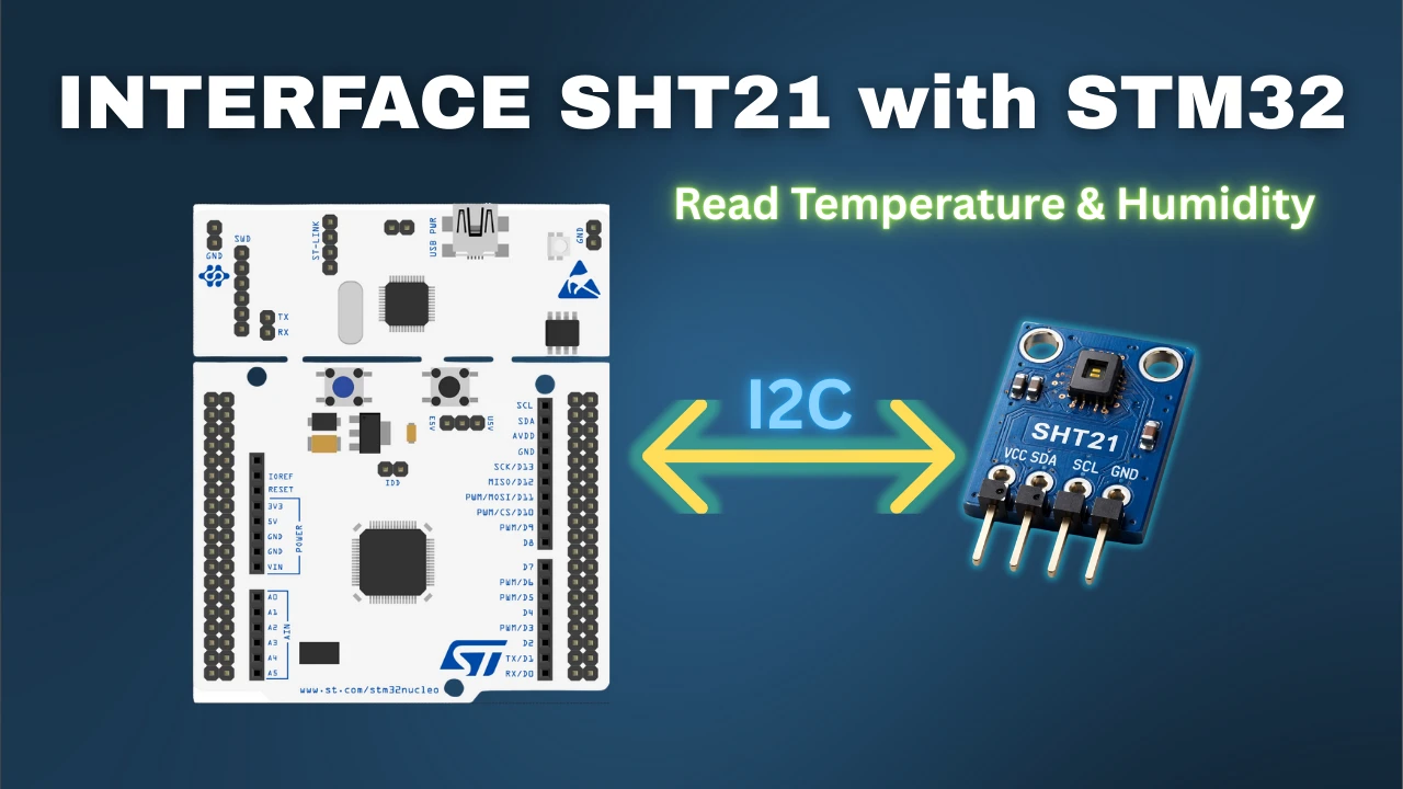
Interface SHT21 Temperature and Humidity Sensor with STM32 using I2C
The SHT21 sensor is a compact and reliable temperature and humidity sensor developed by Sensirion. It provides fully calibrated digital output and communicates using the I²C protocol, which makes it very easy to connect with microcontrollers like STM32.
In this tutorial, you’ll learn how to interface the SHT21 sensor with STM32 using I2C. We’ll use the STM32F103C8 (Blue Pill) board to read temperature and humidity values from the sensor. You’ll see how to configure the I2C peripheral in STM32CubeMX, add the SHT21 library, and display the sensor readings on the serial console using UART.
The SHT21 is one of the simplest sensors to interface, it needs only a few commands and delivers highly accurate data. By the end of this guide, you’ll have a fully working project that reads and prints real-time temperature and humidity values using STM32 and SHT21.
Introduction to SHT21 Sensor
What is SHT21 Temperature and Humidity Sensor
The SHT21 is a digital temperature and humidity sensor developed by Sensirion. It is compact, low-power, and factory-calibrated, which means it can give accurate digital readings right out of the box, no extra calibration required.
The sensor communicates using the I²C protocol, making it very easy to connect with most microcontrollers, including STM32, Arduino, and ESP32. It delivers fully linearized and temperature-compensated digital output, ensuring reliable results in any environment.
Key Features and Advantages
- High Accuracy: ±0.3°C for temperature and ±2% RH for humidity.
- Wide Range: Measures humidity from 0–100% RH and temperature from -40°C to +125°C.
- I2C Interface: Uses a simple two-wire communication (SCL and SDA).
- Low Power Consumption: Ideal for battery-powered or energy-efficient applications.
- Compact Size: Easy to integrate into embedded systems or IoT devices.
- Fully Calibrated: No external components or complex calculations needed.
Because of these features, the SHT21 sensor is widely used in weather stations, smart home systems, HVAC monitoring, and industrial automation.
Why Use SHT21 with STM32
The STM32 microcontroller is a powerful and affordable MCU family that supports I2C communication through its hardware peripherals. When you interface SHT21 with STM32 using I2C, you can directly read temperature and humidity values as floating-point numbers without worrying about raw data conversion.
With the help of a simple SHT21 library, you only need a few functions to initialize the sensor and get accurate results. This makes SHT21 one of the easiest temperature and humidity sensors to interface with STM32, even for beginners.
Understanding I2C Communication
Basics of I2C Protocol
I2C (Inter-Integrated Circuit) is a popular serial communication protocol used to connect low-speed devices like sensors, EEPROMs, and RTCs to microcontrollers.
It uses only two lines:
- SCL (Serial Clock Line) — generated by the master to synchronize data transfer.
- SDA (Serial Data Line) — used for sending and receiving data.
In an I2C bus, the STM32 acts as the master, and the SHT21 sensor works as a slave device. Each device on the bus has a unique address, allowing multiple devices to share the same two lines.
Communication happens through a series of start and stop conditions, address transmission, and acknowledgments between master and slave. The I2C protocol supports different speed modes — Standard mode (100 kHz) and Fast mode (400 kHz) — and the SHT21 works perfectly with both.
This simple two-wire design makes I2C ideal for connecting multiple sensors with STM32 using just a few pins.
SHT21 I2C Address and Command Structure
The SHT21 sensor uses a 7-bit I2C address of 0x40, as defined in its datasheet. However, the STM32 HAL library expects an 8-bit address, which is created by shifting the 7-bit address left by one position. So, the effective 8-bit write address for the SHT21 becomes 0x80.
The sensor accepts only a few commands, making it very easy to use. Here are the main ones defined in the SHT21 library:
| Command | Description | Code |
|---|---|---|
SHT21_TRIG_TEMP_HOLD | Trigger temperature measurement (Hold Master mode) | 0xE3 |
SHT21_TRIG_HUM_HOLD | Trigger humidity measurement (Hold Master mode) | 0xE5 |
SHT21_TRIG_TEMP_NOHOLD | Trigger temperature measurement (No Hold Master mode) | 0xF3 |
SHT21_TRIG_HUM_NOHOLD | Trigger humidity measurement (No Hold Master mode) | 0xF5 |
SHT21_SOFT_RESET | Soft reset the sensor | 0xFE |
SHT21_READ_USER_REG | Read configuration register | 0xE7 |
SHT21_WRITE_USER_REG | Write configuration register | 0xE6 |
These commands are all you need to communicate with the SHT21 sensor. You send one of these command bytes through I2C, and the sensor returns the corresponding data.
The image below shows I2C communication between STM32 microcontroller and SHT21 sensor.
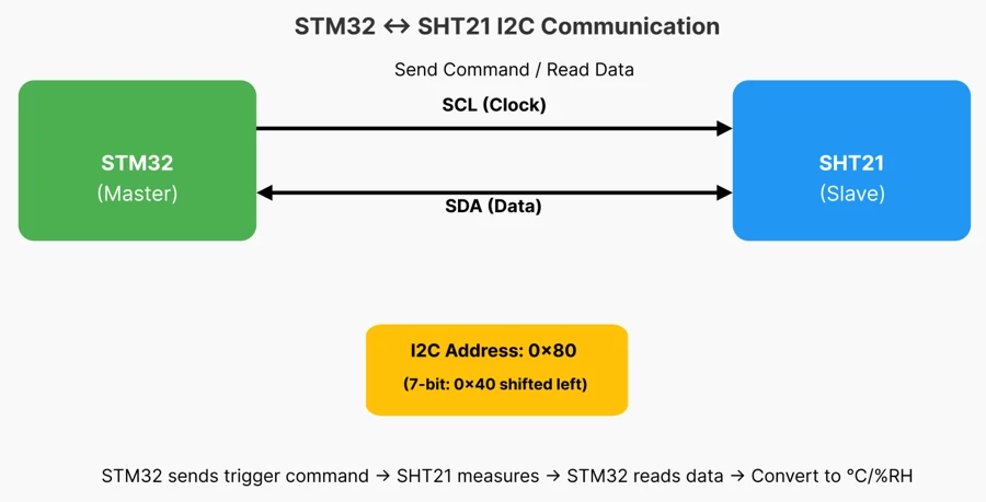
STM32 sends commands, SHT21 measures temperature and humidity, and returns the data via SDA line. The sensor I2C address is 0x80 (8-bit).
How STM32 Communicates with SHT21 via I2C
When interfacing SHT21 with STM32, the I2C peripheral in STM32 handles all the communication. Using the HAL library, you can easily send and receive data with just a few function calls.
Here’s how the communication process works:
- Initialization:
The STM32 initializes the I2C peripheral and sets up the SDA and SCL pins (PB7 and PB6 on the Blue Pill). - Sending Commands:
To start a measurement, STM32 sends one of the trigger commands (for example,0xF3for temperature).
This is done using the functionHAL_I2C_Master_Transmit(). - Waiting for Measurement:
In “No Hold Master” mode, the sensor takes up to 85 ms to complete the measurement.
The MCU waits or polls before reading the result. - Reading Data:
Once ready, STM32 reads the data bytes from the sensor usingHAL_I2C_Master_Receive().
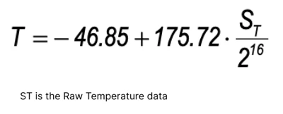
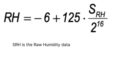
The sensor sends two data bytes (raw value) and one CRC byte. - Converting Data:
The raw values are then converted into real temperature (°C) and humidity (%RH) using formulas from the datasheet.
Because of this simple command-and-read process, the SHT21 sensor is one of the easiest I2C sensors to interface with STM32.
Hardware Requirements and Circuit Connection
Interfacing the SHT21 temperature and humidity sensor with STM32 requires a few essential components and proper wiring. This section covers everything you need to set up the hardware for this project.
Components Used in This Project
For this tutorial, you will need the following components:
- STM32F103C8 (Blue Pill) – 32-bit microcontroller to read sensor data.
- SHT21 Sensor Module – Digital temperature and humidity sensor.
- FT232 USB to UART Module – For logging data to the PC.
- Jumper Wires – To connect the sensor with STM32.
- Breadboard (optional) – For easy prototyping.
- Power Supply – 3.3V from STM32 or external regulated 3.3V source.
Tip: The SHT21 works at 3.3V logic, so avoid connecting it directly to 5V to prevent damage.
Circuit Diagram of SHT21 and STM32
The SHT21 communicates with the STM32 via the I²C protocol, which requires only two data lines: SDA (data) and SCL (clock). The FT232 module is used to monitor the data output on a serial console.
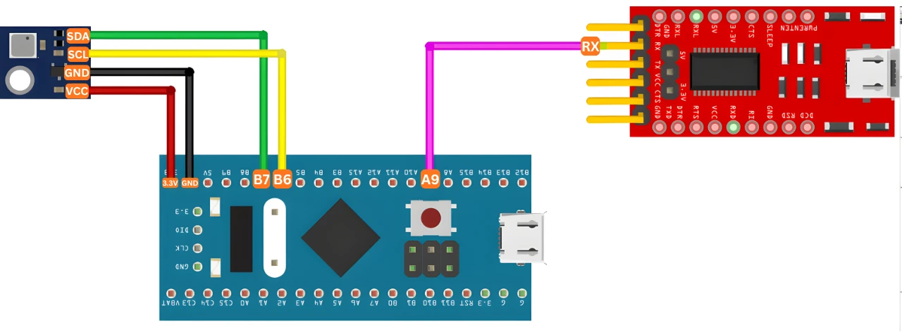
The Circuit diagram above shows SHT21 connected to STM32F103C8 via I²C and FT232 USB-UART for serial logging. The pin connections are explained below.
Pin Connection Details and Power Supply
Here’s how to wire the sensor to the STM32:
| SHT21 Pin | STM32 Pin | Description |
|---|---|---|
| VCC | 3.3V | Power supply (3.3V) |
| GND | GND | Ground |
| SDA | PB7 | I2C data line |
| SCL | PB6 | I2C clock line |
For the FT232 USB to UART module:
| FT232 Pin | STM32 Pin | Description |
|---|---|---|
| RX | PA9 | UART transmit from STM32 |
| GND | GND | Ground |
Note: The SHT21 only requires two pins for communication (SDA & SCL), making it very simple to interface. The power supply is provided by the STM32 3.3V pin, so no extra voltage regulator is needed.
STM32CubeMX Configuration
Before we can interface the SHT21 sensor with STM32, we need to configure the microcontroller using STM32CubeIDE and CubeMX. This section walks you through creating a new project, setting up the clock, enabling I2C and UART, and generating the initialization code.
STM32 Clock Configuration
We will start with configuring the clock for the project. The image below shows the STM32 clock configuration in the cubeMX.
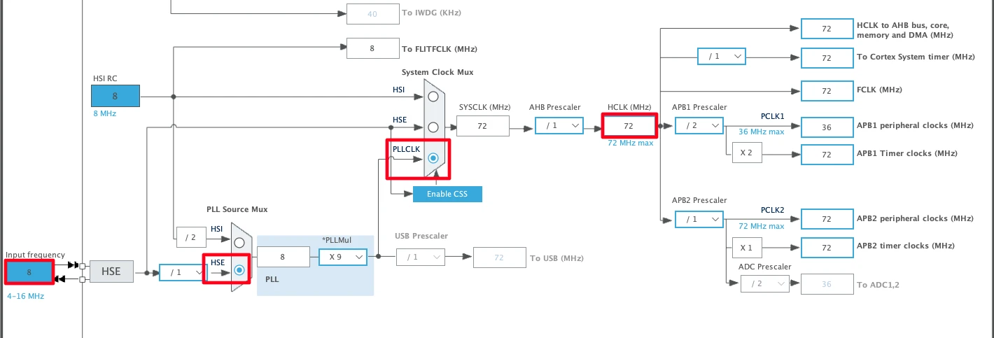
The STM32F103C8 has an external crystal of 8MHz. We will use the PLL to clock the system at maximum 72MHz.
STM32 I2C Configuration
Next, configure the I2C peripheral for the SHT21 sensor. The image below shows the I2C1 configuration in the cubeMX.
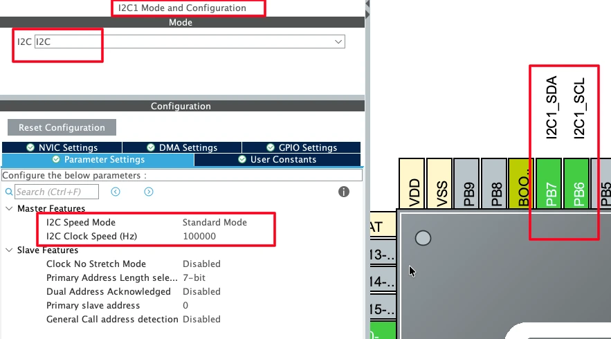
The SHT21 supports I2C clocks up to 400KHz, so we can use Normal Mode (100KHz) or Fast Mode (400 KHz). I have configured the I2C1 in the Normal Mode. The pins PB6 (I2C1_SCL) and PB7 (I2C1_SDA) are automatically configured.
STM32 UART Configuration
We need to configure the UART to view the logs on the serial console. These logs can be used to view the temperature and humidity results. Along with it, we can also enable the debug logs to debug the sensor in case of any issue.
The image below shows the UART1 configuration for the FT232 USB-to-UART module.
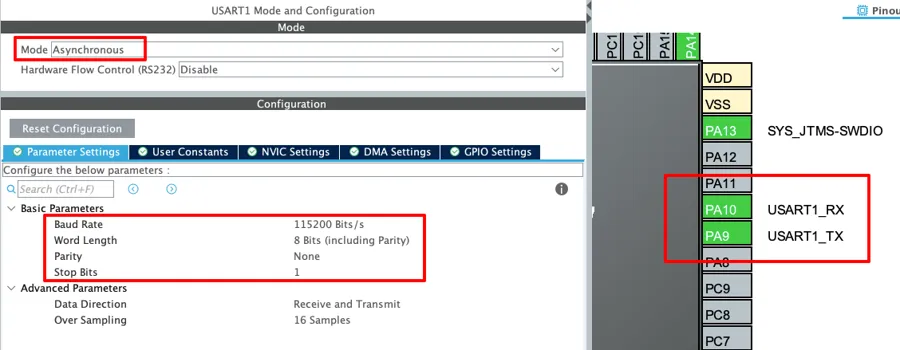
The UART1 is configured in the default state with baud rate of 115200, 8 data bits, 1 stop bit and no Parity. The pins PA9 (UART1_TX) and PA10 (UART1_RX) are configured automatically. Since we only need to transmit data to the FTDI, PA9 (UART1_TX) is connected to FTDI RX as mentioned in the wiring diagram.
Adding and Understanding the SHT21 Library
To simplify communication with the SHT21 temperature and humidity sensor, we use a prebuilt library. This section explains how to add the library to your STM32CubeIDE project and what each part of the library does.
Copying SHT21 Library Files to the Project
- Download the project from the bottom of this article and extract SHT21 library files (usually
sht21.handsht21.c) from the project. - Copy these files into your STM32CubeIDE project folder, inside src and inc subfolders.
Inside the SHT21 Header File (sht21.h)
The header file contains essential definitions and function prototypes for the SHT21 sensor:
- Function prototypes for initialization, reading temperature, and reading humidity.
- Macros and constants for sensor commands.
- Optional debug flags to enable logging on the serial console.
You generally do not need to modify the header file, except if you want to enable user logs or debug output.
// Enable or disable debug logs globally
#define SHT21_DEBUG  0
#define SHT21_USER 1Device Address and Command Definitions
- The SHT21 uses a 7-bit I²C address of
0x40. - The STM32 HAL library expects an 8-bit address, so the 7-bit address is shifted left by one, giving
0x80for write operations. - The header file also defines sensor commands such as:
- Trigger temperature measurement
- Trigger humidity measurement
- Soft reset
- Read/write user register
These definitions come directly from the SHT21 datasheet and make it easy to send commands to the sensor without remembering hexadecimal values.
Inside the SHT21 Source File (sht21.c)
By default the library uses I2C1 to communicate with SHT21 and UART1 to route the printf() data to console. If you are using any other instances of these peripherals, you need to define the correct ones in the beginning of the sht21.c file.
#define SHT21_I2C hi2c1
#define LOG_UART huart1Other than this change, you do not need to change anything else in this file.
How SHT21 Library Communicates using HAL I2C Functions
The library uses STM32 HAL I2C functions to communicate with the sensor:
HAL_I2C_Master_Transmit()→ Sends commands to the SHT21.HAL_I2C_Master_Receive()→ Reads data back from the sensor.
Below are the functions defined in the SHT21 library:
SHT21_Init()initializes the sensor.
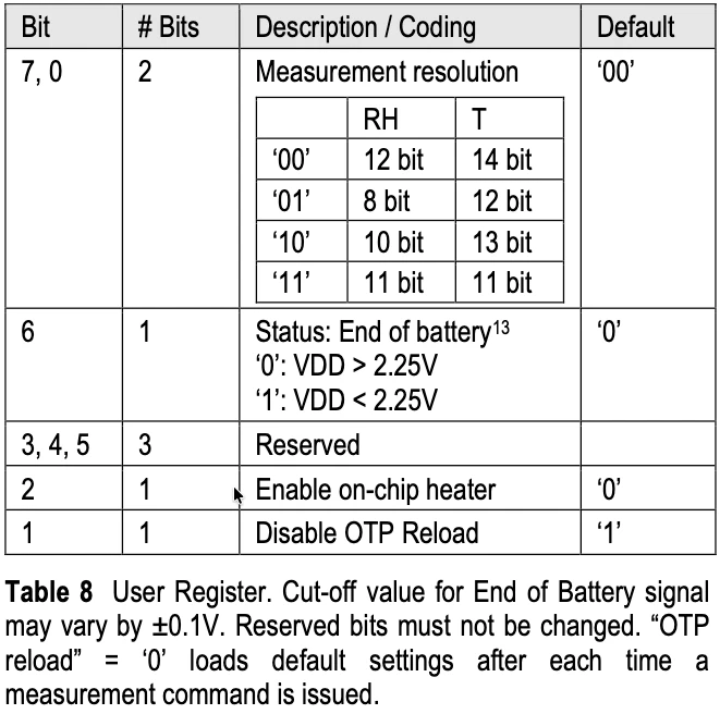
It simply call another functionSHT21_SoftReset()to reset the sensor to its default state. In this default state, the Temperature resolution is set to 14bits while the Humidity resolution is set to 12bits.SHT21_WriteUserRegister(uint8_t value)is used to modify the user register. This register contains the bits to configure the Temperature and Humidity resolutions, along with other functions like low battery alert, on chip heater etc.
SHT21_ReadRaw(uint8_t cmd, uint16_t *raw)is used to read the raw temperature or humidity data from the SHT21 sensor. Thecmdparameter specifies whether the function should read temperature or humidity, and the resulting data is stored in the variable pointed to byraw.SHT21_ReadTemperature(float *temperature)is used to first read the raw temperature data using the functionSHT21_ReadRaw. It will then convert this raw data to the temperature value in °C. The formula used for this conversion is mentioned in the datasheet of the SHT21 sensor.
The final temperature is stored in the variable pointed to bytemperature.
SHT21_ReadHumidity(float *humidity)is used to first read the raw humidity data using the functionSHT21_ReadRaw. It will then convert this raw data to the humidity value in %RH. The formula used for this conversion is mentioned in the datasheet of the SHT21 sensor.
The final temperature is stored in the variable pointed to byhumidity.
Example Main Code in STM32
Once the SHT21 library is added to the project and I2C/UART are configured, you can start writing the main code to read temperature and humidity from the sensor. This section explains how to include the library, read data, and print it on the serial console.
Including Library and Declaring Variables
- Include the SHT21 header file at the top of your
main.cfile:
#include "sht21.h"- Declare variables to store the temperature and humidity values:
float temp, hum;These variables will hold the converted Celsius and relative humidity (%) values read from the sensor.
Reading Sensor Data in Infinite Loop
Inside the main() function, initialize the library after everything else has finished initializing.
int main()
{
  ....
  ....
  /* USER CODE BEGIN 2 */
SHT21_Init();Inside the while(1) loop, call the library functions to read temperature and humidity:
while(1)
{
    // Read temperature and humidity
    SHT21_ReadTemperature(&temperature);
    SHT21_ReadHumidity(&humidity);

    printf("Temperature: %.2f °C, Humidity: %.2f %%\r\n", temperature, humidity);

    HAL_Delay(1000); // Delay 1 second between measurements
}Tip: Avoid reading data too frequently. The sensor needs at least 1 second between measurements for accurate readings.
Printing Data on UART Console
To display the readings on the serial console, use printf() or USER_LOG()
printf("Temperature: %.2f °C, Humidity: %.2f %%\r\n", temperature, humidity);- The
%.2fformat prints float values with two decimal places. - The double
%(%%) is required to correctly print the percentage symbol.
This allows you to monitor real-time temperature and humidity on your PC using a UART terminal like PuTTY or Tera Term.
Enabling Float with printf() in STM32CubeIDE
By default, printf() does not support float in STM32 projects. To enable it:
- Go to Project → Properties → C/C++ Build → Settings.
- Under MCU/MPU Settings, check “Enable float with printf”.
- Rebuild and flash the project.
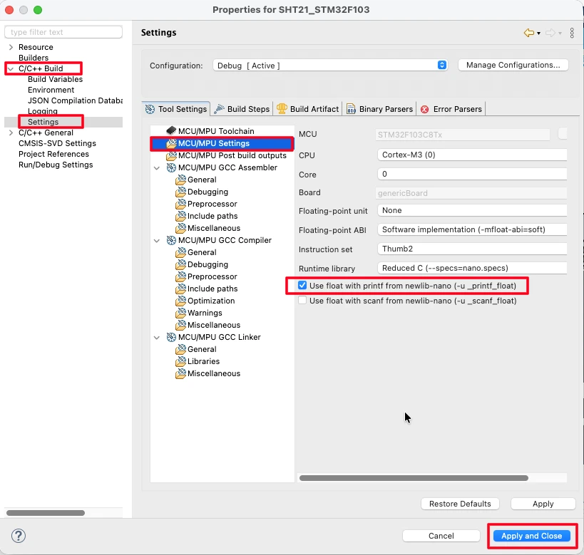
After enabling this option, float values like temperature and humidity will print correctly on the UART console.
Testing and Output Results
After configuring the hardware and writing the main code, the next step is to flash the code to the STM32 board and verify that the SHT21 sensor is reading temperature and humidity correctly.
Viewing Data on UART Serial Console
- Open a UART terminal like PuTTY or Tera Term.
- Connect to the STM32 UART port (PA9 → FT232 RX) with the correct baud rate (e.g., 115200).
- You should see real-time temperature and humidity readings printed every second:
Temperature: 25.34 °C, Humidity: 48.67 %Make sure the float with printf option is enabled in the project settings; otherwise, decimal values may not display correctly.
Sample Output and Live Data Changes
The gif below shows the temperature and humidity values on the console.

The temperature is rising because I am holding the sensor. It reaches to 32°C and start reducing when I released the sensor. The Humidity also behaves in the similar manner.
This confirms that the SHT21 sensor is working correctly and communicating via I²C with the STM32.
Video Tutorial
STM32 SHT21 Temperature & Humidity Sensor Video Tutorial
This tutorial demonstrates how to interface the SHT21 temperature and humidity sensor with the STM32 using the I2C protocol. Along with the detailed written guide, I’ve also prepared a hands-on video showing the complete setup, code, and testing process. Watch the video below and follow along with your own hardware.
Watch the STM32 SHT21 TutorialConclusion
In this tutorial, we successfully interfaced the SHT21 temperature and humidity sensor with an STM32 microcontroller using the I2C communication protocol.
We started by understanding the I2C basics, SHT21’s device address and command structure, and how the STM32 communicates with the sensor. Then, we configured the project in STM32CubeIDE, enabled I2C and UART peripherals, and added the SHT21 library to handle sensor communication efficiently.
We also explored the main code implementation, including reading raw sensor data, converting it to human-readable values, and displaying it via UART serial console. Finally, we tested the setup and observed live temperature and humidity changes from the SHT21 sensor.
This project demonstrates how easily the SHT21 can be integrated into embedded systems using STM32. You can extend this setup for:
- Environmental monitoring systems
- IoT weather stations
- Smart home applications
- Data logging projects
Browse More STM32 I2C Tutorials

How to interface MPU6050 (GY-521) with STM32

Interface SH1106 1.3″ OLED with STM32 via I2C
Send and Receive data from the WebServer using STM32
LCD 20X4 using I2C with STM32

Custom characters in LCD 1602 || STM32

GLCD 128×64 ST7920 interfacing with STM32
Interface AHT20 Sensor with STM32 Using I2C
STM32 SHT21 I2C Project Download
STM32 SHT21 FAQs
Subscribe
Login
0 Comments
Newest
