Last Updated: February 6, 2026
Implement LVGL on ESP32 SPI LCD
In this tutorial you will learn to interface an SPI LCD with ESP32 and display graphics using the LVGL library. This guide includes code, setup, and a working demo to enhance your projects. The project is available to download at the end of this post.
This is the 11th tutorial in the ESP32 series using the espressif-IDF and and 1st in the mini series covering SPI-LCDs in ESP32. In the previous tutorial we saw how to interface the SPI LCD display with ESP32 using the ESP’s built-in library.
Recommended Resources:
You should take a look at the following tutorials before continuing here:
VIDEO TUTORIAL
You can check the video to see the complete explanation and working of this project.
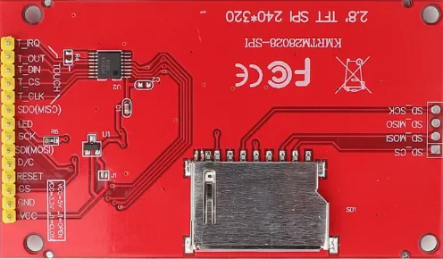
Introducing ILI9341 Display
The ILI9341 is a popular 2.4″ to 3.2″ TFT LCD display controller that supports 240×320 resolution and SPI interface. It’s often paired with the XPT2046 touch controller, enabling capacitive or resistive touch input. Together, they provide an affordable and efficient solution for graphical user interfaces in embedded systems like STM32 and ESP32.
Here are the important features of the ILI9341 Display:
- 240×320 pixel resolution with 262K color support
- SPI communication for both display (ILI9341) and touch (XPT2046)
- Integrated resistive touch support via XPT2046
- Compact size and low power consumption, ideal for embedded GUIs
Introducing LVGL
LVGL (Light and Versatile Graphics Library) is an open-source embedded graphics library designed to create modern and customizable graphical user interfaces (GUIs) for microcontrollers and small embedded systems. It enables developers to build intuitive and visually appealing interfaces on resource-constrained hardware like STM32, ESP32, and others with displays.
Here are the important features of LVGL:
- Lightweight & Efficient: Optimized for low-RAM, low-flash microcontrollers.
- Rich Widget Set: Includes buttons, sliders, charts, lists, keyboards, and more.
- Hardware Independent: Easily portable across different display drivers and platforms.
- Custom Themes & Styles: Allows creation of custom UI designs with theming support.
- Touch and Input Handling: Built-in support for touchscreens, keypads, and encoders.
- Animations: Supports smooth transitions and dynamic visual effects.
- Free and Open Source: Licensed under MIT, making it ideal for both hobby and commercial use.
WIRING DIAGRAM
Below is the image showing the connection between ESP32 and ILI9341.
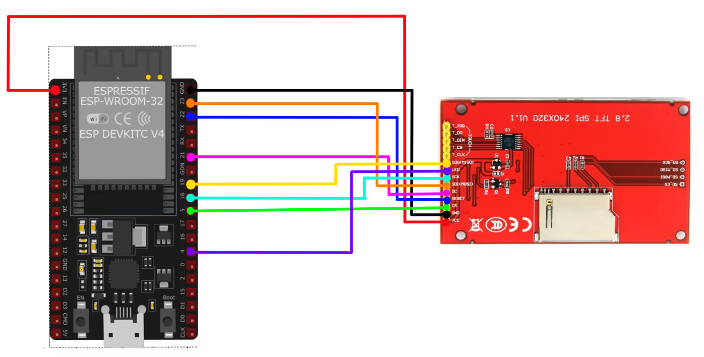
I am going to use the VSPI_HOST for the SPI. The SPI pins in the image above are defined according to it. You can check the SPI tutorial to know more about the available instances on ESP32.
| Pin Name | Function | Connected to |
|---|---|---|
| VCC | Power Supply (3.3V) | 3.3V |
| GND | Ground | GND |
| SDI / DI (MOSI) | SPI Data Input | GPIO23 |
| SDO / DO (MISO) | SPI Data Output | GPIO19 |
| SCK | SPI Clock | GPIO18 |
| DC / RS | Data/Command Select | GPIO21 |
| RESET | Reset Pin | GPIO22 |
| LCD_CS | Chip Select (LCD) | GPIO5 |
| LED | Backlight Control | GPIO4 / 3.3V |
INITIAL SETUP
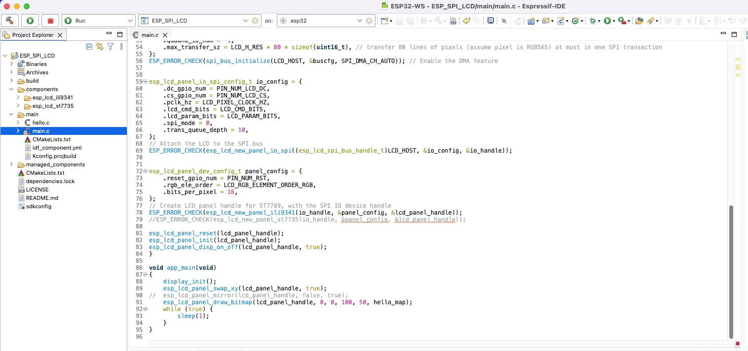
As I mentioned, we will continue with the project created in previous tutorial. Below is the same project I created.
Adding LVGL
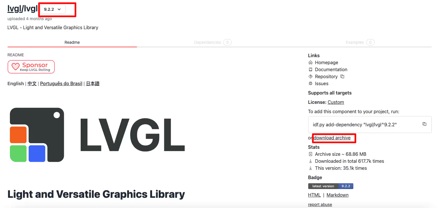
We will now add the LVGL related files to our project. Go to the https://components.espressif.com/ and search for LVGL. Download the component archive and extract it.
Now copy this extracted folder inside the component folder in the project.
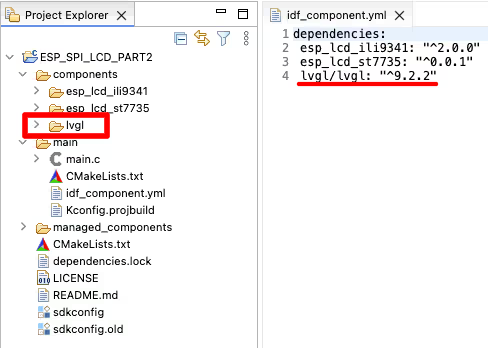
We need to link this component to our project. To do so, we will edit the file (idf_component.yml) inside the main folder and add the dependency of the LVGL component in this file. The LVGL version I am using is 9.2.2
Squareline Studio
We will use the Squareline Studio to design the UI for the display. Below are the steps for creating a simple UI on the studio.
First of all we need to create a project for the display resolution.
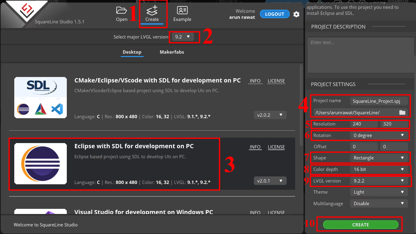
- Click on the Create Tab.
- Choose the LVGL Version. I have used the LVGL 9.2.2 component, so I am choosing the same version here.
- Click on Eclipse with SDL development for PC.
- Choose the project folder, where you want to store the files and also give some name to the project.
- Choose the display resolution. I am using 2.8″ LCD with resolution 240×320.
- Select the display rotation. I am not rotating the display.
- Select the display shape.
- Select colour depth. RGB565 uses 16bit, hence I am choosing it.
- Choose the LVGL version.
- Click on Create to create the project.
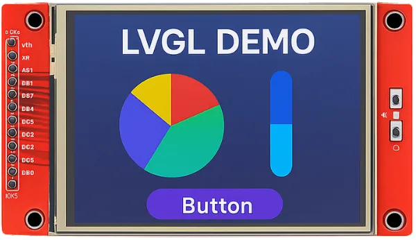
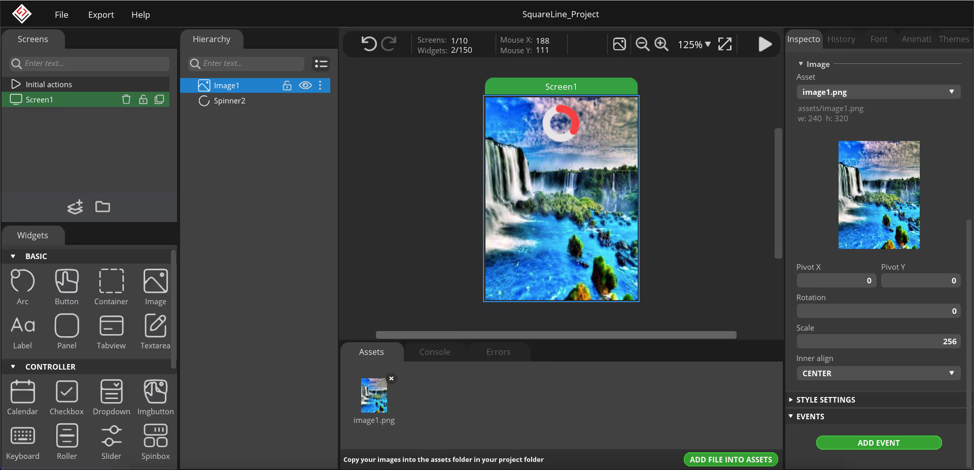
Next we will design the UI on the studio. I am going to create a very basic looking UI. You can watch the video at the end of this post to see how I have designed it. Below is the image showing the final UI.
Now we will export the UI files. To do so, first open the File->Project Settings and modify the UI Path and LVGL path as shown in the image below.
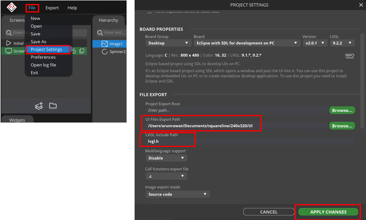
The UI Export path is where the UI files will be extracted to. I have created a folder named UI inside the project folder. This is where the UI files will be exported to. Also add lvgl.h in the LVGL include path.
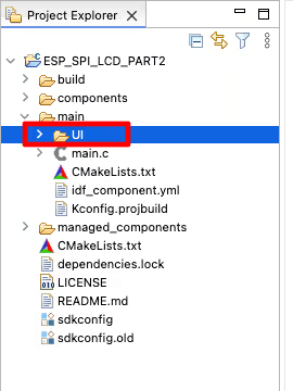
Next copy the generated UI folder inside the main folder.
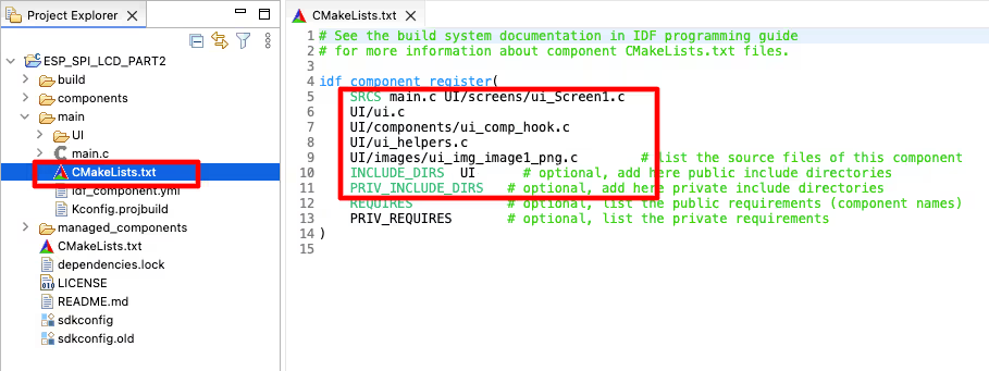
The UI files will not be recognised by the project. We need to manually include the source files in our project make file. Open the CMakeLists.txt file inside the UI folder and copy all the source files from here.
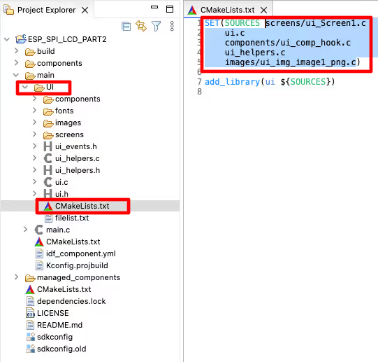
Now open the CMakeLists.txt file inside the main folder and paste the copied source files along with the main.c. Also include the folder UI in the INCLUDE_DIRS. We need to provide an additional path UI/*** in front of the source files because we are including these in the main folder.
THE CODE
Inclusions
We will add some more inclusions to our previously created project.
#include "lvgl.h"
#include <sys/lock.h>
#include <sys/param.h>
#include <esp_timer.h>
#include "UI/ui.h"LVGL related functions
static bool notify_lvgl_flush_ready(esp_lcd_panel_io_handle_t panel_io, esp_lcd_panel_io_event_data_t *edata, void *user_ctx)
{
    lv_display_t *disp = (lv_display_t *)user_ctx;
    lv_display_flush_ready(disp);
    return false;
}The function notify_lvgl_flush_ready is called by the ESP display when the colour data is ready to be flushed on the display. Inside this function we will simply call the lv_display_flush_ready function to inform the LVGL that the color data is ready to be flushed.
static void lvgl_flush_cb(lv_display_t *disp, const lv_area_t *area, uint8_t *px_map)
{
    lvgl_port_update_callback(disp);
    esp_lcd_panel_handle_t panel_handle = lv_display_get_user_data(disp);
    int offsetx1 = area->x1;
    int offsetx2 = area->x2;
    int offsety1 = area->y1;
    int offsety2 = area->y2;
    // because SPI LCD is big-endian, we need to swap the RGB bytes order
    lv_draw_sw_rgb565_swap(px_map, (offsetx2 + 1 - offsetx1) * (offsety2 + 1 - offsety1));
    // copy a buffer's content to a specific area of the display
    esp_lcd_panel_draw_bitmap(panel_handle, offsetx1, offsety1, offsetx2 + 1, offsety2 + 1, px_map);
}The function lvgl_flush_cb is the Flush callback. This function is responsible for flushing the colour data on the display area. Inside this function we will first call the function lvgl_port_update_callback to update the display resolution.
Then this function will call esp_lcd_panel_draw_bitmap to draw the color data on the required display area.
static void lvgl_tick(void *arg)
{
    /* Tell LVGL how many milliseconds has elapsed */
    lv_tick_inc(LVGL_TICK_PERIOD_MS);
}The tick function will be used to call the lv_tick_inc to tell LVGL how many milliseconds has elapsed so far. The LVGL_TICK_PERIOD_MS is set to 2ms.
static void lvgl_port_task(void *arg)
{
    uint32_t time_till_next_ms = 0;
    uint32_t time_threshold_ms = 2000 / CONFIG_FREERTOS_HZ;
    while (1) {
        _lock_acquire(&lvgl_api_lock);
        time_till_next_ms = lv_timer_handler();
        _lock_release(&lvgl_api_lock);
        // in case of triggering a task watch dog time out
        time_till_next_ms = MAX(time_till_next_ms, time_threshold_ms);
        vTaskDelay(time_till_next_ms);
    }
}The LVGL task will be used to call the lv_timer_handler every few milliseconds. We need to use the mutex here as the LVGL functions are not thread safe.
The main function
Inside the main function we will initialise the LVGL after initialising the display driver.
void app_main(void)
{
    display_init();
lv_init(); /*Initialize LVGL library*/Then we will create a LVGL display with the screen resolution. After creating the display, we will create buffers to store the LVGL color data. I am using double buffer here, so the LVGL can draw into one buffer while the content of the other buffer is sent to the display in the background. This way, the rendering and refreshing of the display become parallel operations.
    // create a lvgl display
    lv_display_t *display = lv_display_create(LCD_H_RES, LCD_V_RES);

    // alloc draw buffers used by LVGL
    // it's recommended to choose the size of the draw buffer(s) to be at least 1/10 screen sized
    size_t draw_buffer_sz = LCD_H_RES * 20 * sizeof(lv_color16_t);
    void *buf1 = spi_bus_dma_memory_alloc(LCD_HOST, draw_buffer_sz, 0);
    void *buf2 = spi_bus_dma_memory_alloc(LCD_HOST, draw_buffer_sz, 0);
    // initialize LVGL draw buffers
lv_display_set_buffers(display, buf1, buf2, draw_buffer_sz, LV_DISPLAY_RENDER_MODE_PARTIAL);Next we will associate the lcd_panel_handle with the LVGL display. This will connect our ESP LCD driver with the LVGL display driver. Then we will set the colour format to RGB565. Also set the flush callback to lvgl_flush_cb. We have already defined this callback function outside the main function. I am also setting the rotation of the display to 180 degrees.
    // associate the mipi panel handle to the display
    lv_display_set_user_data(display, lcd_panel_handle);

    // set color depth
    lv_display_set_color_format(display, LV_COLOR_FORMAT_RGB565);

    // set the callback which can copy the rendered image to an area of the display
    lv_display_set_flush_cb(display, lvgl_flush_cb);

lv_display_set_rotation(display, LV_DISPLAY_ROTATION_180);Now we will create a ESP timer for the LVGL tick functionality. The callback function for this timer is lvgl_tick, which is already defined outside the main function. Start this timer to run periodically.
    /*nstall LVGL tick timer*/
    // Tick interface for LVGL (using esp_timer to generate 2ms periodic event)
    const esp_timer_create_args_t lvgl_tick_timer_args = {
        .callback = &lvgl_tick,
        .name = "lvgl_tick"
    };
    esp_timer_handle_t lvgl_tick_timer = NULL;
    ESP_ERROR_CHECK(esp_timer_create(&lvgl_tick_timer_args, &lvgl_tick_timer));
ESP_ERROR_CHECK(esp_timer_start_periodic(lvgl_tick_timer, LVGL_TICK_PERIOD_MS * 1000));Next we will register the callback for the event, when the colour data is ready to be flushed. This callback function notify_lvgl_flush_ready, is already defined outside the main function.
    /*Register io panel event callback for LVGL flush ready notification*/
    const esp_lcd_panel_io_callbacks_t cbs = {
        .on_color_trans_done = notify_lvgl_flush_ready,
    };
ESP_ERROR_CHECK(esp_lcd_panel_io_register_event_callbacks(io_handle, &cbs, display));Next we will run the UI created by the squareline studio. The function ui_init() is in the UI file generated by the studio. We also need to lock the mutex before running the UI.
     /* Run the UI */
    // Lock the mutex due to the LVGL APIs are not thread-safe
    _lock_acquire(&lvgl_api_lock);
    ui_init();
_lock_release(&lvgl_api_lock);Finally we will create a LVGL task with a bigger stack size. This task will call the lv_timer_handler() to manage the LVGL tick functionality.
    /*Create LVGL task*/
    xTaskCreate(lvgl_port_task, "LVGL", 4*4096, NULL, 2, NULL);

	while (1)
	{
		vTaskDelay(1000/portTICK_PERIOD_MS);
	}
}RESULT
Below is the gif showing the output of the project.
You can see the image has been loaded onto the display and the spinner is rotating as well.
