

Home ▸ Uncategorized ▸
Updated On: October 28, 2026
CANopen with STM32: Heartbeat and Emergency Messages
This is Part 9 of the CANopen with STM32 series. In Part 8, we used the TPDO protocol so that the STM32 node could send a potentiometer value and the LED states to the master on its own. The master now receives process data from the node, but it still cannot tell whether the node is functioning properly, or is there any fault in the node.
In this part, we cover the CANopen heartbeat and emergency messages. The heartbeat message tells the master that the node is alive and shows its NMT state, while the emergency message reports an error as soon as it happens. We will look at how both messages work, change the heartbeat rate in the object dictionary, and send an emergency message when the potentiometer value crosses a limit. I am using the same STM32H562 project from the earlier parts of this series.
This is Part 9 in the STM32 CANopen series.
Table of contents
How the Heartbeat Works
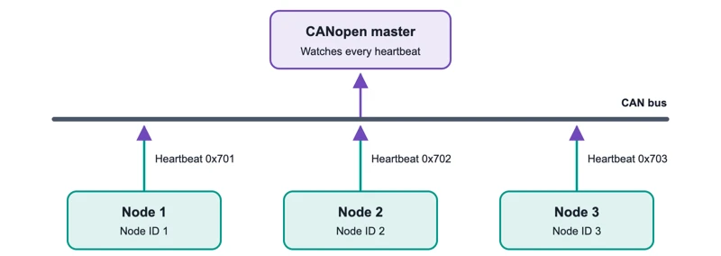
A CANopen network usually contains many nodes, and the master needs to know whether each one is still alive. A node can fail without any warning, and a node that has lost power cannot report anything by itself. For this reason, CANopen uses the heartbeat message. Each node sends it again and again after a fixed time, without waiting for any request from the master, and the master treats a missing heartbeat as a sign of trouble. The node may have lost power, it may have crashed, or its cable may be disconnected. The heartbeat is also lighter on the bus than the older node guarding method, because the master does not have to send a request to every node.
Heartbeat Message Format
The heartbeat uses the COB-ID 0x700 plus the Node ID and carries a single data byte. A Node ID can be from 1 to 127, so the heartbeat identifiers range from 0x701 to 0x77F. These identifiers are high numbers, which means that they have a low priority on the CAN bus, so the heartbeat does not delay the more important PDO messages. The data byte holds the current NMT state of the node, so the master learns that the node is alive and also which state it is in. The table below lists the possible values.
| Data byte | Meaning |
|---|---|
0x00 | Boot-up message, sent once after initialization |
0x04 | Stopped |
0x05 | Operational |
0x7F | Pre-operational |
Boot-Up Message
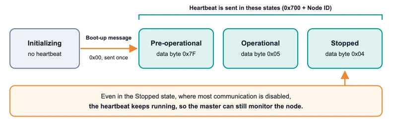
The value 0x00 belongs to the boot-up message. A node sends this message once, at the moment its initialization is finished and before it starts sending heartbeats. It uses the same COB-ID as the heartbeat, which is 0x700 plus the Node ID. The message carries one data byte with the value 0x00, and this value is used only for the boot-up message, because no NMT state uses it.
The boot-up message tells the master that the node has just started. This is useful because the master can learn about a node that has been powered on, reset, or recovered after a failure. For example, if a node loses power and then restarts, the master sees a new boot-up message and understands that the node has restarted and may need to be configured again. After the boot-up message, the node enters the pre-operational state, and the regular heartbeat starts with the data byte 0x7F.
Heartbeat in NMT States
The heartbeat is sent in the pre-operational, operational and stopped states, but not while the node is still initializing. After the initialization, the node enters the pre-operational state on its own, and the master can then move it to the operational or the stopped state with an NMT command. The stopped state needs attention, because most communication is disabled there, and only the NMT commands and the heartbeat remain active. Since the heartbeat keeps running in this state, the master can still monitor the node.
How CANopen EMCY Messages Work
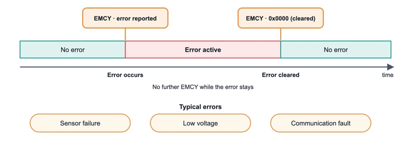
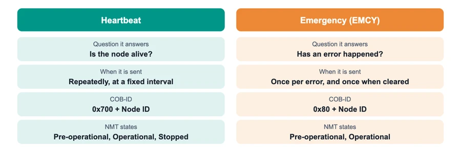
The heartbeat shows that a node is alive, but it does not report problems inside the node. A node can be alive and still have a failed sensor, a low supply voltage or a broken communication link, and the heartbeat alone cannot show any of this. The emergency message, also called the EMCY message, is used for this purpose. When a node detects an internal error, such as a sensor failure, a low voltage or a communication fault, it sends an EMCY message immediately, without waiting for any request. Unlike the heartbeat, it is not periodic. The node sends it once when the error occurs, and the standard defines a second message with the error code 0x0000 for the moment when the error is cleared. The example in this part reports only the occurrence of the error.
EMCY Frame Format
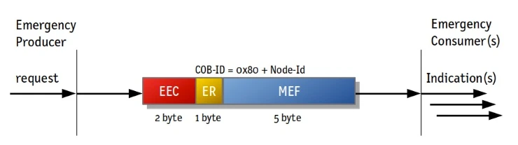
The EMCY message uses the COB-ID 0x80 plus the Node ID and carries eight data bytes. The first two bytes hold the emergency error code, also called the EEC, which tells the master the type of error. The third byte is the error register (ER), which gives the general category of the error. The remaining five bytes are manufacturer specific, so the standard does not define their meaning, and we can use them for extra information such as a sensor number or a measured value. The picture below shows how these eight bytes are arranged.

The error code is sent with the low byte first, so byte 0 is the least significant byte and byte 1 is the most significant byte. The values in the picture are only placeholders, and the frame in our test shows different values.
The CiA 301 standard defines common groups of error codes, for example 0x2000 for current errors and 0x3000 for voltage errors. Master can use these groups to understand the error even if it does not know our application. The value 0x1234 that we use later is only an example for this tutorial, and it is not a code from the standard.
Error Register
The error register is one byte stored at index 0x1001 of the object dictionary. Each bit represents a general type of error. Bit 0 stands for a generic error, bit 1 for a current error, bit 2 for a voltage error, bit 3 for a temperature error and bit 4 for a communication error. Bit 5 is defined by the device profile, bit 6 is reserved, and bit 7 is manufacturer specific.
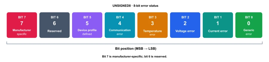
The matching bit is set when an error occurs, so the register gives the master the error category, while the error code gives the detail. In our test, the register shows the value 1, which means that only bit 0, the generic error bit, is set.
When the Message Is Sent
The EMCY message can be sent in the pre-operational and operational states, but not in the stopped state, because the node is not allowed to transmit it there. Its COB-ID is stored at index 0x1014 with the default value 0x80, and the stack adds the Node ID, which is why we will see the identifier 0x81 in the test. The standard also defines an inhibit time for the EMCY message at index 0x1015, which sets the minimum gap between two EMCY messages from the same node. We do not need it in this part, because our code already sends the message only once for each fault.
Test the CANopen Heartbeat on STM32
Before we change anything, we will look at the output of the current project. I have already opened the previous project in STM32CubeIDE and the TSMaster software on my Windows virtual machine. After I press the Start button, TSMaster connects to the CAN bus. The heartbeat comes from the CANopen library and not from our application code, so we do not need to add anything to the project to see it.
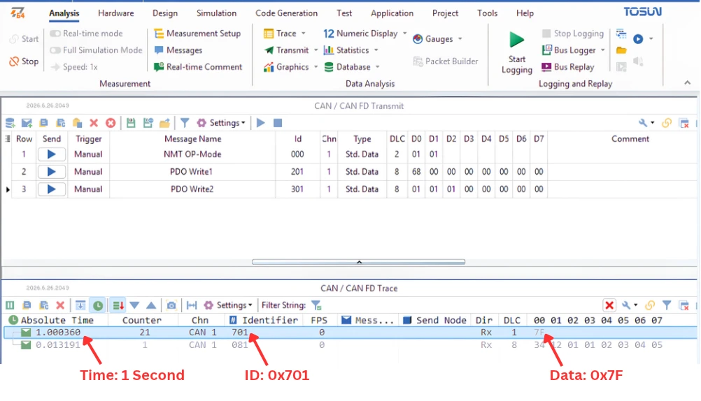
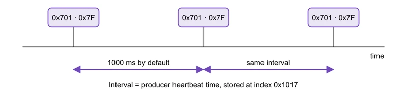
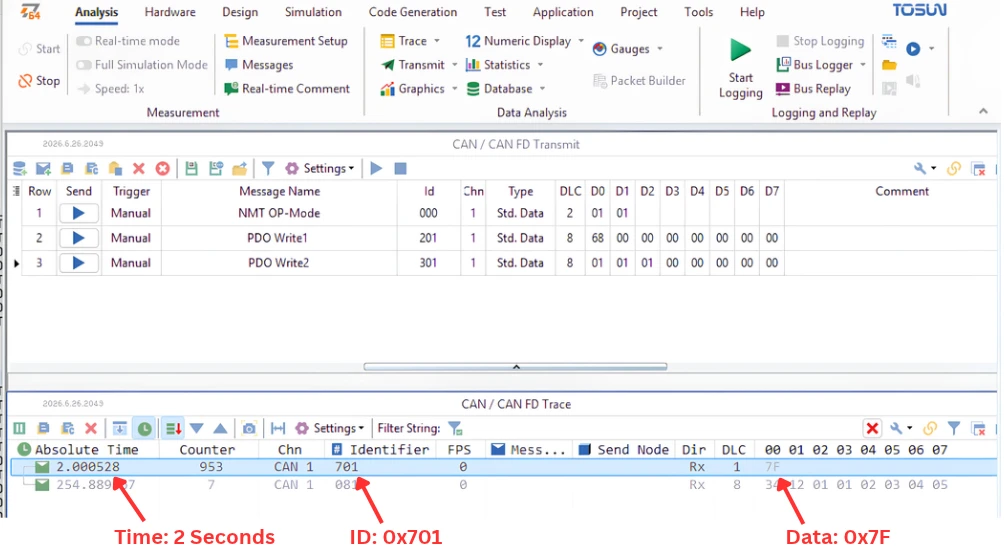
The heartbeat message appears every second with the identifier 0x701, which is 0x700 plus our Node ID of 1. The data byte is 0x7F, so the node is in the pre-operational state. We have not sent any NMT command yet, so the node stays in this state after the start-up.
CANopen Heartbeat Object Dictionary
To see the heartbeat configuration, go to the Middlewares -> Thrid_party -> emotas_CANopen -> emotas -> Config folder, and open the emotas_CANopen_Slave.html file in a browser. This file lists all the objects of our node, with their indexes, data types and default values, in HTML format. The indexes 0x1016 and 0x1017 are reserved for the heartbeat.
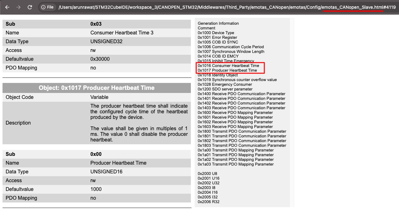
Producer Heartbeat Time
Index 0x1017 is the producer heartbeat time. It sets the time in milliseconds between two heartbeat messages that our device produces. The default value is 1000, which is why the node sends a heartbeat every second, and a value of zero disables the heartbeat. The node produces this heartbeat on its own, so no application code is needed. A shorter time lets the master notice a failure faster, but it also adds more frames to the bus. A master that monitors this node normally uses a time limit that is somewhat larger than the producer time, so that one delayed frame does not cause a false alarm.
Consumer Heartbeat Time
Index 0x1016 is the consumer heartbeat time, and it works in the opposite direction. Our node uses it to monitor the heartbeat messages of other nodes. Each entry holds the Node ID to monitor in bits 16 to 23 and the maximum time in milliseconds in the lower 16 bits. For example, the value 0x00050BB8 would monitor the node with Node ID 5 and expect its heartbeat at least every 3000 milliseconds. The node treats a late heartbeat as a problem with that node. The generated entries have a time of zero, so no node is monitored. We only need the producer time in this part, so 0x1016 stays unchanged.
Change the Heartbeat Time
To change the value of 0x1017, we open the generated file gen_objdict.c and scroll to the object description section. The last field of the 0x1017:0 descriptor is not the heartbeat time itself, but a position in the 16-bit constant array od_const_u16, where the real values are stored. Originally this field is 1, and position 1 of the array holds 1000, so the node sends a heartbeat every second. This means that we change the heartbeat rate by choosing a different position, and we do not type the new time into the descriptor.
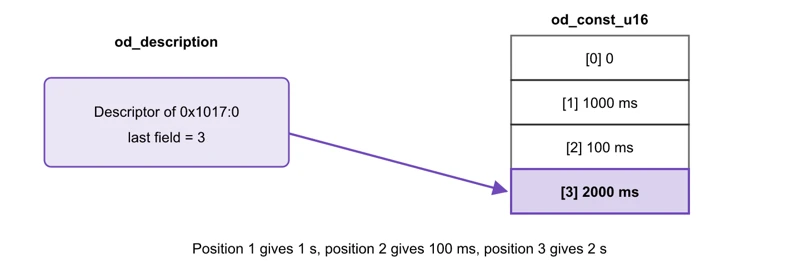
Other objects use the same array. For example, the inhibit time of TPDO 2 points to position 1, so we should not edit the existing values. We should select another position, or add a new value at the end of the array.
Add a Custom Value
If the value that we need is not in the array, we add it ourselves. For a heartbeat every two seconds, add the value 2000 at the end of the array and increase the array size by one, so that the array has space for the new element. The new value sits at position 3, so change the last field of the descriptor to 3.
static CO_CONST UNSIGNED16 CO_CONST_STORAGE_CLASS	od_const_u16[2+1+1] = {
	(UNSIGNED16)0u,
	(UNSIGNED16)1000u,  // 1
	(UNSIGNED16)100u,   // 2
	(UNSIGNED16)2000u}; // 3

/* Descriptor of 0x1017:0, the last field is now 3 */
{ (UNSIGNED8)0u, CO_DTYPE_U16_ERRCTRL, (UNSIGNED16)4119u, CO_ATTR_NUM | CO_ATTR_READ | CO_ATTR_WRITE | CO_ATTR_DEFVAL, (UNSIGNED16)3u},/* 0x1017:0*/After flashing the project again, the heartbeat messages arrive every two seconds, as configured. We can use any value that suits the application in the same way, as long as it fits in the 16-bit array.
Send a CANopen EMCY on an ADC Fault
To see how the library handles the EMCY message, open the CANopen library PDF that is provided with the library setup and browse to section 3.12, which is titled EMCY. The document describes the emergency message as a protocol that devices use to signal errors or warnings.
To simulate an error, we use the potentiometer from the previous part. The main loop already calls adcUpdate, which stores the result in the variable adcValue. A real application would check a real fault, such as an overheating sensor or a low supply voltage, but a potentiometer lets us create the fault by hand at any time. We treat a value close to the upper limit of the 12-bit range as the error condition, and the threshold is 0x0FF0, which is 4080 out of a maximum of 4095. The code below goes into the main loop of main.c.
  while (1)
  {
    /* USER CODE END WHILE */

  MX_CANopen_Process();
    /* USER CODE BEGIN 3 */

  adcUpdate();

  uint8_t emcyData[5];
  static int adcFaultActive = 0;

  if (adcValue >= 0x0FF0)
  {
      emcyData[0] = (uint8_t)(adcValue & 0xFF);
      emcyData[1] = (uint8_t)(adcValue >> 8);
      emcyData[2] = 0;
      emcyData[3] = 0;
      emcyData[4] = 0;

      /* Report only when the fault first occurs. */
      if (!adcFaultActive)
      {
          adcFaultActive = 1;
          coEmcyWriteReq(0x1234, emcyData);
      }
  }
  else
  {
      /* The ADC threshold fault has cleared. */
      adcFaultActive = 0;
  }

	  if ((nmtState == CO_NMT_STATE_OPERATIONAL) && (CANState == CO_CAN_STATE_BUS_ON))
	  {
		  Application_Process();
		  HAL_GPIO_WritePin(GPIOA, GPIO_PIN_1, led1);
		  HAL_GPIO_WritePin(GPIOA, GPIO_PIN_2, led2);
		  HAL_GPIO_WritePin(GPIOA, GPIO_PIN_3, led3);
		  led1Read = HAL_GPIO_ReadPin(GPIOA, GPIO_PIN_1);
		  led2Read = HAL_GPIO_ReadPin(GPIOA, GPIO_PIN_2);
		  led3Read = HAL_GPIO_ReadPin(GPIOA, GPIO_PIN_3);
		  my_pdo_update_callback(2);
	  }
}I have moved the adcUpdate call and the emergency block outside that if condition. Reading the ADC can take place at any point in the program, and only the transmission of the TPDO data depends on the operational state. The LED and TPDO code stays inside the condition, because it still needs the operational state.
Define the Variables
The array emcyData holds the five bytes of manufacturer-specific data. The static variable adcFaultActive remembers whether the message has already been sent for the current fault. The main loop runs many times every second, so without this flag the node would send the same message again and again while the potentiometer stays above the threshold, and the repeated frames would fill the bus.
Build the Data and Send the Message
When the ADC value reaches the threshold, we store it in the first two bytes of the manufacturer-specific data, with the low byte first, and set the remaining three bytes to zero. We send the ADC value in these bytes so that the master can see the value that caused the error. If the flag is still zero, we set it to 1 and call coEmcyWriteReq with the error code 0x1234 and the data array. When the value falls below the threshold, the else branch clears the flag, so the message can be sent again the next time the limit is crossed.
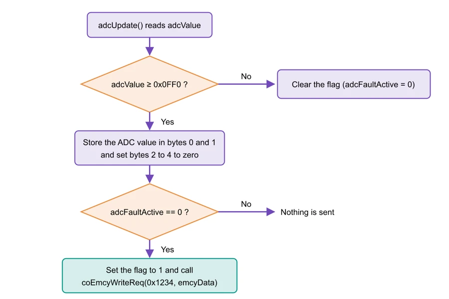
Note that the else branch clears only our own flag. It does not send the error-reset message that the standard defines, and a complete application would also report that the error has gone.
Test the CANopen EMCY Message
The EMCY message can be transmitted in pre-operational mode as well. But I want you to see the current ADC value, which is only possible when the node is operational. For this reason, I send the NMT Start command from TSMaster to put the node into the operational state. This is required only for the TPDO, and the emergency message itself does not need this state.
When the ADC value is lower than the threshold, no EMCY message is sent by the node. When the value crosses the threshold, one emergency message appears immediately, with the identifier 0x81. The first two bytes are the error code 0x1234, which appears as 34 12 because CANopen sends the low byte first. The next byte is the error register, and its value is 1. The following two bytes hold the ADC value at the moment of crossing, again with the low byte first, and the last three bytes are zero.
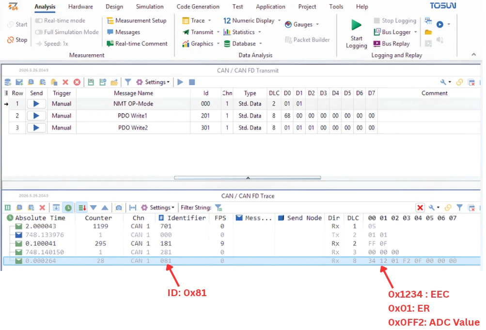
When the potentiometer is turned below the threshold, and then again towards the upper limit once more, the node sends a new emergency message. This confirms that the flag was cleared when the value fell below the threshold and that each crossing of the threshold produces exactly one message.
Conclusion
In this tutorial, we implemented the CANopen heartbeat and emergency messages on the STM32 node. We controlled the heartbeat rate through the producer heartbeat time at index 0x1017, either by selecting an existing value from the constant array or by adding our own value and pointing the descriptor to it. We also sent an emergency message with coEmcyWriteReq when the potentiometer value crossed a threshold, and a flag made sure that the message was sent only once for each fault. The message works in the pre-operational state as well, because it does not depend on the operational state.
Together, the two messages give the master a complete picture of the node. The heartbeat shows that the node is still running and which state it is in, and the EMCY message shows what went wrong.
Download Project Here
Download the CubeMX project files and HAL source code — all tested on real hardware.
If you find this useful, you can support us with a Donation as well.
Browse More STM32 CANopen Tutorials

Subscribe
Login
0 Comments
Newest

