
Home ▸ Uncategorized ▸
Updated On: October 16, 2026
CANopen with STM32: TPDO Protocol Explained
This is Part 8 of the CANopen with STM32 series. In Part 7, we connected CANopen objects to STM32 variables and used two RPDOs to control three LEDs from the CANopen master. In that case, the data always moved in one direction, from the master to the STM32 node.
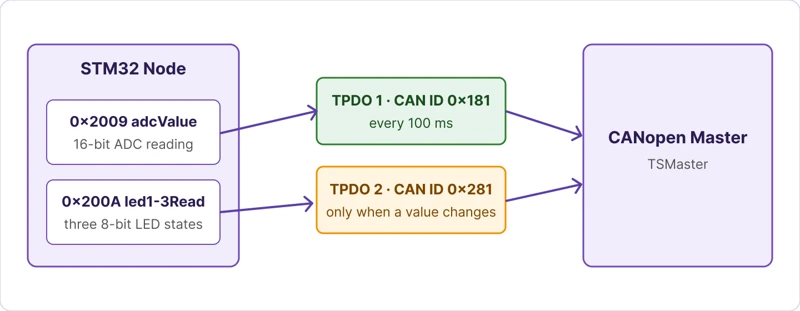
In this part, we reverse the direction and use the TPDO protocol, so the STM32 node can send data to the master on its own. We will create two TPDOs. The first one sends the value of a potentiometer, which is read through the ADC, every 100 milliseconds. The second one sends the states of the three LEDs, but only when one of them changes. I am using the same STM32H562 project from the earlier parts of this series.
This is Part 8 in the STM32 CANopen series.
Table of contents
How the CANopen TPDO Protocol Works
The TPDO protocol works in the same way as the RPDO protocol, just with the direction reversed. The STM32 node transmits the data, and the master receives it. A TPDO is also not limited to a single object, because we can map several objects into one message and send them together in the same CAN frame.
A TPDO can be triggered in different ways.
- In continuous transmission, the node continuously sends the data after a fixed period of time.
- In transmission on change, the node sends the TPDO only when the value of a mapped object changes.
- The third method uses the SYNC message, and it will be covered in a later part of the series.
Here, TPDO 1 uses the continuous method and TPDO 2 uses the on-change method, as the diagram below shows.
Set Up the ADC in STM32CubeMX
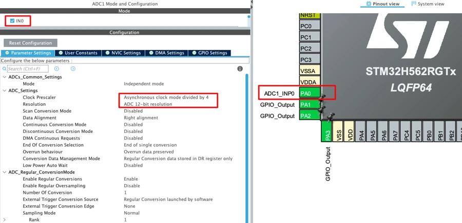
In STM32CubeMX, enable channel 0 of ADC1, which configures pin PA0 as the ADC input for the potentiometer. We leave all the other settings at their default values, because we will read the ADC in polling mode. The resolution stays at 12 bits, so the ADC value ranges from 0 to 4095.
Regenerating the code rewrites the whole CANopen library, and we would lose every change that we made for the RPDOs. To avoid this, copy the CANopen configuration folder (Config) of the current project to a safe location before generating the code. After the code is generated, delete the new configuration folder from the project and copy the saved folder back in.
Configure TPDOs in CANopen Device Designer
I am using the evaluation version of CANopen Device Designer, which limits the size of the project. For this reason, I will create a new project, generate the files from it, and then carry the changes into our STM32 project.
Add Two TPDOs
Open the object dictionary, click on the communication segment, and add a CANopen service of type PDO. Select the transmit direction, set the PDO count to 2, and choose dynamic mapping. Keep the transmission type at 254, which means the TPDO is event driven and does not depend on the SYNC message. Enable the inhibit time and the event timer, and leave both values at zero for now.
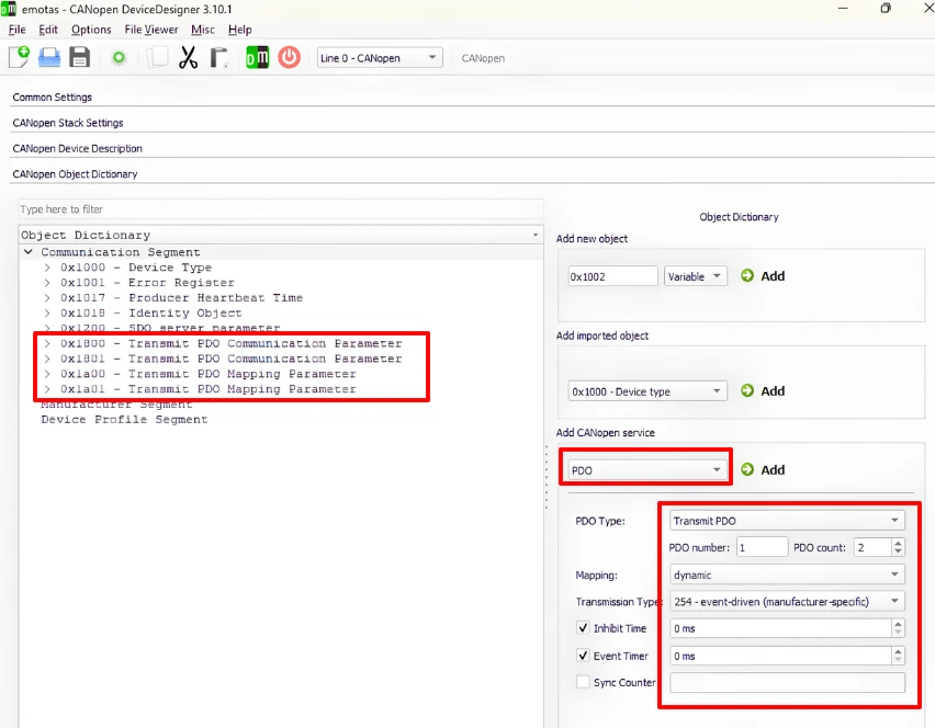
The designer adds four new objects. The indexes 0x1800 and 0x1801 are the TPDO communication parameters, and the indexes 0x1A00 and 0x1A01 are the TPDO mapping parameters.
Create the Objects
The STM32 project that we are continuing from Part 7 already contains two manufacturer objects that we added there. The object at 0x2007 is the variable my_variable, and the object at 0x2008 is the array that holds led1, led2 and led3, which the RPDOs use to control the LEDs. Because these indexes are taken, the new objects for this part start at 0x2009. Keep in mind that the Device Designer project we create in this part is a fresh one, so it does not contain the earlier objects, and the indexes 0x2009 and 0x200A are chosen to avoid a clash when we copy the generated code into our STM32 project.
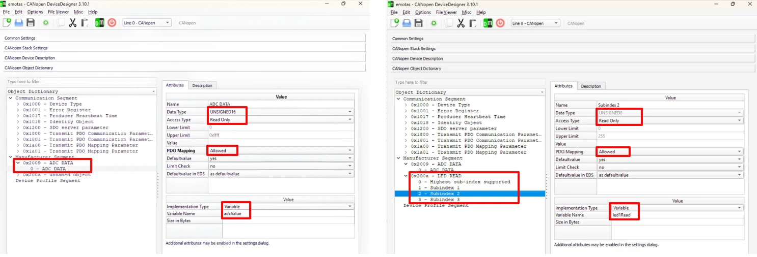
The first object (0x2009) is a variable named ADC Data, and the second one (0x200a) is an array named LED Read that holds the three LED states. The variable name of each subindex must match the variable that we define in the STM32 code. The master only need to read these values, so we set the access type to read only. Also set the PDO mapping to allowed, since an object cannot be mapped into a TPDO without it.
| Index | Subindex | Variable Name | Data Type | Access | PDO Mapping |
|---|---|---|---|---|---|
0x2009 | 0 | adcValue | Unsigned 16-bit | Read only | Allowed |
0x200A | 1 | led1Read | Unsigned 8-bit | Read only | Allowed |
0x200A | 2 | led2Read | Unsigned 8-bit | Read only | Allowed |
0x200A | 3 | led3Read | Unsigned 8-bit | Read only | Allowed |
The ADC value needs 12 bits, so a 16-bit object is the smallest standard size that can hold it. Set the implementation type of every row to variable. Subindex 0 of 0x200A holds the number of entries, which is 3, so it does not need any change.
Set the Communication Parameters
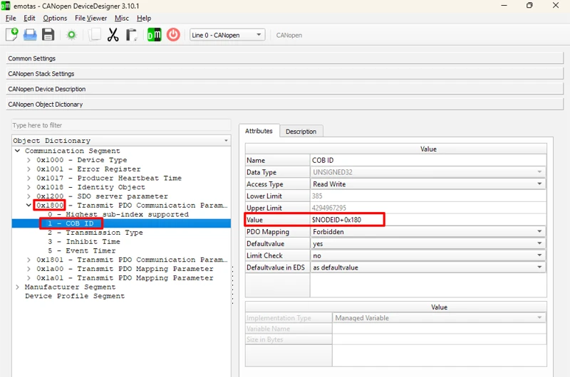
Open index 0x1800. The COB-ID must be the node ID + 0x180, which gives 0x181 for our node. If you see a value such as 0x80000180, the most significant bit is set, and this bit disables the TPDO. In that case, change the value to 0x180 + the node ID to enable the TPDO.
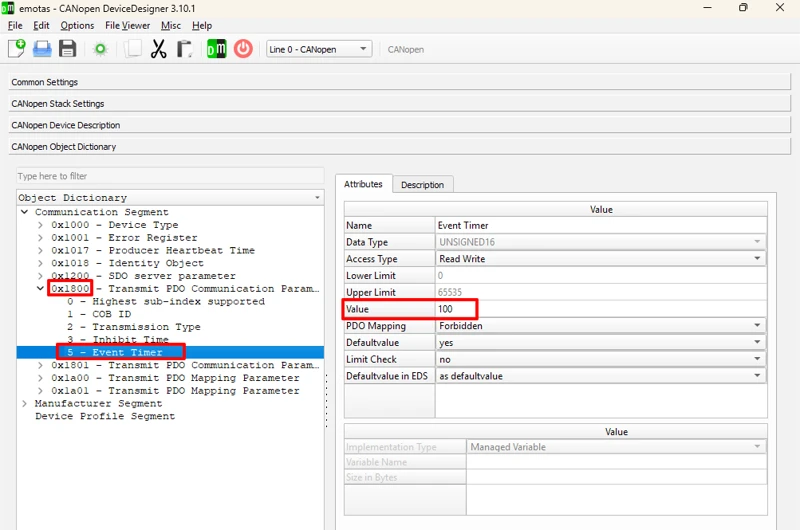
The transmission type is already 254, so it stays unchanged. This TPDO should send data periodically, so we leave the inhibit time unused and set the event timer to 100. The event timer is counted in milliseconds, which makes the node transmit TPDO 1 every 100 milliseconds.
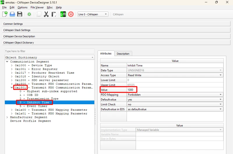
At index 0x1801, the COB-ID is 0x281, and the transmission type, the inhibit time and the event timer all stay at their defaults. The inhibit time is the minimum time that must pass before the same TPDO can be sent again, and it is counted in units of 100 microseconds. A value of 1000 gives a delay of 100 milliseconds, which is useful when a variable changes very fast.
Map Objects into the TPDOs
Double click on 0x2009 under the mask section of the index 0x1A00, which adds one mapping entry for this index.
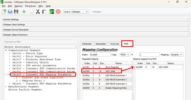
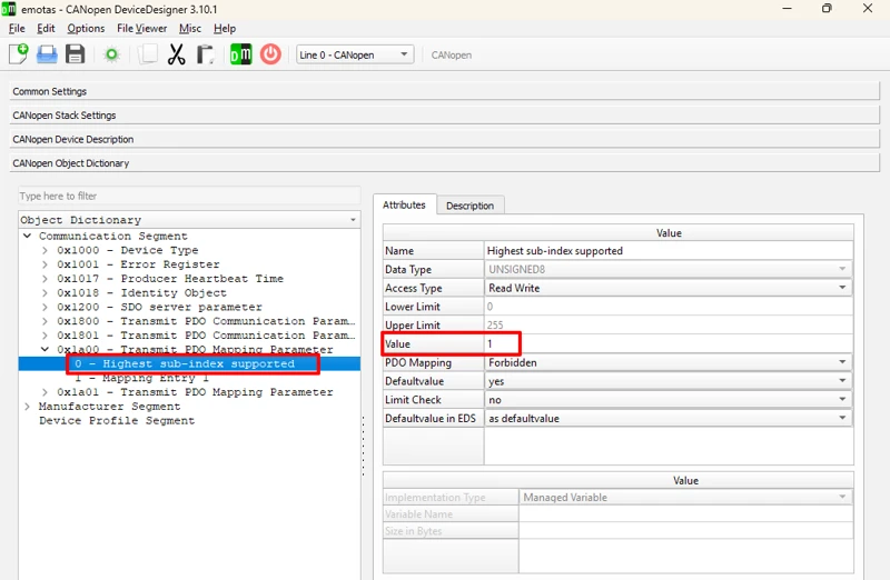
Set the access type to read only and make sure the highest supported subindex shows 1, since there is only 1 mapping entry under this index.
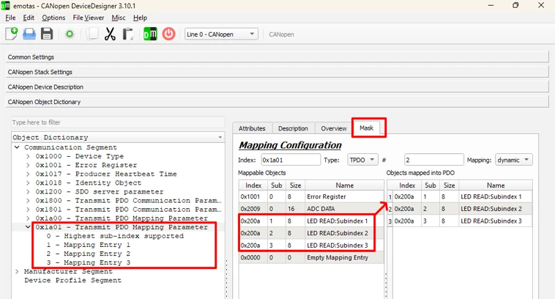
For 0x1A01, add the three subindexes of 0x200A, set the access type to read only, and make sure the highest supported subindex shows 3. Then save the project and click Generate.
Update gen_define.h for TPDO
We created two more objects than in the previous part, so the object counts in gen_define.h will increase by two. The TPDO indexes belong to the default library, so they are already part of the existing count.
#define CO_OBJECTS_LINE_0_CNT	36+2+2u
#define CO_OBJECT_COUNTS 36+2+2uUpdate gen_objdict.c for TPDO
The gen_objdict.c file needs the most changes. As in the previous part, the values in the generated file are correct only for the generated project, so we must correct each lookup value for our own arrays.
Counts and Constants
The object assignment count increases by two, and the description count increases by five. One new descriptor belongs to 0x2009, and the other four belong to 0x200A, which has subindex 0 and the three LED subindexes.
#define CO_OD_ASSIGN_CNT 36+2+2u
#define CO_OBJ_DESC_CNT 148+5+5uThe 8-bit constant array needs no change, because the three values that we need are already present. These values are the contents of the subindex 0 entries, which store a count and not a real data value. The value 3 is needed for subindex 0 of 0x200A, because the array has three LED entries, and also for subindex 0 of 0x1A01, because that TPDO maps three objects. The value 5 is needed for subindex 0 of 0x1800 and 0x1801, because it is the highest supported subindex of a TPDO communication parameter, which includes the unused subindex 4. The value 1 is needed for subindex 0 of 0x1A00, because TPDO 1 maps only the ADC value. Subindex 0 of 0x2009 needs no constant, because that object is a single variable.
/* NO CHANGE IN THIS ARRAY */
static CO_CONST UNSIGNED8 CO_CONST_STORAGE_CLASS	od_const_u8[7+1] = {
	(UNSIGNED8)0u,  //0
	(UNSIGNED8)3u,  // 1
	(UNSIGNED8)4u,
	(UNSIGNED8)2u,
	(UNSIGNED8)5u,  // 4
	(UNSIGNED8)254u,
	(UNSIGNED8)6u,  // 6
(UNSIGNED8)1u}; // 7The 16-bit constant array needs the event timer value 100, which we add at the end. The inhibit time value 1000 is already at position 1.
static CO_CONST UNSIGNED16 CO_CONST_STORAGE_CLASS	od_const_u16[2+1] = {
	(UNSIGNED16)0u,
	(UNSIGNED16)1000u,  // 1
(UNSIGNED16)100u}; // 2The 32-bit constant array needs six new values. In the generated file, the COB-IDs of the two TPDOs are stored as 384 (0x180) and 640 (0x280), and the library adds the node ID to them. We also add the four mapping entries, where each entry holds the index, the subindex and the length in bits of one mapped object. The new values take the positions 27 to 32, and the array count increases by six.
	(UNSIGNED32)384UL,        // 27, COB-ID base of TPDO 1
	(UNSIGNED32)640UL,        // 28, COB-ID base of TPDO 2
	(UNSIGNED32)537460752UL,  // 29, 0x20090010, adcValue
	(UNSIGNED32)537526536UL,  // 30, 0x200A0108, led1Read
	(UNSIGNED32)537526792UL,  // 31, 0x200A0208, led2Read
(UNSIGNED32)537527048UL}; // 32, 0x200A0308, led3ReadApplication Variables
Declare the four new variables as extern in the same file, and extend the pointer arrays that hold their addresses. The LED variables take the positions 4, 5 and 6 of the 8-bit pointer array, because the first four positions are already used by the variables from the previous part. The ADC variable needs a new 16-bit pointer array.
extern uint16_t adcValue;
extern uint8_t led1Read;
extern uint8_t led2Read;
extern uint8_t led3Read;

static UNSIGNED8 CO_CONST_STORAGE_CLASS * CO_CONST 	od_ptr_u8[4+3] = {
	&(my_variable), &(led1), &(led2), &(led3),
	&(led1Read) /* 0x200a:1 */,
	&(led2Read) /* 0x200a:2 */,
	&(led3Read) /* 0x200a:3 */};

static UNSIGNED16 CO_CONST_STORAGE_CLASS * CO_CONST 	od_ptr_u16[1] = {
&(adcValue) /* 0x2009:0 */};The od_data_variables structure must also refer to the new 16-bit array, so add &od_ptr_u16[0] right after the entry for od_ptr_u8. If this entry is missing, the compiler can warn that the array is declared but not used.
CO_CONST CO_OD_DATA_VARIABLES_T od_data_variables = {
   &od_const_u8[0]
    , &od_const_u16[0]
  /* Other Enteries */
#endif /* CO_EXTENDED_DATA_TYPES */
    , &od_const_i8[0]
    , &od_const_i16[0]
    , &od_const_i32[0]
    , &od_i8[0]
    , &od_i16[0]
    , &od_i32[0]
    , &od_ptr_u8[0]
    , &od_ptr_u16[0]  --> /* ADD THIS */
    , NULL
#ifdef CO_EXTENDED_DATA_TYPES
/* Other Enteries */
};Communication Parameters
Every lookup value in a descriptor is a position inside one of the constant arrays. The table below lists the corrected values for the two TPDO communication parameters, where the generated file used the values 6 and 19 for subindexes 0 and 1 of 0x1800. The unchanged entries, such as the transmission type, already point to the value 254.
| Descriptor | New Value | Points To |
|---|---|---|
0x1800:0 | 4 | Position 4 of the 8-bit array, which holds 5 |
0x1800:1 | 27 | Position 27 of the 32-bit array, which holds 384 |
0x1800:5 | 2 | Position 2 of the 16-bit array, which holds 100 |
0x1801:0 | 4 | Position 4 of the 8-bit array, which holds 5 |
0x1801:1 | 28 | Position 28 of the 32-bit array, which holds 640 |
0x1801:3 | 1 | Position 1 of the 16-bit array, which holds 1000 |
CO_CONST CO_OBJECT_DESC_T CO_CONST_STORAGE_CLASS od_description[CO_OBJ_DESC_CNT] = {
  /* Other Enteries */
  { (UNSIGNED8)0u, CO_DTYPE_U8_CONST , (UNSIGNED16)6u, CO_ATTR_NUM | CO_ATTR_READ | CO_ATTR_DEFVAL,  (UNSIGNED16)4u},/* 0x1800:0*/
	{ (UNSIGNED8)1u, CO_DTYPE_U32_TPDO , (UNSIGNED16)1u, CO_ATTR_NUM | CO_ATTR_READ | CO_ATTR_WRITE | CO_ATTR_DEFVAL,  (UNSIGNED16)27u},/* 0x1800:1*/
	{ (UNSIGNED8)2u, CO_DTYPE_U8_TPDO  , (UNSIGNED16)1u, CO_ATTR_NUM | CO_ATTR_READ | CO_ATTR_WRITE | CO_ATTR_DEFVAL,  (UNSIGNED16)5u},/* 0x1800:2*/
	{ (UNSIGNED8)3u, CO_DTYPE_U16_TPDO , (UNSIGNED16)1u, CO_ATTR_NUM | CO_ATTR_READ | CO_ATTR_WRITE | CO_ATTR_DEFVAL,  (UNSIGNED16)0u},/* 0x1800:3*/
	{ (UNSIGNED8)5u, CO_DTYPE_U16_TPDO , (UNSIGNED16)1u, CO_ATTR_NUM | CO_ATTR_READ | CO_ATTR_WRITE | CO_ATTR_DEFVAL,  (UNSIGNED16)2u},/* 0x1800:5*/
	{ (UNSIGNED8)6u, CO_DTYPE_U8_TPDO  , (UNSIGNED16)1u, CO_ATTR_NUM | CO_ATTR_READ | CO_ATTR_WRITE | CO_ATTR_DEFVAL,  (UNSIGNED16)0u},/* 0x1800:6*/
	{ (UNSIGNED8)0u, CO_DTYPE_U8_CONST , (UNSIGNED16)6u, CO_ATTR_NUM | CO_ATTR_READ | CO_ATTR_DEFVAL,  (UNSIGNED16)4u},/* 0x1801:0*/
	{ (UNSIGNED8)1u, CO_DTYPE_U32_TPDO , (UNSIGNED16)2u, CO_ATTR_NUM | CO_ATTR_READ | CO_ATTR_WRITE | CO_ATTR_DEFVAL,  (UNSIGNED16)28u},/* 0x1801:1*/
	{ (UNSIGNED8)2u, CO_DTYPE_U8_TPDO  , (UNSIGNED16)2u, CO_ATTR_NUM | CO_ATTR_READ | CO_ATTR_WRITE | CO_ATTR_DEFVAL,  (UNSIGNED16)5u},/* 0x1801:2*/
	{ (UNSIGNED8)3u, CO_DTYPE_U16_TPDO , (UNSIGNED16)2u, CO_ATTR_NUM | CO_ATTR_READ | CO_ATTR_WRITE | CO_ATTR_DEFVAL,  (UNSIGNED16)1u},/* 0x1801:3*/
	{ (UNSIGNED8)5u, CO_DTYPE_U16_TPDO , (UNSIGNED16)2u, CO_ATTR_NUM | CO_ATTR_READ | CO_ATTR_WRITE | CO_ATTR_DEFVAL,  (UNSIGNED16)0u},/* 0x1801:5*/
	{ (UNSIGNED8)6u, CO_DTYPE_U8_TPDO  , (UNSIGNED16)2u, CO_ATTR_NUM | CO_ATTR_READ | CO_ATTR_WRITE | CO_ATTR_DEFVAL,  (UNSIGNED16)0u},/* 0x1801:6*/
		/* Other Enteries */
};Mapping Parameters
The mapping parameters follow the same rule. Subindex 0 of 0x1A00 must hold the value 1, which sits at position 7 of the 8-bit array, and subindex 0 of 0x1A01 must hold the value 3, which sits at position 1. The mapping entries then point to the four new 32-bit values, where 0x1A00:1 uses position 29 and 0x1A01:1 to 0x1A01:3 use the positions 30, 31 and 32.
CO_CONST CO_OBJECT_DESC_T CO_CONST_STORAGE_CLASS od_description[CO_OBJ_DESC_CNT] = {
  /* Other Enteries */
	{ (UNSIGNED8)0u, CO_DTYPE_U8_TMAP  , (UNSIGNED16)1u, CO_ATTR_NUM | CO_ATTR_READ | CO_ATTR_WRITE | CO_ATTR_DEFVAL,  (UNSIGNED16)7u},/* 0x1a00:0*/
	{ (UNSIGNED8)1u, CO_DTYPE_U32_TMAP , (UNSIGNED16)1u, CO_ATTR_NUM | CO_ATTR_READ | CO_ATTR_WRITE | CO_ATTR_DEFVAL,  (UNSIGNED16)29u},/* 0x1a00:1*/

	{ (UNSIGNED8)0u, CO_DTYPE_U8_TMAP  , (UNSIGNED16)2u, CO_ATTR_NUM | CO_ATTR_READ | CO_ATTR_WRITE | CO_ATTR_DEFVAL,  (UNSIGNED16)1u},/* 0x1a01:0*/
	{ (UNSIGNED8)1u, CO_DTYPE_U32_TMAP , (UNSIGNED16)2u, CO_ATTR_NUM | CO_ATTR_READ | CO_ATTR_WRITE | CO_ATTR_DEFVAL,  (UNSIGNED16)30u},/* 0x1a01:1*/
	{ (UNSIGNED8)2u, CO_DTYPE_U32_TMAP , (UNSIGNED16)2u, CO_ATTR_NUM | CO_ATTR_READ | CO_ATTR_WRITE | CO_ATTR_DEFVAL,  (UNSIGNED16)31u},/* 0x1a01:2*/
	{ (UNSIGNED8)3u, CO_DTYPE_U32_TMAP , (UNSIGNED16)2u, CO_ATTR_NUM | CO_ATTR_READ | CO_ATTR_WRITE | CO_ATTR_DEFVAL,  (UNSIGNED16)32u},/* 0x1a01:3*/
	/* Other Enteries */
};Descriptions and Assignment
Copy the descriptors of 0x2009 and 0x200A from the generated file to the end of our od_description array. The descriptor of 0x2009 needs no change, because it has no constant value. In subindex 0 of 0x200A, change the lookup value from 6 to 1, so it points to the value 3 and not to the value 6. The three LED descriptors use the pointer positions 0, 1 and 2 in the generated file, and we change them to 4, 5 and 6 to match our 8-bit pointer array.
CO_CONST CO_OBJECT_DESC_T CO_CONST_STORAGE_CLASS od_description[CO_OBJ_DESC_CNT] = {
  /* Other Enteries */
	{ (UNSIGNED8)0u, CO_DTYPE_U16_PTR  , (UNSIGNED16)0u, CO_ATTR_NUM | CO_ATTR_READ | CO_ATTR_MAP_TR | CO_ATTR_DEFVAL,  (UNSIGNED16)0u},/* 0x2009:0*/
	{ (UNSIGNED8)0u, CO_DTYPE_U8_CONST , (UNSIGNED16)6u, CO_ATTR_NUM | CO_ATTR_READ | CO_ATTR_DEFVAL,  (UNSIGNED16)1u},/* 0x200a:0*/
	{ (UNSIGNED8)1u, CO_DTYPE_U8_PTR   , (UNSIGNED16)4u, CO_ATTR_NUM | CO_ATTR_READ | CO_ATTR_MAP_TR | CO_ATTR_DEFVAL,  (UNSIGNED16)0u},/* 0x200a:1*/
	{ (UNSIGNED8)2u, CO_DTYPE_U8_PTR   , (UNSIGNED16)5u, CO_ATTR_NUM | CO_ATTR_READ | CO_ATTR_MAP_TR | CO_ATTR_DEFVAL,  (UNSIGNED16)0u},/* 0x200a:2*/
	{ (UNSIGNED8)3u, CO_DTYPE_U8_PTR   , (UNSIGNED16)6u, CO_ATTR_NUM | CO_ATTR_READ | CO_ATTR_MAP_TR | CO_ATTR_DEFVAL,  (UNSIGNED16)0u},/* 0x200a:3*/
};Next, copy the two new entries into the od_assign array. The last value of each entry is the position where the descriptors of that object start. The last existing object, 0x2008, starts at 149 and has four descriptors, so 0x2009 starts at 153 and 0x200A starts at 154.
CO_CONST CO_OD_ASSIGN_T CO_CONST_STORAGE_CLASS od_assign[CO_OD_ASSIGN_CNT] = {
  /* Other Enteries */
  { 0x2009u, 1u, 0u, CO_ODTYPE_VAR, 153u },
  { 0x200au, 4u, 3u, CO_ODTYPE_ARRAY, 154u },
};Update gen_indices.h
Open the generated gen_indices.h, copy the new entries for 0x2009 and 0x200A, and paste them into the same file in our project. The names come from the labels that we typed in the Device Designer.
#define I_ADC_DATA               	0x2009u
#define I_LED_READ               	0x200au
#define  S_SUBINDEX_1             	0x1u
#define  S_SUBINDEX_2             	0x2u
#define  S_SUBINDEX_3             	0x3u
#define S_NUMBER_OF_ENTRIES 0x0uSTM32 TPDO Application Code
Define the Variables and Read the LEDs
Define the four variables in main.c, using exactly the same names as in the object dictionary.
uint16_t adcValue;
uint8_t led1Read;
uint8_t led2Read;
uint8_t led3Read;In the main loop, we read the state of the three LED pins with HAL_GPIO_ReadPin and store the results in the ledRead variables. The stack sends the current values of these variables whenever it transmits TPDO 2.
Read the ADC
The function adcUpdate reads the potentiometer in polling mode. It starts the conversion, waits until the conversion is complete, reads the result into adcValue, and then stops the ADC. We call it in the main loop, so the value stays up to date for TPDO 1.
void adcUpdate (void)
{
	HAL_ADC_Start(&hadc1);
	HAL_ADC_PollForConversion(&hadc1, 50);
	adcValue = HAL_ADC_GetValue(&hadc1);
	HAL_ADC_Stop(&hadc1);
}Send TPDO 2 on Change
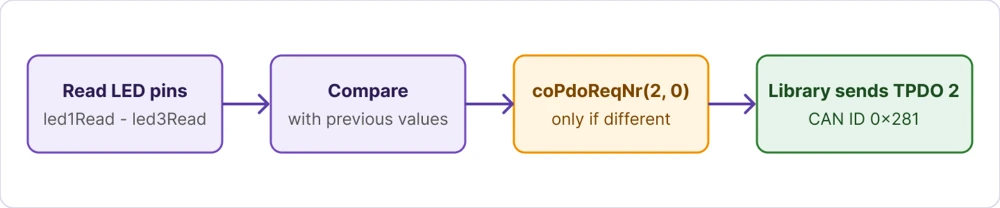
When I first tested this project, TPDO 2 did not send any message, even though the LED states changed. The library cannot detect a change in a plain variable, because our own code updates the variable directly. For this reason, we must detect the change ourselves. The function my_pdo_update_callback compares the three ledRead variables with the values that it stored the last time. If any value is different, it stores the new values and calls coPdoReqNr, which requests the transmission of the TPDO. We are not sending the values ourselves, because the library reads the mapped objects and builds the frame. The parameter is the TPDO number, which is 2 in our case.
void my_pdo_update_callback(UNSIGNED16 pdoNr)
{
	static UNSIGNED8 prev_ledRead1 = 0;
	static UNSIGNED8 prev_ledRead2 = 0;
	static UNSIGNED8 prev_ledRead3 = 0;

	if ((led1Read != prev_ledRead1) || (led2Read != prev_ledRead2) || (led3Read != prev_ledRead3))
	{
		prev_ledRead1 = led1Read;
		prev_ledRead2 = led2Read;
		prev_ledRead3 = led3Read;

		coPdoReqNr(pdoNr, 0);
	}
}This function needs the declaration of coPdoReqNr, so include gen_define.h and co_canopen.h at the top of main.c. The diagram below shows the order of the steps.
Update the Main Loop
All the application code runs inside the main loop, and only when the node is in the operational state and the CAN bus is on. We call my_pdo_update_callback after the ledRead variables are updated, so the comparison always uses the latest pin states.
if ((nmtState == CO_NMT_STATE_OPERATIONAL) && (CANState == CO_CAN_STATE_BUS_ON))
{
	Application_Process();
	HAL_GPIO_WritePin(GPIOA, GPIO_PIN_1, led1);
	HAL_GPIO_WritePin(GPIOA, GPIO_PIN_2, led2);
	HAL_GPIO_WritePin(GPIOA, GPIO_PIN_3, led3);
	led1Read = HAL_GPIO_ReadPin(GPIOA, GPIO_PIN_1);
	led2Read = HAL_GPIO_ReadPin(GPIOA, GPIO_PIN_2);
	led3Read = HAL_GPIO_ReadPin(GPIOA, GPIO_PIN_3);
	my_pdo_update_callback(2);
	adcUpdate();
}Test TPDO with TSMaster
In TSMaster, I have added three commands. The NMT command puts the node into the operational mode, which is always the first step, because PDOs and our application do not run in the pre-operational mode. The two RPDO write commands use the CAN ID 0x201 with one data byte for 0x1600, and the CAN ID 0x301 with three data bytes, one for each LED, for 0x1601.
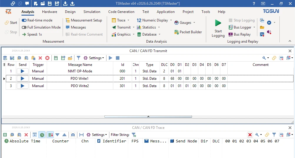
After connecting TSMaster to the CAN bus and putting the node into the operational mode, the TPDO 1 with the CAN ID 0x181 starts to appear every 100 milliseconds.
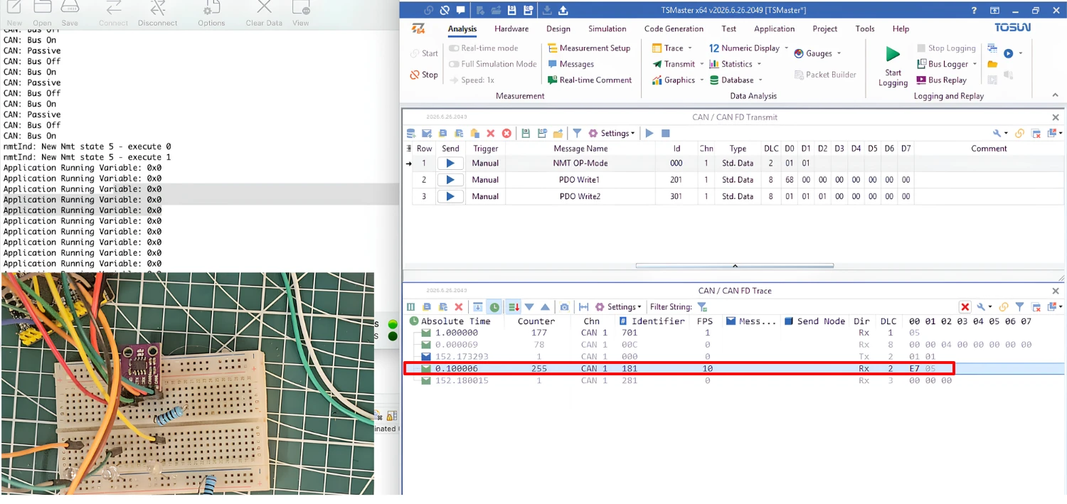
You can see the STM32 Node is sending TPDO 1 (0x181) every 100ms. The data 0x05E7 (E7 05) is the current 12-bit potentiometer value.
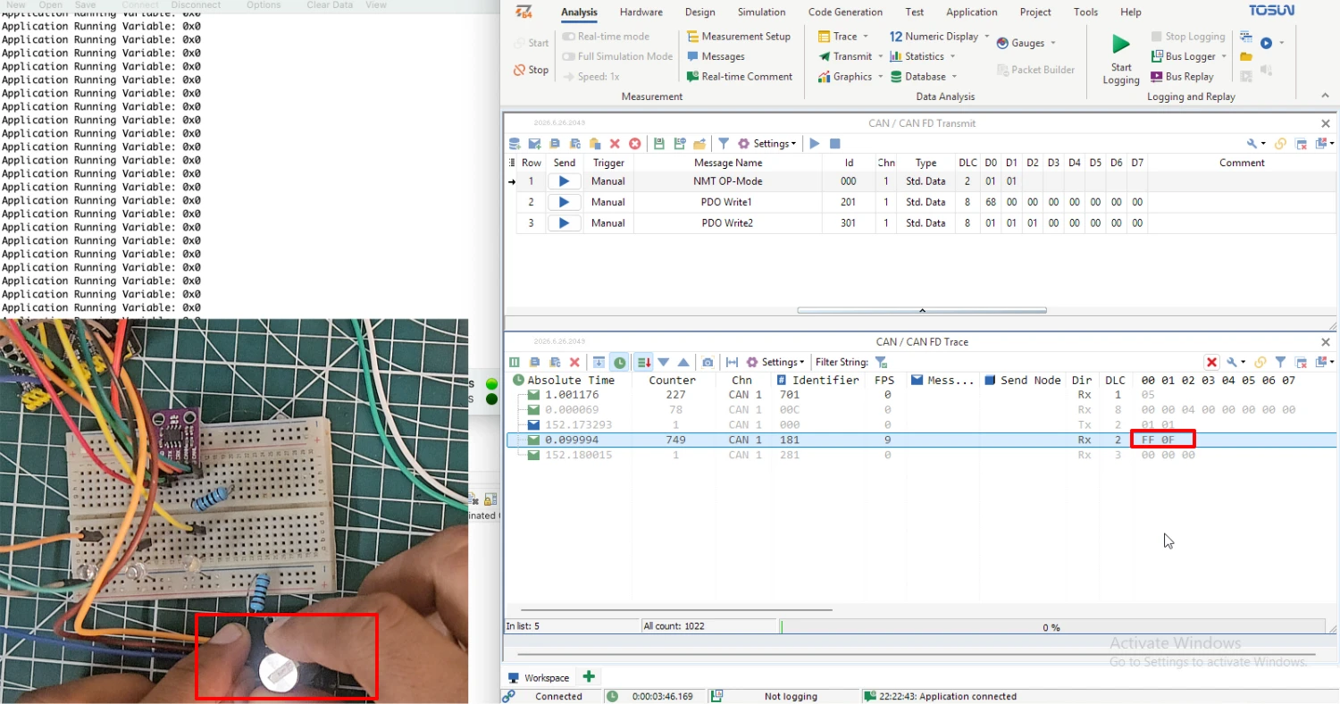
Rotate the potentiometer and watch the data of TPDO 1 change. At the highest position, the 12-bit value reaches 0xFFF (0xFF 0x0F), which is 4095 in decimal. The ADC value is sent with the least significant byte first, so the value 0xFFF appears as the bytes FF 0F. This is why the first byte fluctuates more than the second byte while you rotate the potentiometer.
Send the RPDO command from the previous part to turn the LEDs on or off. The LEDs respond, and TPDO 2 (0x281) sends a new frame that carries the new LED states each time they change.
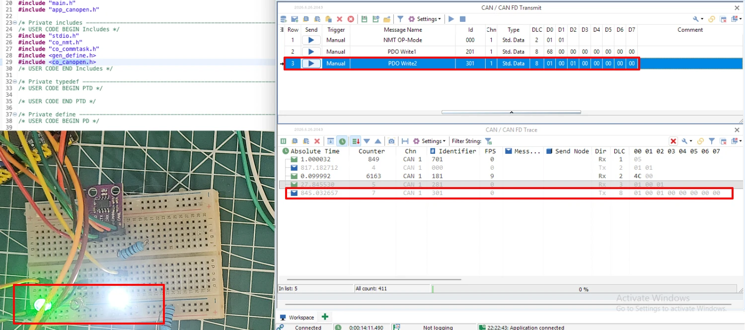
As the image above shows, TSMaster transmitted the data 1 0 1 and the LEDs turned on and off in the same order. The STM32 Node transmitted TPDO 2 with the updated LED states. TPDO 2 transmites only when the LED states change, which shows that our callback and the library work together correctly.
Conclusion
In this part, we configured the STM32 node to transmit data to the CANopen master using the TPDO protocol. We created two TPDOs in the Device Designer, mapped the ADC object and the three LED objects into them, and updated the generated files for our project.
TPDO 1 sends the potentiometer value every 100 milliseconds through the event timer. TPDO 2 sends the LED states only when they change. Because the library does not detect changes in plain variables, we added our own function that compares the values and requests the transmission with coPdoReqNr.
With this part, the PDO communication of the series is complete. The STM32 node now receives data with the RPDO protocol and transmits data with the TPDO protocol. In the next part, we will cover the Heartbeat and Emergency messages, and see how the master checks whether a node is alive and how the node reports application faults.
Download Project Here
Download the CubeMX project files and HAL source code — all tested on real hardware.
If you find this useful, you can support us with a Donation as well.
Browse More STM32 CANopen Tutorials

Subscribe
Login
0 Comments
Newest

