
Home ▸ Uncategorized ▸
Updated On: September 22, 2026
STM32 Modbus TCP Client using LWIP – Part 7: Reading Registers and Coils
This is Part 7 in the STM32 Modbus TCP series using the LwIP Ethernet library. In Part 6, we configured the STM32 as a Modbus TCP client. We set up Ethernet in CubeMX, built the client project, and sent a test request to the server just to confirm that the connection was working. The server received that request and decoded it correctly, which confirmed that the client is configured correctly.
Today, we will continue building on top of the previous project. We are going to add the ability to actually read data from the server, including holding registers, input registers, coils and discrete inputs. On the server side, I have already set up a small database for each of these. Our STM32 client will read this data over TCP and print it on the serial console. We will also see what happens when the client asks for data that is not available on the server.
STM32 Modbus TCP Client using LWIP — Video Tutorial (Part 7)
This video shows how to extend the STM32 Modbus TCP client to read holding registers, input registers, coils, and discrete inputs. We build the request and parser functions, trigger each read using a push button on the Nucleo board, and test the client against a Python-based Modbus server, including how it handles exception responses.
How the STM32 Modbus Client Reads Registers and Coils
I am continuing from the same project we left off in Part 6. Inside the Modbus folder, where we keep all our Modbus related source files, we are adding a few new files today. The Modbus_Client_Parser files are being updated, since we now need to decode the actual data coming back from the server. Alongside these, there are two new files for building the requests, Modbus_Client_Request.c and Modbus_Client_Request.h.
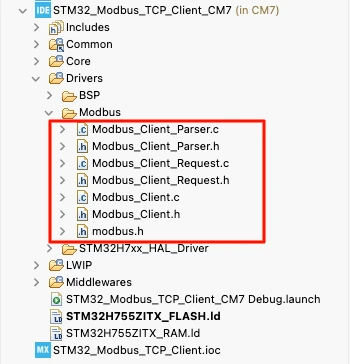
If you are copying these files into your own project, remember to overwrite the existing parser files, since they already exist from Part 6.
Here’s what each of these files does:
- Modbus_Client_Request.c — builds the request frame for each of the four read function codes, and stores the address we requested so the parser can use it later.
- Modbus_Client_Parser.c — decodes the response for each function code, stores the values in the right buffer, and prints them on the serial console.
- main.c — reads a push button on the Nucleo board and uses it to trigger a different read request on every press.
Modbus Client Request Files Explained
Let us start with Modbus_Client_Request.c. This file contains four functions, one for each function code we are implementing today: MB_ReadHoldingRegisters, MB_ReadInputRegisters, MB_ReadCoils, and MB_ReadDiscreteInputs. All four follow the same pattern, so understanding one is enough to understand the rest.
MB_ReadHoldingRegisters
This function takes four parameters. The first is the transaction ID, which we set at runtime. Next is the unit ID, which is the ID of the slave, meaning the server. Then comes the start address, from where we want to begin reading, and finally the quantity, which tells the server how many registers we want.
err_t MB_ReadHoldingRegisters(uint16_t txnID, uint8_t unitID, uint16_t addr, uint16_t qty)
{
	MB_CurrentRequest.StartAddress = addr;
	MB_CurrentRequest.Quantity = qty;

    uint8_t tx[12];
    /* MBAP Header */
    tx[0]=txnID>>8;
    tx[1]=txnID++;

    tx[2]=0;
    tx[3]=0;

    tx[4]=0;
    tx[5]=6;

    tx[6]=unitID;

    /* PDU */
    tx[7]=MB_FC_READ_HOLDING_REGS;

    tx[8]=addr>>8;
    tx[9]=addr;

    tx[10]=qty>>8;
    tx[11]=qty;

    return TCP_SendRequest(tx, 12);
}Before building the request frame, notice the first two lines. We save the start address and the quantity inside the MB_CurrentRequest structure. This matters because the server does not send the start address back in its response. It only sends the byte count followed by the data. Since the parser needs to know where this data belongs, we keep track of the start address ourselves, and this structure is exactly where we store it.
The request is made up of two parts, the MBAP header and the PDU. The MBAP header consists of the following:
- Two bytes for the transaction ID
- Two bytes for the protocol ID, which is always 0 for Modbus TCP
- Two bytes for the length field, which stays fixed at 6 for a read request
- One byte for the unit ID.

The PDU consists of:
- One byte for the function code, already defined for us in
modbus.h - Two bytes for the start address, from where we want to read the data
- Two bytes for the quantity representing how many registers/coils we want to read
In total, the request comes out to 12 bytes, which is exactly what we send to the server using TCP_SendRequest, the same function we built back in Part 6.
The remaining three functions, MB_ReadInputRegisters, MB_ReadCoils, and MB_ReadDiscreteInputs, build their frame in exactly the same way. The only thing that changes between them is the function code placed at index 7, which comes from modbus.h.
Parsing the Modbus Server Response
When the server sends data back, the tcp_client_recv callback inside the Modbus_Client.c will be called. We have already covered this callback in the previous tutorial, where it copies the data into rxBuf, and then calls MB_Client_Parser. In Part 6, this function only printed the number of bytes received. But now, it actually decodes the response.
err_t MB_Client_Parser(struct tcp_pcb *pcb, uint8_t *rx, uint16_t len)
{
    if(len < 9)
        return ERR_VAL;

    uint8_t FunctionCode = rx[7];

    /* Exception Response */
    if(FunctionCode & 0x80)
        return MB_ParseException(rx);

    switch(FunctionCode)
    {
        case MB_FC_READ_HOLDING_REGS:
            return MB_ParseReadHoldingRegisters(rx);

        case MB_FC_READ_INPUT_REGS:
            return MB_ParseReadInputRegisters(rx);

        case MB_FC_READ_COILS:
            return MB_ParseReadCoils(rx);

        case MB_FC_READ_DISCRETE_INPUTS:
            return MB_ParseReadDiscreteInputs(rx);

        default:
            printf("Unsupported Function Code : %d\r\n", FunctionCode);
            break;
    }

    return ERR_OK;
}The first check makes sure the received data is at least 9 bytes long. This is because the MBAP header alone is 7 bytes, and a valid PDU needs at least 2 more bytes. So anything shorter than that means the response is incomplete and cannot be decoded.

Next, we read the function code from index 7 of the buffer and then check whether the most significant bit of this byte is set. Whenever the server rejects a request, it sends back an exception response, and it marks this by setting the MSB of the function code. If this bit is set, we pass the buffer to MB_ParseException for handling the exception code. Otherwise, we call the parser function that matches the function code in the response.
Reading Holding Registers
The function MB_ParseReadHoldingRegisters is used to handle the response received for Function Code 0x03, that is, foe reading the Holding Registers.
static err_t MB_ParseReadHoldingRegisters(uint8_t *rx)
{
    uint8_t byteCount = rx[8];
    uint16_t quantity = byteCount / 2;
    uint16_t startAddress = MB_CurrentRequest.StartAddress;

    for(uint16_t i = 0; i < quantity; i++)
    {
        HoldingRegBuffer[startAddress + i] = ((uint16_t)rx[9 + 2*i] << 8) | (uint16_t)rx[10 + 2*i];
    }

    for(uint16_t i = 0; i < quantity; i++)
    {
        printf("[%03d] = %u\r\n", startAddress + i, HoldingRegBuffer[startAddress + i]);
    }

    return ERR_OK;
}Here we first read the byte count from index 8 of the buffer. Since every register is 16 bits wide and the server sends two bytes for each one, dividing the byte count by 2 gives us the actual number of registers in this response.
We then fetch the start address that we saved earlier in MB_CurrentRequest structure, and use it to place each incoming register at the correct position inside HoldingRegBuffer.
The two data bytes for every register begin at index 9, and we combine them into a single 16-bit value before storing it.
In order to represent the processing of this data, I am simply printing each register number along with its value on the serial console.
MB_ParseReadInputRegisters works in exactly the same way. The only difference is the function code it responds to, and that the values are stored inside InputRegBuffer.
Reading Coils and Discrete Inputs
Coils and discrete inputs are decoded a little differently, since the server packs one bit per coil instead of two bytes per register.
static err_t MB_ParseReadCoils(uint8_t *rx)
{
    uint8_t byteCount = rx[8];
    uint16_t startAddress = MB_CurrentRequest.StartAddress;

    for(uint8_t i = 0; i < byteCount; i++)
    {
        for(uint8_t bit = 0; bit < 8; bit++)
        {
            CoilBuffer[startAddress + (i * 8) + bit] = (rx[9 + i] >> bit) & 0x01;
        }
    }

    for(uint16_t i = 0; i < (byteCount * 8); i++)
    {
        printf("[%03d] = %d\r\n", startAddress + i, CoilBuffer[startAddress + i]);
    }

    return ERR_OK;
}Here, the byte count tells us how many complete bytes the server sent, and every byte carries the data for 8 coils. Even if we requested only 3 coils, the server still has to send one full byte, since coils cannot be sent as partial bytes.
To extract each individual bit, we use two loops. The outer loop runs once for every byte received, and the inner loop runs eight times inside it, once for every bit in that byte. For each bit, we shift the byte to the right by the bit position and mask it with 0x01, which isolates that single bit as either a 0 or a 1.
This value is then stored in CoilBuffer, at a position calculated from the start address, the byte index, and the bit index.
After storing the data into the buffer, we need to process it. In order to show this processing, I am printing the received data on the serial console. Notice that the loop runs byteCount * 8 times, since we are now printing the result for each coil individually.
MB_ParseReadDiscreteInputs follows the identical logic, only it stores its values inside InputBuffer.
Handling Exception Responses
If the server rejects a request sent by the client, it sends and exception response back to the client. The function MB_ParseException handles this response.
static err_t MB_ParseException(uint8_t *rx)
{
    uint8_t functionCode  = rx[7] & 0x7F;
    uint8_t exceptionCode = rx[8];

    printf("Function Code : %d\r\n", functionCode);
    printf("Exception Code: %d - ", exceptionCode);

    switch(exceptionCode)
    {
        case MB_EX_ILLEGAL_FUNCTION:
            printf("Illegal Function");
            break;

        case MB_EX_ILLEGAL_DATA_ADDRESS:
            printf("Illegal Data Address");
            break;

        case MB_EX_ILLEGAL_DATA_VALUE:
            printf("Illegal Data Value");
            break;

        case MB_EX_SERVER_DEVICE_FAILURE:
            printf("Server Device Failure");
            break;

        default:
            printf("Unknown Exception");
            break;
    }

    return ERR_OK;
}This function simply masks off the MSB to recover the original function code. Then it reads the exception code from index 8 and prints out what kind of exception the server has sent. We will see this in action shortly, when we request data from addresses the server does not have.
Using a Push Button to Trigger Modbus Requests
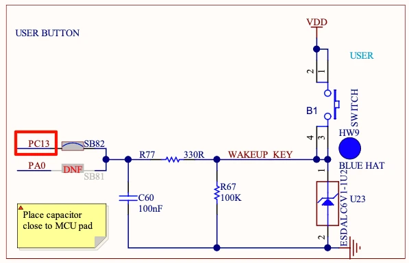
To trigger different requests from the STM32, I am using the user button on the Nucleo H755, which is wired to pin PC13. Every press of this button will call the next function code in sequence.
CubeMX Configuration for the Button
We will configure the pin PC13 as an external Interrupt.
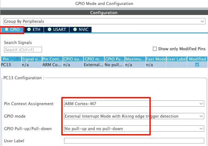
Since this is a dual core board, make sure the pin context assignment is set to Cortex-M7, as our entire application runs on that core. There is no need to configure a pull-up or pull-down here, because the pin is already pulled down on the Nucleo board itself.
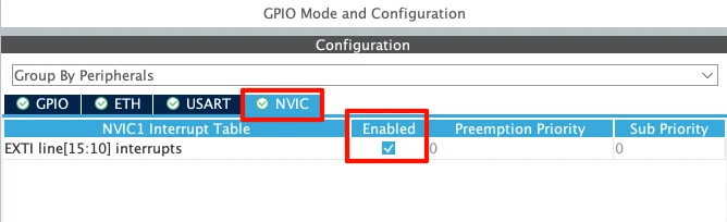
Go to the NVIC tab and enable the interrupt for the EXTI line.
Reading Requests from main.c
Inside main.c, we define a volatile integer called isPressed, which is set to 1 whenever the button is pressed. Also define a counter variable to keep track of how many times the button has been pressed.
int counter = 0;
volatile int isPressed = 0;

void HAL_GPIO_EXTI_Callback(uint16_t GPIO_Pin)
{
	isPressed = 1;
}Inside the main loop, we check whether the button has been pressed. If it has, we reset isPressed back to 0, and increment the counter. Based on the counter value, we call different functions to request registers or coils data from the server.
if (isPressed == 1)
{
	HAL_Delay(200);  // debouncing
	isPressed = 0;
	counter++;

	switch (counter)
	{
	case 1:
		MB_ReadHoldingRegisters(counter, 1, 5, 10);
		break;
	case 2:
		MB_ReadInputRegisters(counter, 1, 7, 3);
		break;
	case 3:
		MB_ReadCoils(counter, 1, 10, 8);
		break;
	case 4:
		MB_ReadDiscreteInputs(counter, 1, 8, 5);
		break;
	default:
		break;
	}

	if (counter >= 4) counter = 0;
}For the transaction ID, I am simply passing the counter value, so it becomes 1 for holding registers, 2 for input registers, 3 for coils, and 4 for discrete inputs.
The unit ID is set to 1, though it does not really matter here since we are only connecting to a single server.
Once the counter reaches 4, it resets back to 0, and the next button press starts the cycle again from holding registers.
Modbus Client Testing – Registers, Coils and Exceptions
For testing, I am again using a small Python script as the Modbus server. This script has a database of 10 holding registers, 10 input registers, 16 coils, and 16 discrete inputs. That means we can request at most 10 registers, or at most 16 coils or discrete inputs, from this server.
HOST = "0.0.0.0"
PORT = 502

COILS = [
    1,0,1,1,0,1,0,0,
    1,1,0,0,1,0,1,0
]

INPUTS = [
    0,1,0,0,1,1,0,1,
    1,0,1,0,0,1,0,1
]

HOLDING_REGS = [
    100,101,102,103,104,
    105,106,107,108,109
]

INPUT_REGS = [
    1000,1001,1002,1003,1004,
    1005,1006,1007,1008,1009
]Reading Holding Registers
We will start with reading Holding Registers. Inside the main function, I am configuring the client to read 16 registers, starting from address 0.
	case 1:
		MB_ReadHoldingRegisters(counter, 1, 0, 16);
break;Below is the image showing the request received by the server and data received by the client.
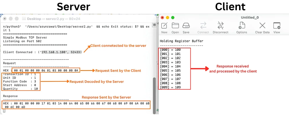
Client has received the data for all 16 registers and it matches to exactly what we have defined in the server’s database. Now I am going to change the start address and quantity.
	case 1:
		MB_ReadHoldingRegisters(counter, 1, 5, 10);
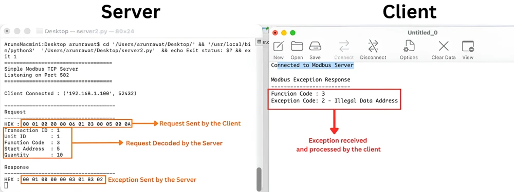
break;The client is now requesting 10 registers, starting from register 5. Basically the client wants to read the registers 5, 6, 7, …. 14. Note that the server only has the data for 10 registers and hence this request will be rejected by the server.
The image below shows the exception sent by the server.
Reading Input Registers
Next, we will read the Input Registers. I am configuring the client to read 10 registers, starting from address 0, the same way we did for holding registers.
	case 2:
		MB_ReadInputRegisters(counter, 1, 0, 10);
break;Below is the image showing the request received by the server and data received by the client.
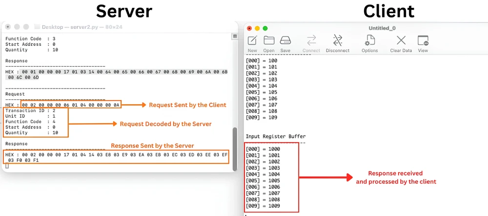
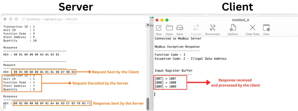
The client has received all 10 input register values, and they match exactly with the server’s database. Now let us change the start address and quantity, and request only 3 registers, starting from address 7.
	case 2:
		MB_ReadInputRegisters(counter, 1, 7, 3);
break;The client is now requesting registers 7, 8, and 9. Since the server’s database goes up to address 9, this request stays within range, and the server responds with the correct data instead of an exception.
The image below shows the data received for this request.
Reading Coils
Now we will read the Coils. I am configuring the client to read 16 coils, starting from address 0, since the server’s database holds 16 coils in total.
	case 3:
		MB_ReadCoils(counter, 1, 0, 16);
break;Below is the image showing the request received by the server and data received by the client.
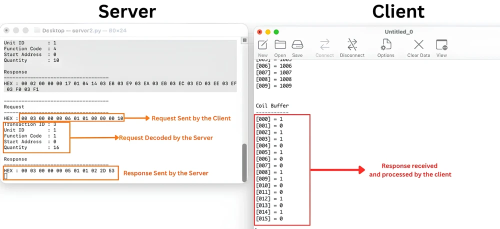
The client has received all 16 coil values, and they match exactly with what is stored on the server. Now let us change the start address and quantity.
	case 3:
		MB_ReadCoils(counter, 1, 10, 8);
break;The client is now requesting 8 coils, starting from coil number 10. This means the client wants coils 10 through 17, but the server only has coils up to number 15. Since this request goes beyond the available range, the server rejects it.
The image below shows the exception sent by the server.
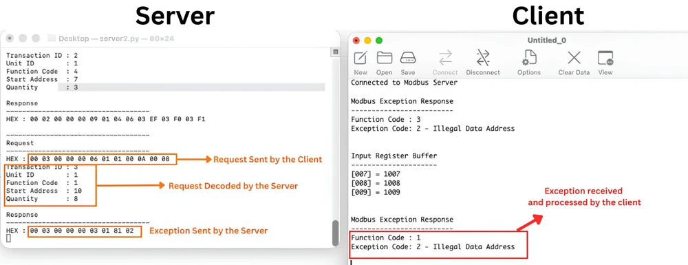
Just like with holding registers, the exception code here is 2, Illegal Data Address, confirming that the requested coils are not available on the server.
Reading Discrete Inputs
Finally, we will read the Discrete Inputs. I am configuring the client to read 16 discrete inputs, starting from address 0.
	case 4:
		MB_ReadDiscreteInputs(counter, 1, 0, 16);
break;Below is the image showing the request received by the server and data received by the client.
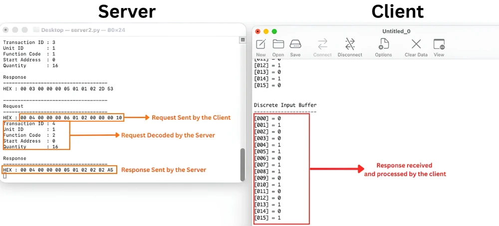
The client has received all 16 values, and they match exactly with the server’s database. Now let us change the start address and quantity.
	case 4:
		MB_ReadDiscreteInputs(counter, 1, 8, 5);
break;The client is now requesting 5 discrete inputs, starting from number 8. Since the server’s database goes up to input 15, this request stays within range, so we should get the data back instead of an exception.
The image below shows the data received for this request.
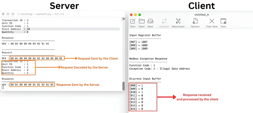
Here, you will notice that the server has sent 8 bits of data instead of 5, even though we only asked for 5 discrete inputs. This happens because the server cannot transmit anything less than a full byte. The first 5 bits carry the actual data for our requested inputs, and the remaining 3 bits are simply padded with zeros to complete the byte.
STM32 Modbus TCP Client – Frequently Asked Questions
Conclusion
With this, the STM32 Modbus TCP client is now able to read holding registers, input registers, coils, and discrete inputs from a server, and decode each of these responses correctly. We also saw how the client handles an exception, whenever the requested address goes beyond what the server has in its database. Along the way, we used a simple button press on the Nucleo board to trigger these requests one at a time, which made it easy to test each function code on its own.
This completes the read side of our Modbus TCP client. In the next part of this series, we will move in the other direction and start writing data to the server, using function codes 5, 6, 15, and 16 to write single and multiple coils and registers.
Download STM32 Modbus TCP Client — Reading Registers and Coils Project
Open source CubeMX project files and HAL source code, tested on real hardware. Free to use — support the work if it helped you.
Browse More STM32 Modbus TCP Tutorials

Subscribe
Login
0 Comments
Newest

