
Home ▸ Uncategorized ▸
Updated On: September 22, 2026
STM32 Modbus TCP Client using LWIP – Part 6: Setting Up the Client
This is Part 6 in the STM32 Modbus TCP series using the LwIP Ethernet library. In the first five parts of this series, we built a complete Modbus TCP server on the STM32, capable of handling every function code needed to read/write coils and registers, along with sending exceptions whenever required.
Starting with this part, we will switch direction. Instead of continue building the server, we will configure the STM32 as a Modbus TCP client. This is the first tutorial in the client half of the series. In this tutorial, we will set up the STM32 Ethernet peripheral and build a basic Modbus TCP client. This client does not process any function code yet. It simply sends a request to the server, so we know the client itself is working. In the upcoming parts of this series, we will keep building on top of this same client project, adding one function code at a time, the same way we did for the server.
This is a new project, so we are configuring Ethernet from scratch. I am using the Nucleo H755 board for this series. The Ethernet configuration itself follows the same steps I used in my Ethernet configuration tutorial, so I will refer to that wherever the steps overlap.
STM32 Modbus TCP Client using LWIP — Video Tutorial (Part 6)
This video walks through configuring the STM32 as a Modbus TCP client using LWIP. We set up Ethernet in CubeMX, prepare the memory layout for the LWIP heap and DMA buffers, build a client project that connects to a Modbus TCP server, and test it against a Python-based server, sending a basic query and confirming the response.
How the STM32 Modbus TCP Client Works
Before we start configuring the project in CubeMX, let’s understand how the pieces fit together. The client is built around three files, and each one has a specific job.
Project Files and Their Role
- modbus.h — holds the function code definitions and the exception codes, the same ones the server side of this series already uses.
- Modbus_Client.c — sets up the TCP client itself. It creates the TCP control block, connects to the server’s IP and port, handles retries, and registers the connected, receive, and error callbacks.
- Modbus_Client_Parser.c — parses whatever bytes come back from the server. For this part, it only reports how many bytes were received, since we are not decoding a response yet.
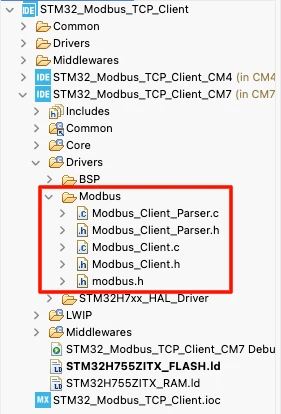
You can get these files after downloading the project from the end of this post. They are placed inside the Project Folder -> CM7 -> Drivers -> Modbus Folder.
Request-Response Flow
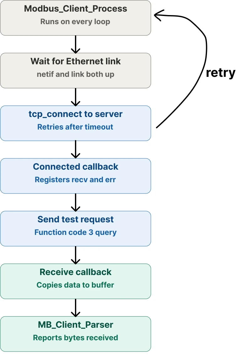
The function Modbus_Client_Process is first called inside the main loop. This function waits for the Ethernet link to come up, and then attempts a connection to the server. If the connection does not succeed, it retries after a short timeout, up to a fixed number of attempts, after which the client stops trying until the board is reset.
Once the client is connected to the server, the connected callback registers the receive and error callbacks. It then sends a test Modbus request, just to confirm the server on the other end receives and decodes it correctly.
From there, every time the server sends data back, the receive callback runs. It copies the data into our own buffer and passes it to the parser. Since we are not decoding any function code responses in today’s tutorial, the parser simply reports how many bytes were received.
The image below shows how a request moves through these callbacks, from the TCP connect stage to the test request being sent out.
STM32CubeMX Configuration for Modbus TCP
The Ethernet setup for this series follows the same pattern I used for the H745 Discovery board in my Ethernet configuration tutorial.
Clock Configuration
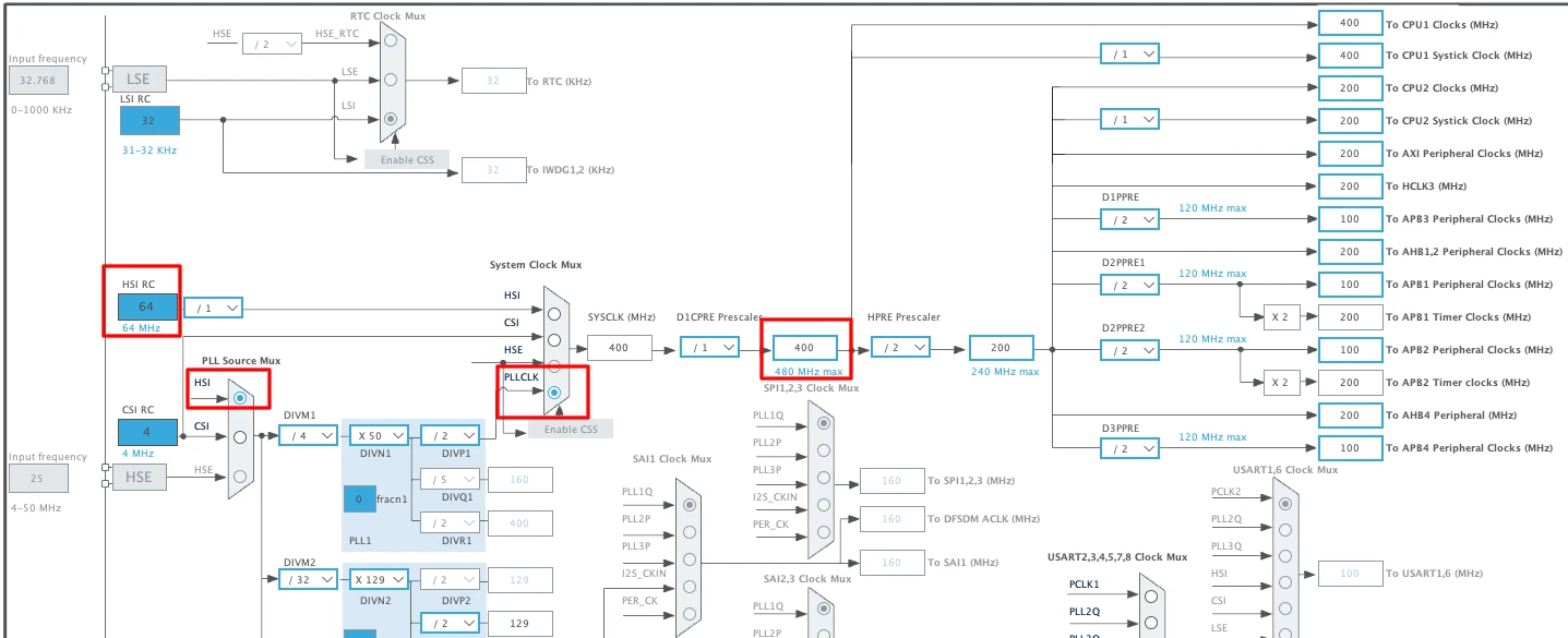
I am using the internal HSI oscillator at 64 MHz to provide the clock. Using the PLL, we will run the system at a clock of 400 MHz.
Ethernet Configuration
Go to Connectivity -> Ethernet and set the mode to RMII. Nulceo H755 uses the RMII type connection as shown in the image from the schematics below.
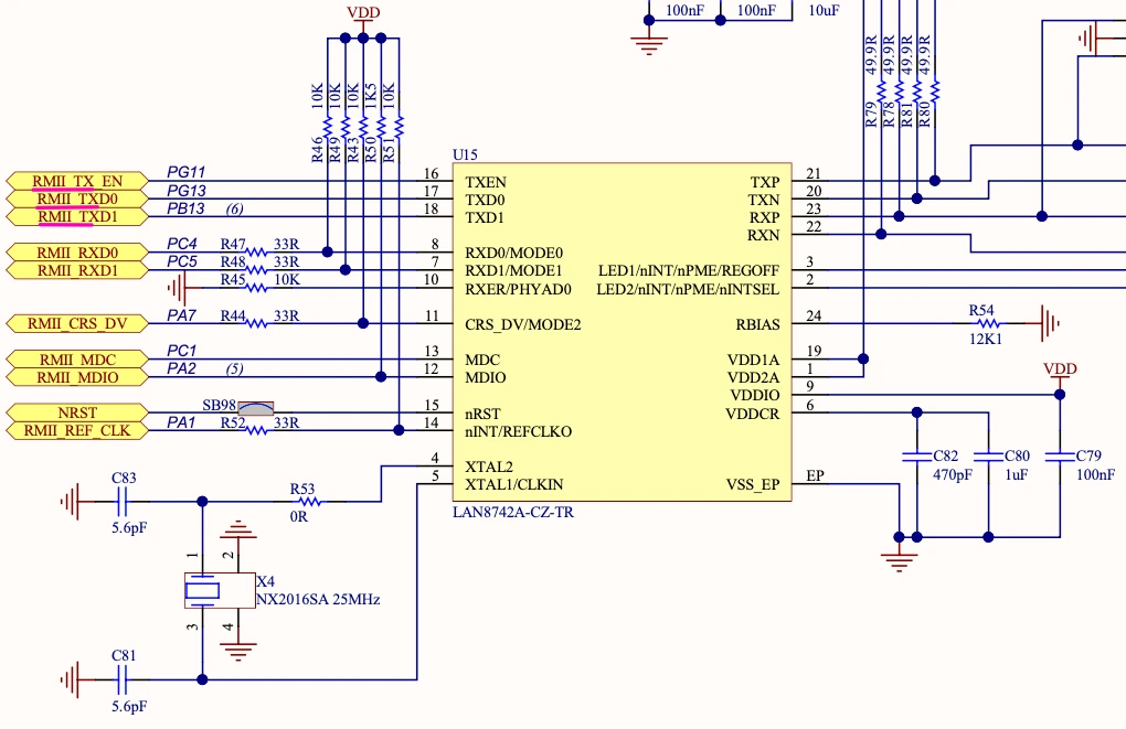
CubeMX sometimes auto-assigns the wrong pins for Ethernet, so compare every pin against the schematic before moving on.
Open the Ethernet parameters and check the memory layout.
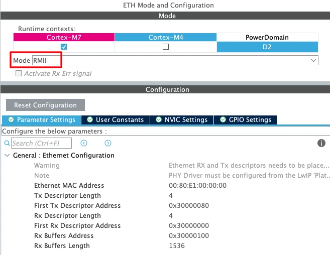
This is the same layout I explained in the Ethernet configuration tutorial:
- RX DMA descriptors start at
0x30000000 - TX DMA descriptors start at
0x30000080 - RX buffers start at
0x30000100 - Each RX buffer is 1536 bytes.
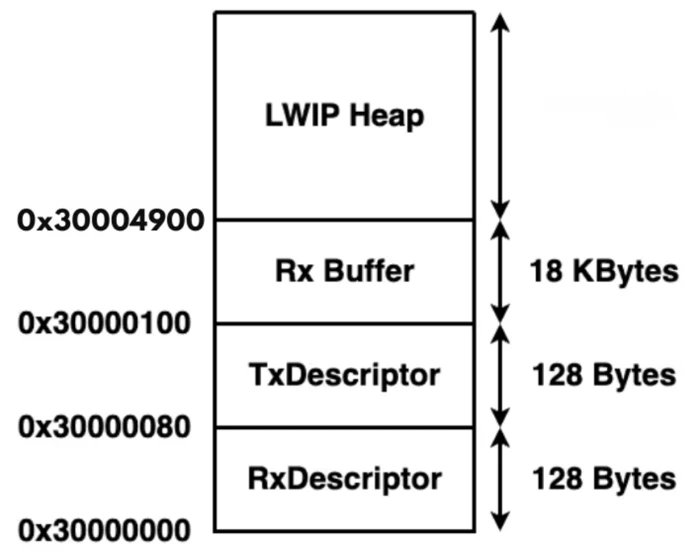
After RX Buffer, we can configure the memory for the LWIP Heap. The image below shows the memory layout for the Ethernet, covering the RX descriptors, TX descriptors, RX buffers, and where the LWIP heap begins.
LWIP Setup (Static IP, Heap, PHY Settings)
Enable LWIP under Middleware for the Cortex-M7 core. The LWIP configuration is shown in the image below.
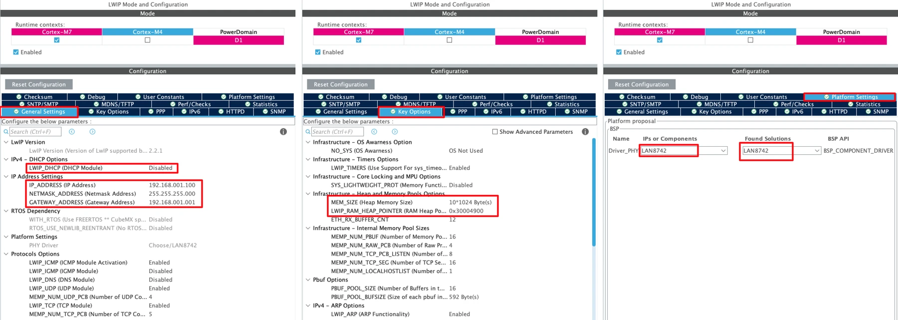
- Here we are going to disable the DHCP, and configure a static IP for our ethernet module. I have set the IP 192.168.1.100 for the board. Also set the Subnet Mask and Gateway address accordingly.
- In the Key Option tab, I am using 10KB memory for the Heap. The location for this heap is defined as 0x30004900. This is the address where the memory occupied by RXBuffer ends.
- In the Platform Settings tab, set the PHY as LAN8742.
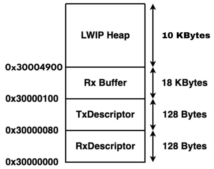
Now the total memory Occupied by the Ethernet and LWIP together is a little over 28 KB. Out of this 256 bytes are occupied by the DMA Descriptors, 18 KB is occupied by the RXBuffer and 10 KB is occupied by the LWIP heap.
Note:
The LWIP heap in CubeMX is often defaulted to 0x30004000, but based on the DMA descriptor layout (RxDescriptor at 0x30000000, TxDescriptor at 0x30000080, RxBuffer at 0x30000100 spanning ~18KB), the heap should start at 0x30004900 to avoid overlapping with the Rx buffer. For small projects this may not cause immediate problems, but it will in larger ones — set it correctly from the start.
MPU Configuration for Cortex-M7 (Cache Coherency Fix)
We have the DMA Descriptors in the SRAM Region. This is why we need to configure the MPU. This is a must for the Cortex-M7 devices, or else you will get hardfault.
We have set up everything in the SRAM (0x30000000). The complete memory structure is shown in the image below.
Below is the image showing the MPU configuration for the above Region. Make sure to enable the Speculation Mode, and Instruction and Data cache as well.
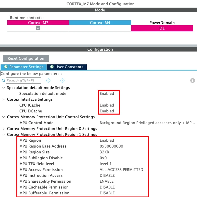
- Here I have selected the 32 KB region so that it will cover our total RAM region, which is around 28 KB.
- The rest of the configuration is to set the region as non-cacheable region.
- This would prevent the cache coherency issue between the CPU and the DMA.
- This is explained in the cortex M7 playlist, so do check that out.
PC Network Configuration (Direct Connection)
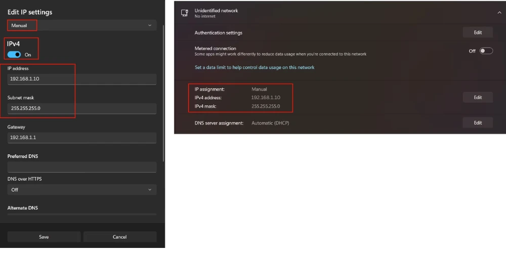
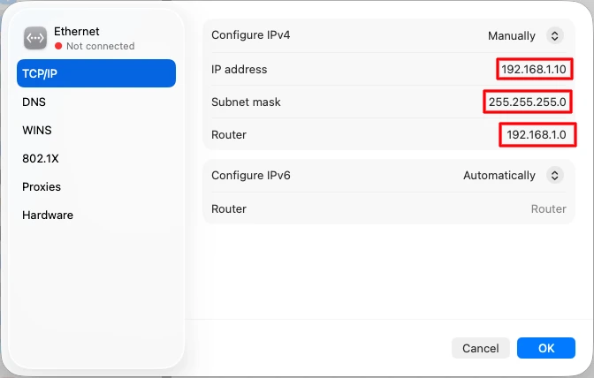
If you are connecting the STM32 board to the Router, there is nothing you need to do at the computer end. But if you are connecting the ethernet cable directly to the computer, you need to configure your computer’s ethernet as per the images shown below.
Below is the configuration for a Windows computer.
Below is the configuration for Mac.
UART Configuration for Logging
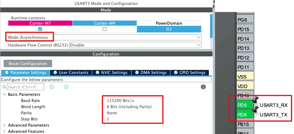
Next, enable UART3 in Asynchronous mode. On the Nucleo H755, PD8 and PD9 connect to the ST-Link virtual COM port, therefore we need to assign these pins for the UART3.
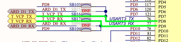
Set the baud rate to 115200, 8-bit word length, no parity, one stop bit.
STM32 Modbus TCP Client Code
Now that we have configured the CubeMX, let’s proceed with implementing the Modbus Client on STM32. CubeMX does not generate everything automatically, and the DMA descriptor sections are not placed in D2 RAM on their own.
Once the project is generated, open the LWIP -> Target -> ethernetif.c file. Here you will some memory locations that needs to be defined in the flash script file.
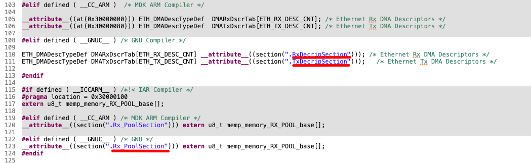
We need to define these memory locations in the flash script file, as per the configuration done in the cubeMX.
Below is the code we need to place in the STM32H755ZITX_FLASH.ld file. These definitions are as per the configuration in the CubeMX. If you are using some other development board, check out the Ethernet Configuration Article.
    .lwip_sec (NOLOAD) : {
    . = ABSOLUTE(0x30000000);
    *(.RxDescripSection)

    . = ABSOLUTE(0x30000080);
    *(.TxDescripSection)

    . = ABSOLUTE(0x30000100);
    *(.Rx_PoolSection)
} >RAM_D2CubeMX only generates the LWIP initialization call, it does not generate the code to run the LWIP. Therefore we will add MX_LWIP_Process() inside the infinite while loop:
while (1)
{
    MX_LWIP_Process();
}We also need a custom _write function so printf output is routed through UART3. This is what lets us view Modbus logs on a serial terminal.
int _write(int fd, unsigned char *buf, int len) {
  if (fd == 1 || fd == 2) {
    HAL_UART_Transmit(&huart3, buf, len, 999);
  }
  return len;
}Modbus Driver Code
Inside the Drivers folder, create a new folder named Modbus, and place all the Modbus-related files inside it. For this part, we need modbus.h, Modbus_Client.h, Modbus_Client.c, Modbus_Client_Parser.h, and Modbus_Client_Parser.c.
Modbus.h
modbus.h holds all the function codes definitions, along with the exceptions. We will use these in the future tutorials of this series.
#ifndef MODBUS_MODBUS_H_
#define MODBUS_MODBUS_H_

#define MB_FC_READ_COILS            0x01
#define MB_FC_READ_DISCRETE_INPUTS  0x02
#define MB_FC_READ_HOLDING_REGS     0x03
#define MB_FC_READ_INPUT_REGS       0x04
#define MB_FC_WRITE_SINGLE_COIL     0x05
#define MB_FC_WRITE_SINGLE_REG      0x06
#define MB_FC_WRITE_MULTI_COILS     0x0F
#define MB_FC_WRITE_MULTI_REGS      0x10


#define MB_EX_ILLEGAL_FUNCTION        0x01
#define MB_EX_ILLEGAL_DATA_ADDRESS    0x02
#define MB_EX_ILLEGAL_DATA_VALUE      0x03
#define MB_EX_SERVER_DEVICE_FAILURE 0x04Modbus_Client.c
Modbus_Client.c file contains all the TCP related functions. These functions helps STM32 to connect to the TCP server and handle the incoming data.
Everything starts with Modbus_Client_Process, whose parameters are the server’s IP address and the port. This function is called repeatedly, right after MX_LWIP_Process, inside the main loop.
Modbus_Client_Process("192.168.1.10", 502);Inside this function, we first wait for the Ethernet interface to become ready. This matters specifically in client mode, since the client is the one initiating the connection, so the link needs to be ready before tcp_connect is called:
if (!netif_is_up(&gnetif) || !netif_is_link_up(&gnetif))
{
    tcp_started = 0;
    return;
}Once the interface is up, we check the tcp_started flag. If this variable is 0, it means either a connection attempt has not been started yet, or a timeout has occured while attempting the connection. In such case, we call tcp_new to create a TCP control block, and then call Modbus_Client_Init to attempt connection to the server.
if (!tcp_started)
{
	printf("\r\natStarting Modbus Client...\r\n");

	if (Modbus_Client_Init(serverIP, port) == ERR_OK)
	{
		tcp_started = 1;
  	tcp_connect_start_tick = HAL_GetTick();
	}

	return;
}The function Modbus_Client_Init converts the server’s IP address from string format to the format LWIP expects, and calls tcp_connect to connect to the server:
err_t Modbus_Client_Init(char *serverIP, uint16_t port)
{
    ip_addr_t destIPADDR;

    ClientPCB = tcp_new();

    if(ClientPCB == NULL)
    {
        printf("ERROR: tcp_new() failed!\r\n");
        return ERR_MEM;
    }

    ipaddr_aton(serverIP, &destIPADDR);

    printf("Connecting to the Server...\r\n");
    printf("IP : %s\r\n", serverIP);
    printf("Port   : %d\r\n", port);

    return tcp_connect(ClientPCB, &destIPADDR, port, tcp_client_connected);
}Once the connection succeeds, tcp_client_connected callback is called. This is where the variable ClientConnected gets set to 1, which the Modbus_Client_Process checks on every call.
If the client is still not connected after calling Modbus_Client_Init, it means the server is either not ready or something went wrong during the connection attempt. Since retrying immediately does not help, a 5 second timeout is used before trying again:
if (!ClientConnected)
{
    if ((HAL_GetTick() - tcp_connect_start_tick) > TCP_CONNECT_TIMEOUT_MS)
    {
        printf("Connection Timeout\r\n");

        tcp_started = 0;
        tcp_retries++;

        if (tcp_retries >= TCP_MAX_RETRIES)
        {
            printf("Maximum retries reached\r\n");
            isServerOK = 0;
        }
    }
}There is also a limit on how many times the client retries, which is currently set to 5. You can increase this if you want the client to keep retrying indefinitely. Once the retry limit is reached, the variable isServerOK is reset to 0, and this entire block stops running. At that point, the board needs to be reset to try connecting again.
Once the client is connected, the tcp_client_connected registers two more callbacks. The callback tcp_recv for handling data received from the server, and tcp_err for handling connection errors.
After registering these callbacks, it sends a test Modbus request. This is to confirm that the server receives and decodes the request correctly. This request will be removed in the upcoming parts once we begin implementing actual function code handling:
uint8_t txBuf[12] =
{
        0x00, 0x01,     // Transaction ID
        0x00, 0x00,     // Protocol ID
        0x00, 0x06,     // Length
        0x01,           // Unit ID
        0x03,           // Function Code
        0x00, 0x00,     // Starting Address
        0x00, 0x10      // Quantity
};
TCP_SendRequest(txBuf, 12);This request uses function code 3 (read holding registers) to request 16 Registers (0x00, 0x10) from the server.
Whenever the client receives data, the callback tcp_client_recv is called. Right now we are not processing this data meaningfully. The callback copies the received bytes into a buffer and passes them to MB_Client_Parser, which is the file we will build out in future parts:
static err_t tcp_client_recv(void *arg, struct tcp_pcb *tpcb, struct pbuf *p, err_t err)
{
    uint8_t rxBuf[260];

    if((err != ERR_OK) || (p == NULL))
    {
        if(p != NULL) pbuf_free(p);
        tcp_client_connection_close(tpcb);
        return ERR_OK;
    }

    tcp_recved(tpcb, p->tot_len);
    pbuf_copy_partial(p, rxBuf, p->tot_len, 0);
    MB_Client_Parser(tpcb, rxBuf, p->tot_len);
    pbuf_free(p);

    return ERR_OK;
}The rest of the file contains the usual supporting functions. tcp_client_connection_close will closes the connection, and tcp_client_error will log any errors to the console. This file will not need any changes in the upcoming parts of this series.
main.c file
Inside the main function infinite loop, after the MX_LWIP_Process, we will call the function Modbus_Client_Process to start the TCP Client.
#include "Modbus_Client.h"

int main(void)
{
    /* ... existing HAL, clock, and Ethernet init ... */
    while (1)
    {
        MX_LWIP_Process();
        Modbus_Client_Process("192.168.1.10", 502);
    }
}Here, 192.168.1.10 is the IP address of my computer, where the Server is running. Also, the server is listening on port 502.
Modbus Client Testing
Since there is no readily available Modbus TCP server application for macOS, I have used a small Python script here instead as the server. This server listens on port 502, decodes whatever request it receives, and prints the details on the console, along with the IP address and port of the connected client.
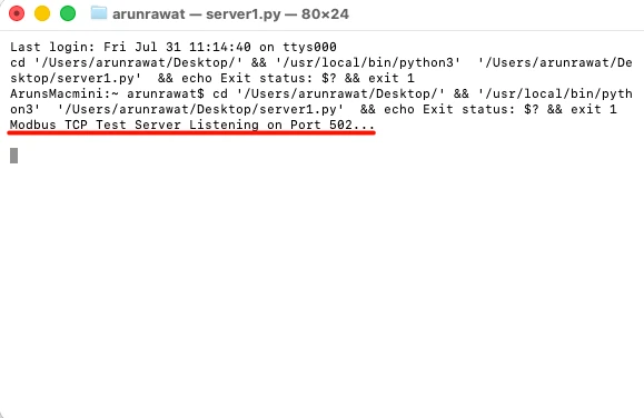
Now the STM32 Client will connect to this server. Once connected, it will send a Modbus format request. The server prints the client information, along with the request sent by it.
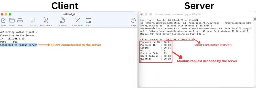
You can see the client successfully connects to the server and the server decoded the request sent by the client. The server (Python server I created for this demo) does not send any response for now. We will start implementing the server response and the response handling from the next tutorial.
With this, the STM32 is now working as a basic Modbus TCP client, capable of connecting to a server and sending a request. In the next part of this series, we will begin adding actual function code handling, starting with reading holding and input registers from the server.
STM32 Modbus TCP Client – Frequently Asked Questions
Conclusion
That covers the basic setup for the STM32 as a Modbus TCP client. We set up the Ethernet peripheral, configured the LWIP stack, and built a client that connects to a server. It also retries on failure, and sends a simple test request. There is no function code handling yet, but the connection logic in Modbus_Client_Process is something we will not need to touch again, since it takes care of establishing and maintaining the connection on its own.
From the next part onward, we will build on top of this same project, adding one function code at a time, starting with reading holding and input registers.
Download STM32 Modbus TCP Client Basic Setup Project
Open source CubeMX project files and HAL source code, tested on real hardware. Free to use — support the work if it helped you.
Browse More STM32 Modbus TCP Tutorials

Subscribe
Login
0 Comments
Newest

