Interfacing MFRC522 RFID Module with STM32 using SPI Communication
In this tutorial, we’ll learn how to interface the MFRC522 RFID module with an STM32 microcontroller using the SPI communication protocol. The MFRC522 is a low-cost RFID reader that operates at 13.56 MHz and is commonly used in access control systems, attendance tracking, and contactless identification projects.
We’ll also discuss how data communication happens between the microcontroller and the RFID reader through the SPI bus. This project is an excellent example of how STM32 can be used in RFID-based embedded applications.
Introduction to MFRC522 and STM32 SPI Interface
What is MFRC522 RFID Module
The MFRC522 is a popular RFID (Radio Frequency Identification) reader module based on the NXP MFRC522 IC. It operates at 13.56 MHz and supports several RFID cards and tags that follow the ISO/IEC 14443A standard, such as MIFARE Classic cards.
This module allows you to read unique identification (UID) numbers stored in RFID cards or tags without any physical contact. Communication happens wirelessly through electromagnetic induction. The module typically has a detection range of about 2–5 cm, making it suitable for secure and short-range identification systems.
The MFRC522 offers a compact, energy-efficient design and supports multiple communication interfaces — SPI, I²C, and UART. Developers commonly use SPI for its speed and simplicity. You can easily interface the MFRC522 with microcontrollers like Arduino, ESP32, and STM32 to build RFID-based security and automation systems.
Why Use MFRC522 with STM32 Microcontroller
Developers widely use the STM32 family of microcontrollers in embedded applications because these devices deliver high performance, consume low power, and offer flexible peripheral configurations. When paired with the MFRC522 RFID module, STM32 can efficiently handle real-time card detection, data exchange, and security verification.
Using STM32 with MFRC522 allows you to:
- Communicate over high-speed SPI for faster card reading.
- Process RFID data in real time using STM32’s powerful ARM Cortex-M core.
- Use multiple GPIOs and peripherals (like UART or LCD) to display or log RFID data.
- Integrate RFID-based authentication or access control into your IoT and automation projects.
This combination makes STM32 a great choice for creating smart access systems, attendance machines, or contactless payment prototypes.
Overview of SPI Communication in STM32
SPI (Serial Peripheral Interface) is a synchronous serial communication protocol that enables a master device to exchange data efficiently with one or more slave devices. It operates using four main signals:
- MOSI (Master Out Slave In) – Data line from STM32 to MFRC522
- MISO (Master In Slave Out) – Data line from MFRC522 to STM32
- SCK (Serial Clock) – Clock signal generated by STM32
- NSS (Slave Select) – Used to enable the MFRC522 during communication
In this project, the STM32 acts as the SPI master, and the MFRC522 module acts as the SPI slave. SPI transfers data on every clock pulse, making it a fast and reliable protocol for RFID communication.
Components and Circuit Connections
Required Components
To interface the MFRC522 RFID module with an STM32 microcontroller using the SPI interface, you’ll need the following components:
- STM32 Development Board – Any STM32 board (e.g., STM32F103C8T6 “Blue Pill” or STM32F4 series).
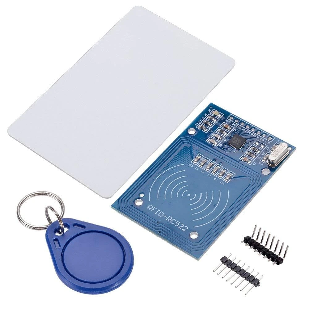
- MFRC522 RFID Module – The 13.56 MHz RFID reader based on the NXP MFRC522 IC.
- RFID Tags or Cards – MIFARE 1K or compatible RFID cards/tags.
- Jumper Wires – For SPI and power connections between STM32 and the RFID module.
- Breadboard – Optional, for easy prototyping and testing connections.
- USB Cable – To connect the STM32 board to your computer for programming and serial monitoring.
MFRC522 Pinout and Description
The MFRC522 RFID module comes with an 8-pin interface, making it easy to connect with various microcontrollers.
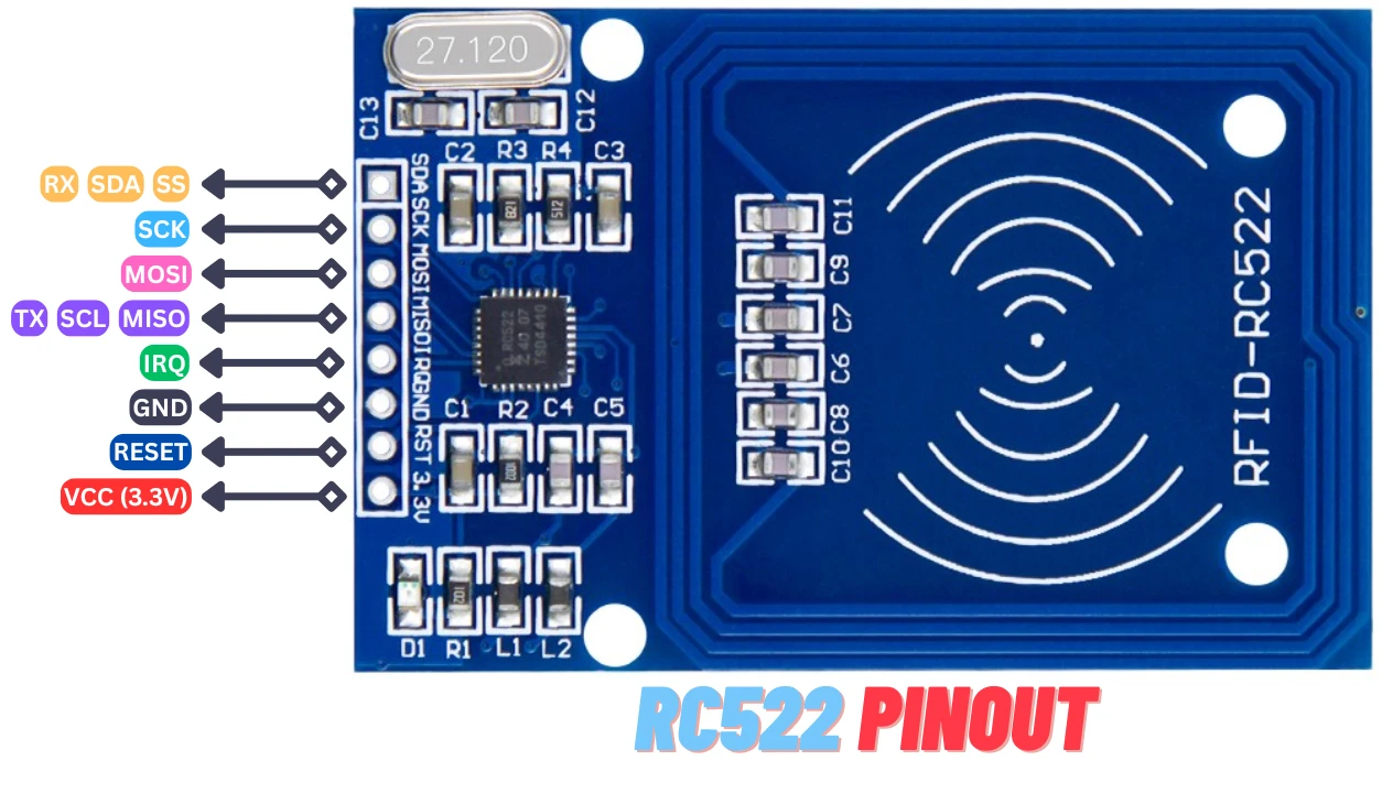
Below is a quick overview of each pin and its function:
| Pin Name | Description |
|---|---|
| VCC | Power supply pin. Connects to 3.3 V (do not use 5 V). |
| RST | Reset pin. Used to reset or initialize the RFID module. |
| GND | Ground connection. |
| IRQ | Interrupt pin (optional). Not required for basic reading operations. |
| MISO | SPI output (Master In Slave Out). Sends data from MFRC522 to STM32. |
| MOSI | SPI input (Master Out Slave In). Sends data from STM32 to MFRC522. |
| SCK | Serial Clock line generated by STM32. |
| SDA / NSS | SPI chip select (Slave Select) pin, used to activate the module. |
Note: The MFRC522 operates only at 3.3 V logic levels. Make sure your STM32 board also runs at 3.3 V to avoid damaging the module.
Circuit Diagram for MFRC522 and STM32 SPI Connection
In this project, the STM32 acts as the SPI master, while the MFRC522 module functions as the SPI slave. The image below shows the connection between STM32 and MFRC522 RFID Module.
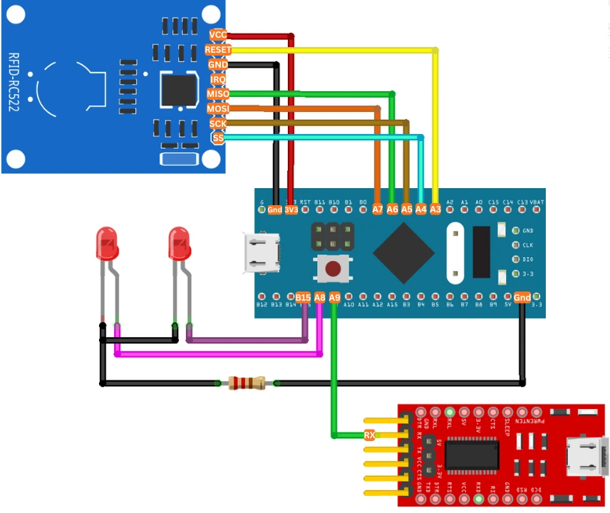
The circuit connection is straightforward:
- Connect the power lines (VCC and GND) with 3.3V and GND respectively. Do not power the module with 5V as it is not tolerant.
- Link the SPI pins from STM32 to corresponding pins on MFRC522.
- Use one GPIO pin for the RST signal.
MFRC522 Connection
Below is the pin-to-pin connection table for reference (example uses STM32F103C8T6):
| MFRC522 Pin | STM32 Pin | Description |
|---|---|---|
| VCC | 3.3 V | Power supply for MFRC522 |
| GND | GND | Common ground |
| RST | PA3 | Reset pin (can be any GPIO) |
| SDA / NSS | PA4 | SPI Chip Select (NSS) |
| MOSI | PA7 | SPI Master Out Slave In |
| MISO | PA6 | SPI Master In Slave Out |
| SCK | PA5 | SPI Clock |
| IRQ | Not Connected | Optional interrupt pin |
LED Connection
Other than the MFRC522 Module, the pins PA8 and PB15 are connected to the LEDs. These LEDs will indicate the status of the card.
FT232 Connection
We will use the FT232 to view user interaction logs on the serial console. Since we only send data from STM32 to the FTDI, connect PA9 (UART1_TX) to the RX pin of the module.
STM32CubeMX Configuration for SPI Interface
Before we can communicate with the MFRC522 RFID module, we need to configure the SPI peripheral in STM32CubeMX.
Clock Configuration
We will start with the clock configuration first. The image below shows the clock configuration for the project.
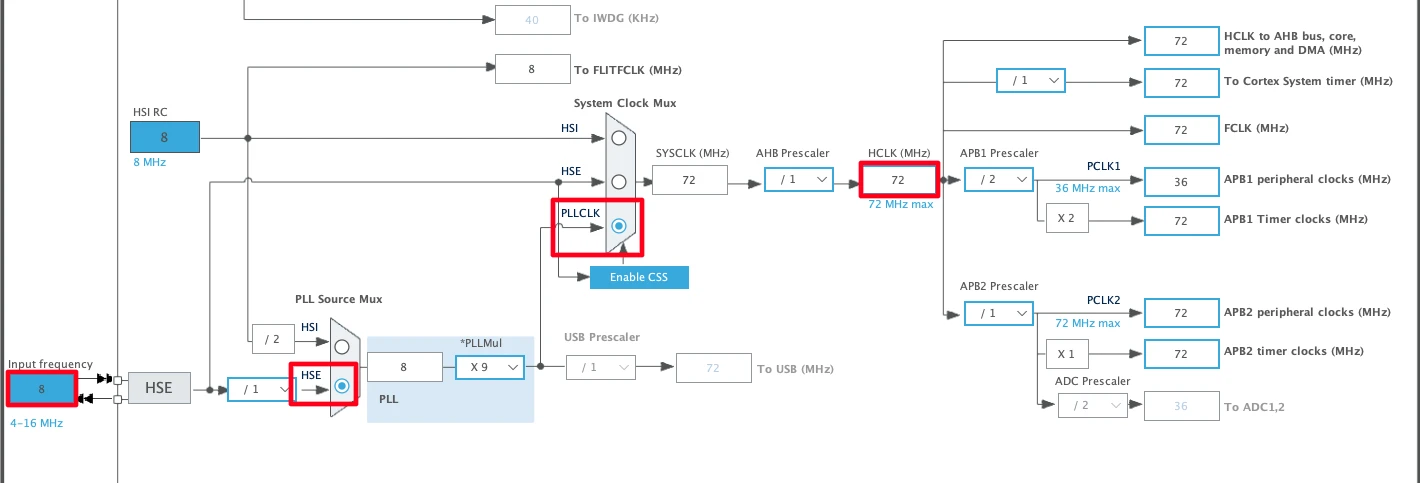
The STM32F103C8 has an external crystal of 8MHz. We will use the PLL to clock the system at maximum 72MHz.
SPI Configuration
The image below shows the SPI configuration.
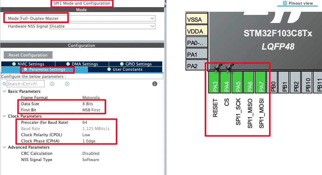
I have configured the Prescaler to 64 to keep the Baud Rate around 1MHz. The Data width is 8 bits with MSB sent first. The SPI mode should be MODE0, so set the CPOL to LOW and CPHA to 1 Edge.
Note that the pins PA5, PA6 and PA7 are configured as the SPI CLK, MISO and MOSI. Other than these I have configured the pins PA4 and PA3 as output. These pins will be used as CS (SPI SS) and RESET pins respectively.
LED Pins Configuration
We will also configure 2 LEDs to indicate the card status. The LEDs will light ON when the respective card is read. This will serve as an indication that the card has been read successfully.
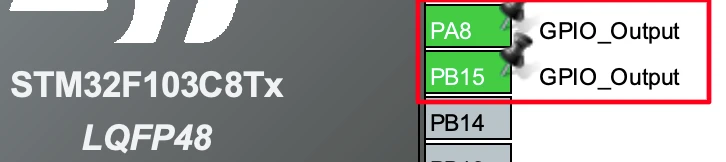
I have configured the pins PA8 and PB15 as output. The LEDs will be connected to these pins.
UART1 (FT232) Configuration
The user interactive logs will be sent through UART1 to the FT232, which will then be displayed on the serial console. The image below shows the UART1 configuration.
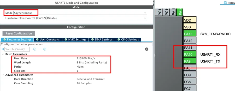
The UART1 is configured in the Asynchronous mode. The Baud rate is set to 115200 Bits/s with 8 Bits of word length, No parity and 1 Stop bit. We can configure this however we want, but this is an optimal configuration.
The pins PA9 and PA10 are configured as the UART1_TX and UART1_RX pins respectively. Since we only need to transmit data to the FTDI, PA9 (UART1_TX) is connected to FTDI RX as mentioned in the wiring diagram.
Interfacing MFRC522 with STM32 using HAL Library
Once the SPI interface is configured, the next step is to integrate the MFRC522 RFID library and write the application code. Using the STM32 HAL library makes this process easier and portable across different STM32 series. Let’s go through each part step by step.
Adding MFRC522 Library Files to STM32 Project
Download the project at the end of this post. You can find the MFRC522_STM32 library files inside the src and inc folders.
Copy the following files into your STM32 project directory:
MFRC522_STM32.cfile to src folder.MFRC522_STM32.h
Now open the main.c file and include the header file as shown below.
#include "MFRC522_STM32.h"Now create a new MFRC522_t structure according to your setup. You need to define the following elements in this structure:
- @hspi is the SPI instance for this project
- @csPort is the GPIO Port for the CS(SS) Pin
- @csPin is the CS Pin itself
- @rstPort is the GPIO port for the RST Pin
- @rstPin is the RST pin itself
I have defined it as per my configuration below.
MFRC522_t rfID = {&hspi1, CS_GPIO_Port, CS_Pin, RESET_GPIO_Port, RESET_Pin};Next, define a custom _write function to route the printf output via the UART. This is necessary for logging the data on the serial console. The library prints the logs using printf function, therefore we need to route its output using the UART.
int _write(int fd, unsigned char *buf, int len) {
  if (fd == 1 || fd == 2) {                     // stdout or stderr ?
    HAL_UART_Transmit(&huart1, buf, len, 999);  // Print to the UART
  }
  return len;
}I have configured UART1 for the logging, hence I am using it here in the function.
Now define an array of 4 bytes to store the ID of the card read by the library.
uint8_t uid[4];Initializing the MFRC522 RFID Module
Before the module can read any RFID tags, it needs to be initialized. The initialization sequence involves setting up SPI communication and configuring internal MFRC522 registers.
In your main() function, after system initialization, add the following lines:
MFRC522_Init(&rfID);The rfID is the MFRC522_t structure we defined above.
This function resets the RFID module, verifies communication, and sets it into idle mode—ready to detect nearby RFID tags. You can view the logs to see if there is any issue with the initialization.
Detecting and Reading RFID Card UID
After initialization, we can start detecting RFID cards placed near the antenna. The MFRC522 continuously scans for tags using its internal RF field. When a tag enters its range, the library can retrieve its unique identifier (UID).
Here’s a simple example code snippet:
	  if (waitcardDetect(&rfID) == STATUS_OK){
		  if (MFRC522_ReadUid(&rfID, uid) == STATUS_OK){
			  USER_LOG("CARD ID:%02X %02X %02X %02X", uid[0], uid[1], uid[2], uid[3]);
			}
		  waitcardRemoval(&rfID);
} The waitcardDetect() function checks if any tag is in range. This function will continue to wait forever until a card is found and returns STATUS_OK on successful card detection.
Next we read the 4-Byte card UID using the function MFRC522_ReadUid. This function will store the UID into the uid array we pass to its parameter. When the UID is read successfully, it will return STATUS_OK. This UID is a unique number associated with each RFID card and can be used for identification, access control, or authentication purposes.
Once the UID is stored in the uid array, we will log it to the console in hexadecimal format. This will help us identify the correct UID for each card.
Finally we will wait for the card to be removed from the module using the function waitcardRemoval(). The function will also wait forever in the while loop for the card to be removed.
Viewing the Card ID on the console
Once the above code is programmed into the STM32F103C8 microcontroller, the following output appears on the serial console.
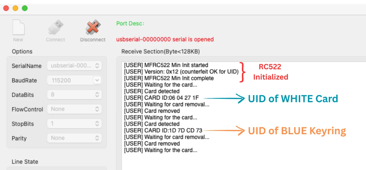
As you can see in the image above, after initializing, the code waits for the card to be placed on the module. Once placed, it outputs the IDs of the White card and Blue keyring that comes with the module itself. These IDs are in the hexadecimal format.
We will now use these IDs to perform some specific actions.
Validating UID via LED Indication
Now that we have obtained the unique IDs of the cards, we can use them to trigger specific actions when each card is scanned by the module. In this example, I will demonstrate this by blinking different LEDs for one second when their corresponding cards are detected.
Below the while loop of the main() function.
  while (1)
  {
	  if (waitcardDetect(&rfID) == STATUS_OK){
		  if (MFRC522_ReadUid(&rfID, uid) == STATUS_OK){
			  USER_LOG("CARD ID:%02X %02X %02X %02X", uid[0], uid[1], uid[2], uid[3]);
			  if ((uid[0] == 0x06) && (uid[1] == 0x04) &&(uid[2] == 0x27) &&(uid[3] == 0x1F)){
				  HAL_GPIO_WritePin(GPIOA, GPIO_PIN_8, GPIO_PIN_SET);
				  HAL_Delay(1000);
				  HAL_GPIO_WritePin(GPIOA, GPIO_PIN_8, GPIO_PIN_RESET);
			  }

			  else if ((uid[0] == 0x1D) && (uid[1] == 0x7D) &&(uid[2] == 0xCD) &&(uid[3] == 0x73)){
				  HAL_GPIO_WritePin(GPIOB, GPIO_PIN_15, GPIO_PIN_SET);
				  HAL_Delay(1000);
				  HAL_GPIO_WritePin(GPIOB, GPIO_PIN_15, GPIO_PIN_RESET);
			  }
		  }
		  waitcardRemoval(&rfID);
	  }
}After the card is detected, we will check if the UID of the card. We already have the UIDs from the first test, 06 04 27 1F (WHITE CARD) and 1D 7D CD 73 (Blue Keyring). When either of these IDs are matched, we will blink the respective LED for 1 second.
The gif below shows the output of this code.

As shown in the GIF, when the white card is scanned by the MFRC522 module, the green LED turns ON for one second. Similarly, when the blue keyring is scanned, the red LED turns ON.
This confirms that both cards can be configured to trigger specific actions upon detection. Instead of controlling LEDs, you can extend this concept to perform various tasks — for example, unlocking a door, enabling access to a restricted area, logging attendance, or activating a particular device connected to the microcontroller.
Project Ideas & Extensions
Once you have successfully interfaced the MFRC522 RFID module with the STM32 via SPI and verified that it can read card UIDs, you can extend this basic setup into several practical and real-world projects. Below are a few popular ideas that will help you make the most out of your RFID system.
Door Lock or Relay Control System
You can easily convert your RFID reader setup into a smart door lock or relay control system.
- How it works: Store the UID (Unique Identifier) of authorized cards in your code or an external memory. When an authorized card is detected, the STM32 activates a GPIO pin connected to a relay or solenoid lock for a few seconds.
- Hardware additions: Relay module, solenoid door lock, or servo motor for mechanical locking.
- Features you can add:
- EEPROM-based UID storage for adding/removing users without reflashing firmware.
- Real-time access logging using UART or SD card.
- Visual and audio feedback using LEDs and buzzers.
- Applications: Smart home door locks, access-controlled cabinets, or lab entry systems.
Attendance Logging via SD Card or Network
The MFRC522 can also be integrated into an attendance management system, where each scanned card logs an entry event.
- Local Logging (SD Card):
Save each card’s UID, timestamp, and access status to a file on an SD card using the SPI-based SD interface. This data can later be read on a computer for analysis. - Network-Based Logging (Ethernet/Wi-Fi):
Combine STM32 with an ESP8266, ESP32, or W5500 Ethernet module to send log data directly to a web server or Google Sheets through an API. - Enhancements:
- Real-time clock (RTC) module (like DS3231) for accurate timestamps.
- LCD or OLED display for user feedback.
- Web dashboard for viewing attendance records.
Multi-Card Handling with a Table of UIDs
Instead of using a single predefined card, you can maintain a table or list of authorized UIDs.
- Implementation:
- Store multiple UIDs in a C array or external EEPROM/Flash.
- When a card is scanned, the system checks if the UID matches any stored entry.
- Advantages:
- Enables multi-user access systems.
- Easy to manage large groups (e.g., employees, students).
- Can assign different permissions or actions for different cards.
- Example:
- Card A → Opens Door 1
- Card B → Opens Door 2
- Card C → Triggers Alarm or Logs Entry
Integrating with Other SPI Devices (Conflict Handling)
In complex projects, you may need to interface multiple SPI devices with STM32 — for example, an MFRC522, SD card module, and an external display.
- Challenge: All devices share the same SPI bus (MOSI, MISO, SCK) but require independent Chip Select (CS) lines.
- Best Practices:
- Assign a separate CS pin for each SPI device and ensure only one is active (LOW) at a time.
- Carefully configure SPI mode and clock speed — some devices may require different settings.
- Use mutex or semaphore control if running under FreeRTOS to prevent bus conflicts.
- Example Use Case:
- The MFRC522 reads a card → STM32 logs data to SD card via SPI → Displays confirmation on an SPI OLED screen.
Video Tutorial
STM32 MFRC522 RFID Interface Video Tutorial
This tutorial demonstrates how to interface the MFRC522 RFID module with the STM32 using the SPI protocol. Along with the detailed written guide, I’ve also prepared a hands-on video showing the complete setup, code, and testing process. Watch the video below and follow along with your own hardware.
Watch the STM32 MFRC522 TutorialConclusion
In this tutorial, we interfaced the MFRC522 RFID module with the STM32 using SPI communication, read card UIDs, and triggered actions based on scanned tags.
This setup can be easily extended to real-world applications such as RFID-based door locks, attendance systems, or access control projects. With STM32’s performance and MFRC522’s versatility, you can build reliable and scalable RFID solutions for any embedded application.
Browse More STM32 SPI Tutorials
No post found!
STM32 MFRC522 RFID Project Download
STM32 MFRC522 FAQs

