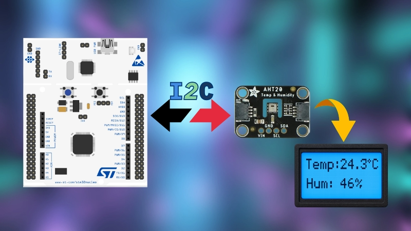
Interface AHT20 Sensor with STM32 Using I2C
In this tutorial you will learn how to interface the AHT20 temperature and humidity sensor with STM32 using I2C. This tutorial includes circuit diagram, datasheet-based code, and project files to download at the end of the post.
VIDEO TUTORIAL
You can check the video to see the complete explanation and working of this project.
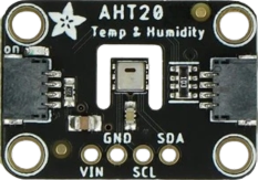
Introducing AHT20 Temperature & Humidity sensor
AHT20 is small in size, and is relatively easy to interface compared to other temperature sensors we have interfaced before. It is a digital temperature and humidity sensor that offers high accuracy, fast response, and stable performance. It communicates via the I2C interface, making it ideal for embedded systems like STM32.
The Temperature resolution of the sensor is 0.01°C whereas the humidity resolution is 0.024%RH.
Here are the important features of the AHT20 sensor:
- High accuracy: ±0.3°C temperature, ±2% RH humidity
- I2C communication interface for easy integration
- Wide operating voltage: 2.2V to 5.5V
- Fast response and low power consumption
WIRING DIAGRAM
The sensor works with I2C hence the connection is very straightforward. Below is the image showing the connection between AHT20 and STM32F103.
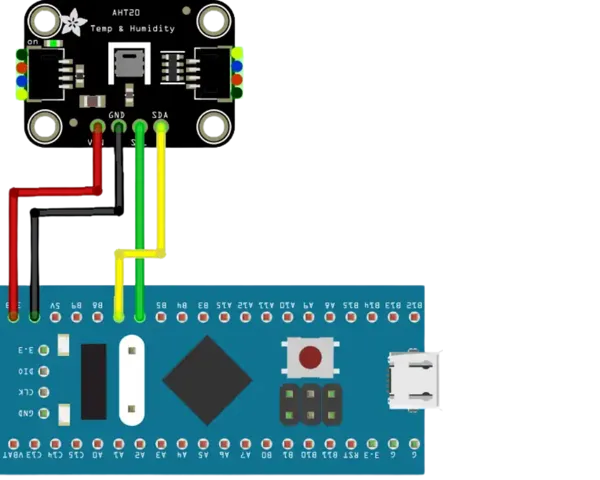
The table below describes the pin connection.
| AHT20 Pin | Function | Connected to STM32 |
|---|---|---|
| VCC | Power Supply (3.3V/5V) | 3.3V |
| GND | Ground | GND |
| SDA | I2C Data Line | PB7 |
| SCL | I2C Clock Line | PB6 |
CUBEMX CONFIGURATION
Clock Configuration
Below is the image showing the clock configuration for the project.
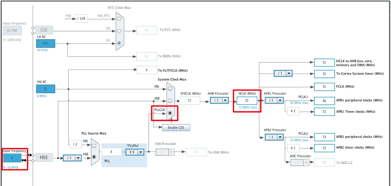
The STM32F103C8T6 board has 8Mhz crystal on it. We will use this External HSE to run the system at maximum 72Mhz.
The rest of the clocks are unmodified.
I2C Configuration
Below is the image showing the I2C configuration for the project.
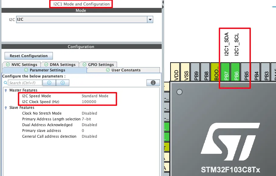
I am using I2C1 for the project. The I2C is configured in the default mode (Standard) with clock speed set to 100Khz.
The Pins PB6 and PB7 are configured as the I2C Clock and Data pins respectively.
THE CODE
We will write the code by referring to the datasheet of the sensor.
Definition
Let’s start with some definitions that we will use in the project.
#include "math.h"

#define AHT20_ADDRESS 0x38<<1
float Temperature, Humidity;The 7bit AHT20 device address is 0x38. This is mentioned in the datasheet of the sensor. The HAL library uses 8bit device address, that includes the 7bit address along with the Read/Write bit. This is why we need to shift the address by 1 place to the left (0x38<<1).
The variables Temperature and Humidity will be used to store the final calculated values.
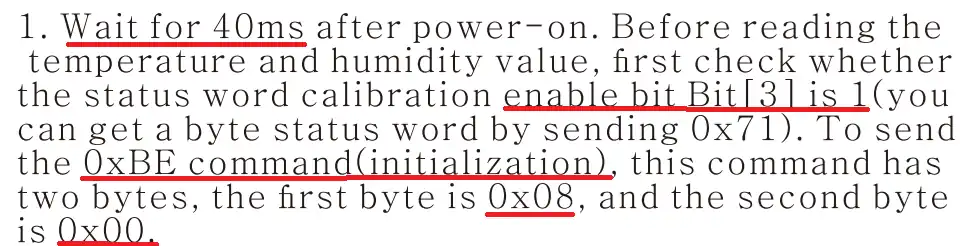
AHT20 Initialization
Below is the image showing the process to initialize the sensor as per the datasheet.
Below is the function to initialize the sensor.
void AHT20_Init (void)
{
	HAL_Delay(40);
	uint8_t status;
	HAL_I2C_Mem_Read(&hi2c1, AHT20_ADDRESS, 0x71, 1, &status, 1, 1000);
	if ((status>>3 & 0x01) == 0)  // if CAL = 0
	{
		uint8_t init_commands[3] = {0xBE, 0x08, 0x00};
		HAL_I2C_Master_Transmit(&hi2c1, AHT20_ADDRESS, init_commands, 3, 1000);
		HAL_Delay (10);
	}
}As per the instructions in the datasheet,
- We will first wait for 40ms.
- Then Read the status register (0x71). The bit 3 (CAL) of this register indicates whether the sensor is calibrated or not.
- If the CAL bit is 0, it means that the sensor is not calibrated and hence we need to initialize it.
- The initialization command, 0xBE, has 2 parameters, 0x08 and 0x00. We will send these 3 bytes to the sensor.
- At last wait for 10ms for the initialization to complete.
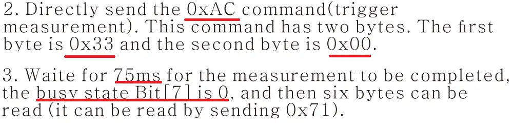
Reading Data
Below is the image showing the process to read the data.
We will write a separate function to read the data from the device.
void AHT20_Measure (void)
{
	uint8_t measure_command[3] = {0xAC, 0x33, 0x00};
	HAL_I2C_Master_Transmit(&hi2c1, AHT20_ADDRESS, measure_command, 3, 1000);
	HAL_Delay(80);

	uint8_t status;
	do {
		HAL_I2C_Mem_Read(&hi2c1, AHT20_ADDRESS, 0x71, 1, &status, 1, 1000);
		HAL_Delay(100);
	}
	while ((status>>7 & 0x01) == 1);

	uint8_t RxData[7];
HAL_I2C_Master_Receive(&hi2c1, AHT20_ADDRESS, RxData, 7, 1000);Here we will follow the steps as per the datasheet.
- Send the “trigger measurement” command (0xAC) along with its parameters.
- Wait for 80ms for the measurement to complete.
- Then continuously read the status register (0x71) and check its 7th bit (BUSY). The loop will only exit if the BUSY bit is 0, indicating that the device has finished the measurement.
- Then we will read 7 bytes of data from the slave device.
These 7 bytes of data contains 1 State Byte + 2 Humidity Bytes + 1 Humidity & Temperature Byte combined + 2 Temperature Bytes + 1 CRC Byte. This is shown in the image below.
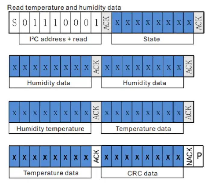
We can ignore the State byte and the CRC Byte, therefore we only have to work with the rest 5 data bytes. In total we have 20Bits of Humidity data and 20Bits of Temperature data.
	uint32_t HUM_DATA = (RxData[1]<<16)|(RxData[2]<<8)|RxData[3];  // accumulated 24bit data
	HUM_DATA = HUM_DATA>>4;  // 20bit data
Humidity = (float) ((HUM_DATA/pow(2,20)) * 100);We will first combine the 2 Humidity data bytes and 1 combined byte to make a 24bit data. This 24 bit data also contains the 4bits of the temperature data, as they are part of the combined data byte. Therefore we will shift the 24bit data to the right by 4 places, so to discard the 4 least significant bits, i.e. the temperature data bits.
We now have the 20bit Humidity data so we will convert it to the %RH format by using the formula given in the datasheet of the sensor.
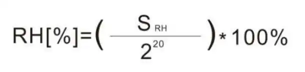
We will use the above formula to convert the Humidity data into the %RH. The converted value will be stored in the Humidity variable.
Similarly, We will first combine the temperature bytes to make a 24 bit temperature data.
	uint32_t TEMP_DATA = (RxData[3]<<16)|(RxData[4]<<8)|RxData[5];  // accumulated 24bit data
	TEMP_DATA = TEMP_DATA&0xFFFFF;  // first 20bit data
	Temperature = (float) (((TEMP_DATA/pow(2,20)) * 200) - 50);
}This 24 bit data also contains the 4bits of the humidity data, as they are part of the combined data byte. Therefore we will perform an AND operation with 0xFFFFF, so to discard the 4 most significant bits, i.e. the humidity data bits.
We now have the 20bit Temperature data so we will convert it to the °C format by using the formula given in the datasheet of the sensor.
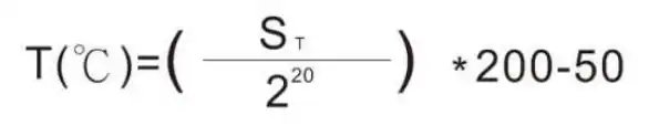
We will use the above formula to convert the Humidity data into the °C. The converted value will be stored in the Temperature variable.
The main function
Inside the main function we will initialize the AHT20 sensor. The read the data continuously in the while loop every 2 seconds.
int main()
{
  .....
  AHT20_Init();
  while (1)
  {
	  AHT20_Measure();
	  HAL_Delay(2000);
  }
}RESULT
Below is the image showing the Temperature and Humidity values in the cubeIDE debugger.
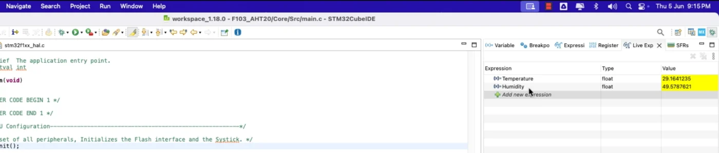
You can see the current temperature and humidity values are displaying in the live expression.
PROJECT DOWNLOAD

