STM32 USB CDC Tutorial: Device and Host Mode Communication Example
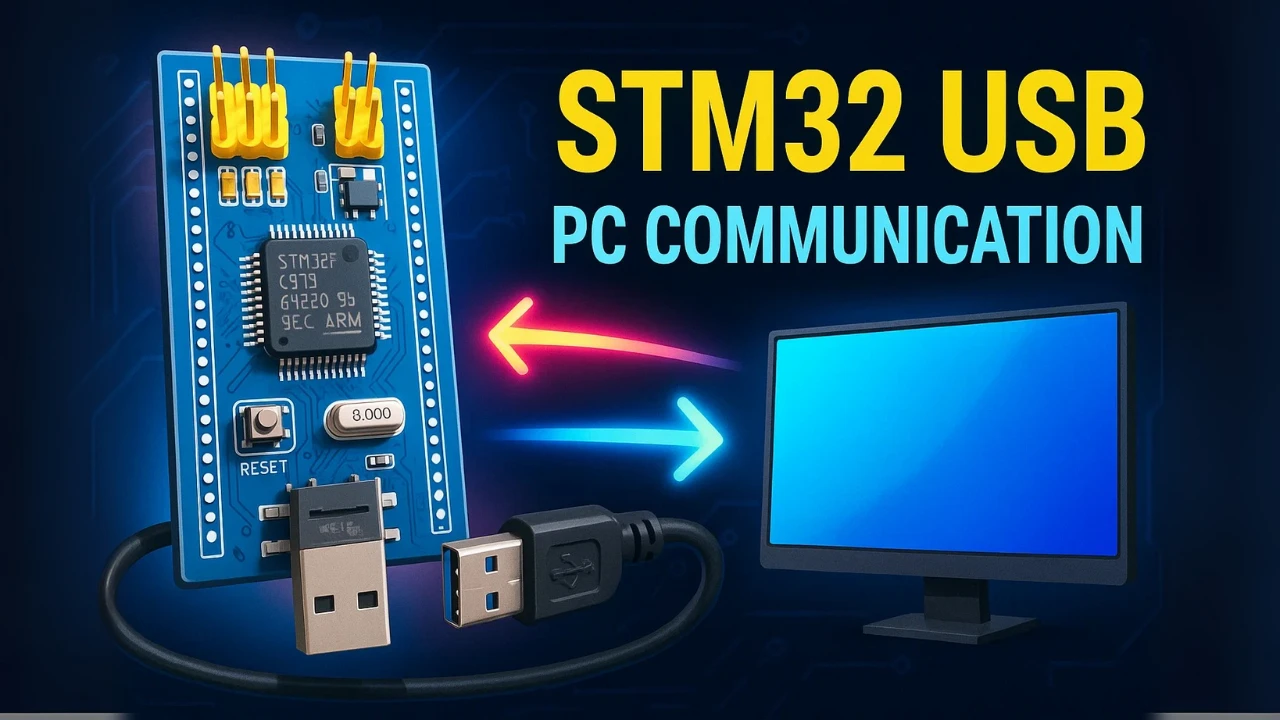
Learn how to set up STM32 USB CDC (Communication Device Class) in both Device and Host modes. This tutorial covers a real-world USB CDC example in STM32, where an STM32F411 acts as a host and STM32F103 as a USB device. You’ll learn about CDC data transfer, VBUS control, pin configuration, and transmitting data using the USB OTG FS interface and STM32CubeMX + HAL.
To better understand the steps, I’ve also created a detailed walkthrough video. You can follow along with the explanations below while watching the video here:
In this tutorial, I will show you how to use USB CDC (Communication Device Class) in STM32 in both modes – Device and Host.
For the Host, I will use the STM32F411 Discovery board, and for the Device, I will use the STM32F103C8T6. Once set up, the two boards will communicate with each other over USB.
You will learn how to:
- Configure STM32 as a USB CDC Device (virtual COM port).
- Configure STM32 as a USB CDC Host.
- Exchange data between the two boards over USB.
By the end, you’ll see a working example of USB communication between STM32F411 and STM32F103.
What is USB CDC in STM32? (Overview of Communication Class)
USB CDC (Communication Device Class) is a standard defined by the USB specification to emulate serial communication ports over USB. In simple terms, it allows a USB connection to behave like a traditional UART/RS232 serial port. This makes it very convenient for developers who want to exchange data without adding extra hardware like USB-to-UART converters.
In the context of STM32 microcontrollers, USB CDC is widely used to create virtual COM ports. With this feature, your STM32 board can communicate directly with a PC or even another STM32 board using just a USB cable. Depending on the project requirements, STM32 can work in both CDC Device mode and CDC Host mode.
Why USB CDC is useful in STM32 projects:
- Serial communication over USB → No need for additional UART hardware.
- Debugging and logging → Developers often use CDC to send debug messages or logs to a PC terminal.
- Sensor data streaming → Useful for real-time data transfer from STM32 to PC or another host.
- Firmware flexibility → Virtual COM ports are recognized by most operating systems without special drivers.
- Two-way communication → Enables both sending and receiving data, just like a standard UART port.
How STM32 simplifies USB CDC setup:
- STM32CubeMX provides middleware support for USB CDC, making the setup straightforward.
- HAL libraries handle low-level USB protocol details, so developers can focus on application code.
- Autogenerated USB stack includes all the necessary descriptors and drivers for CDC operation.
- Cross-compatibility → Works across many STM32 families (F1, F4, H7, etc.) with minimal changes.
STM32 USB CDC Host Setup (F411 Example)
In this part, we will configure the STM32F411 Discovery board to act as a USB CDC Host. The Host will detect the connected STM32F103 Device and establish communication over USB.
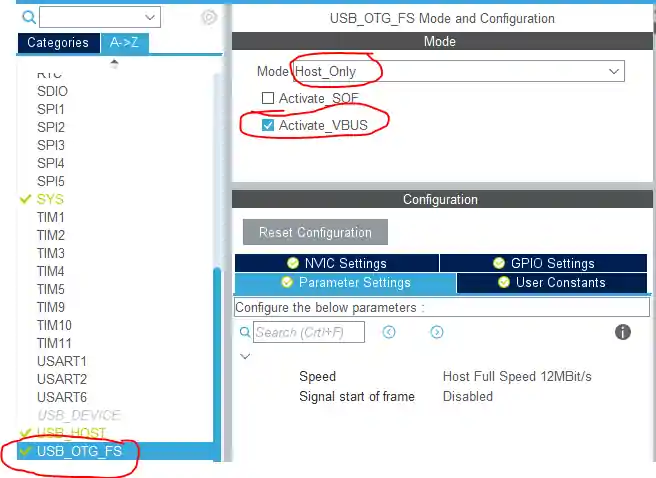
First, select the USB_OTG_FS in Host Only mode. Also, enable the VBUS, since the Host is responsible for supplying power to the connected USB Device.
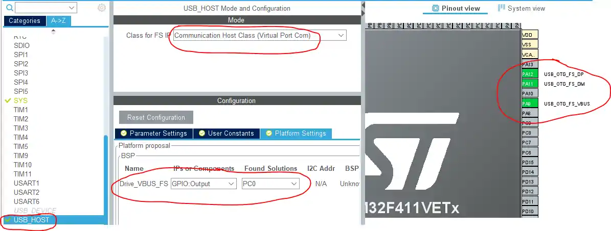
Next, enable USB_HOST and set the class to Communication Host Class. Keep the remaining settings as default.
On the right, you will notice that the required pins are automatically assigned. Additionally, configure PC0 as an output pin, which will be used to control VBUS activation (explained later).
As we need to enable the voltage supply to the VBUS pin, and to do that, take a look at the board schematics. I am using STM32F4 discovery board, and it have the USB schematic as shown below.
As you can see above, the VBUS Voltage is controlled by the PC0 pin. Which is connected to the EN Pin, which is an active Low pin. This means in order to supply the voltage to the VBUS, we must Pull down the PC0 Pin, or basically Set it LOW.
That’s all for the HOST setup, now let’s take a look at the device setup
STM32 USB CDC Device Configuration (F103 Setup)
In this section, we will configure the STM32F103 to work as a USB CDC Device. This setup will allow the F103 to communicate with the Host (STM32F411) over USB, sending and receiving data as a virtual COM port.
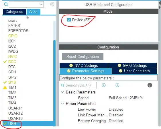
Select the Device mode in the STM32F103 USB Settings
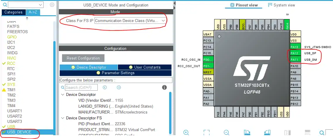
In USB_DEVICE, choose the Communication Device Class and keep all other settings as default.
On the right, you will notice that two pins are automatically assigned for the USB connection.
This is all for the CDC Device Setup.
Wiring Diagram
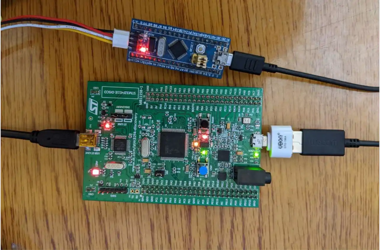
In this setup, the STM32F4 Discovery board (F411) is configured as the USB Host, while the STM32F103 (Blue Pill) acts as the USB Device.
- The two boards are directly connected using a USB cable.
- The F411 Discovery (Host) provides the VBUS power to the F103 (Device).
- The USB D+ and D- lines handle the actual data communication between them.
USB CDC Host Code (STM32 HAL Example)
Below are some definitions, that will be used in the code
extern USBH_HandleTypeDef hUsbHostFS;
extern ApplicationTypeDef Appli_state;
extern USBH_StatusTypeDef usbresult;

#define RX_BUFF_SIZE   64  /* Max Received data 1KB */

uint8_t CDC_RX_Buffer[RX_BUFF_SIZE];
uint8_t CDC_TX_Buffer[RX_BUFF_SIZE];

typedef enum {
  CDC_STATE_IDLE = 0,
  CDC_SEND,
  CDC_RECEIVE,
}CDC_StateTypedef;

CDC_StateTypedef CDC_STATE = CDC_STATE_IDLE;The CDC_HANDLE() function will handle the data transmission in the host.
uint8_t i=0;
void CDC_HANDLE (void)
{
	switch (CDC_STATE)
	{
	case CDC_STATE_IDLE:
	{
		  USBH_CDC_Stop(&hUsbHostFS);
		  int len = sprintf ((char *)CDC_TX_Buffer, "DATA = %d", i);
		  if (USBH_CDC_Transmit (&hUsbHostFS, CDC_TX_Buffer, len) == USBH_OK)
		  {
			  CDC_STATE = CDC_RECEIVE;
		  }
		  i++;
		  break;
	}

	case CDC_RECEIVE:
	{
		  USBH_CDC_Stop(&hUsbHostFS);
		  usbresult = USBH_CDC_Receive(&hUsbHostFS, (uint8_t *) CDC_RX_Buffer, RX_BUFF_SIZE);
		  HAL_Delay (1000);
		  CDC_STATE = CDC_IDLE;
	}

	default:
		  break;
	}
}- When the Host is IDLE, it will send the data to the Device.
- Once the data transfer is successful, it will change the CDC state to RECEIVE mode.
- In the Receiving state, Data will be received from the device, and stored in the CDC_RX_Buffer.
- The state will be again changed to IDLE, so that the next data can be transmitted.
This will creates a continuous communication loop between the Host (F411) and the Device (F103).
Inside the while loop, we will keeps the USB Host running. When the connected device is ready, it starts handling CDC communication.
  while (1)
  {
    /* USER CODE END WHILE */
    MX_USB_HOST_Process();

    if (Appli_state == APPLICATION_READY)
    {
    	CDC_HANDLE();
    }
}USB CDC Device Code (CDC_Receive_FS Example)
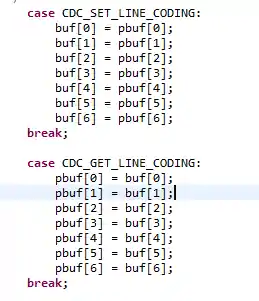
In the CDC Device (STM32F103), the first step is to configure the Line Coding.
To do this, open the file: USB_DEVICE → App → usbd_cdc_if.c
For handling data transfer, the important function is CDC_Receive_FS, which is responsible for receiving data from the Host and then sending it back.
static int8_t CDC_Receive_FS(uint8_t* Buf, uint32_t *Len)
{
  /* USER CODE BEGIN 6 */
  USBD_CDC_SetRxBuffer(&hUsbDeviceFS, &Buf[0]);
  USBD_CDC_ReceivePacket(&hUsbDeviceFS);
  uint16_t len = *Len;
  CDC_Transmit_FS (Buf, len);
  return (USBD_OK);
  /* USER CODE END 6 */
}Here’s what happens step by step:
- The USB stack passes the received data into CDC_Receive_FS.
- The function sets the receive buffer using
USBD_CDC_SetRxBuffer(). - The packet reception is confirmed with
USBD_CDC_ReceivePacket(). - The length of the received data is stored in
len. - Finally, the same data is sent back to the Host using CDC_Transmit_FS().
Basically, whenever the device gets the receive request, it will receive the data, and transmit it back to the host using CDC_Transmit_FS function.
RESULT
The data is first transmitted by the Host (STM32F411). It is then received by the Device (STM32F103) and transmitted back to Host.
The image below shows the data received by the Host.
As you can see above that the CDC_RX_Buffer have received the data (DATA = 0), that we transmitted to the device.
In this STM32 USB CDC example, we demonstrated full communication between a USB host and a CDC device using STM32F411 and STM32F103 boards. With correct setup of VBUS, pin mapping, and HAL-based transmission/reception code, you can build reliable USB communication systems using the Communication Device Class. This approach is perfect for building custom USB peripherals or PC-like interfaces in embedded systems.
Other STM32 USB Tutorials
STM32 USB HOST MSC
STM32 USB HOST HID
Emulate STM32F103 as a MOUSE
How to use STM32 as a KEYBOARD
STM32 USB CDC Tutorial: Send & Receive Data Without UART
WavePlayer using STM32 Discovery
PROJECT DOWNLOAD
Info
You can help with the development by DONATING Below.
To download the project, click the DOWNLOAD button.
Project FAQs
Yes, it can. Since USB and UART/SPI are handled by different peripherals, they can run in parallel. However, you must carefully manage buffer sizes and DMA/interrupt priorities to avoid data loss during heavy transfers.
Instead of sending large buffers directly, implement a chunking mechanism. Break the data into smaller packets aligned with the USB endpoint size (typically 64 bytes for Full-Speed). Also, use circular buffers with DMA to ensure smooth reception.
Yes, but not directly with CubeMX auto-generated code. You need to reinitialize the USB peripheral and descriptors when changing roles. This often requires a custom USB stack modification and careful handling of VBUS detection.
It depends on your timing requirements. USB Full-Speed CDC typically supports ~1 MByte/s throughput. For real-time logging, it’s efficient enough for many sensors, but you must use double buffering and ensure the USB IRQ has high priority.
You can achieve this by modifying the USB descriptors (VID, PID, and string descriptors) and providing a custom INF driver file for Windows. This way, instead of showing as a generic COM port, it can appear under your project’s name.



I am trying to config OTG_FS_DCFG regsister when device receive a SET_ADDRESS command but i can not change condition bit 7 to bit 12, pls help me
What is the reason for putting USBH_CDC_Stop before Receive?
Hi CT.
Ur Demo was very helpful.i m configuring host on stm32 f767zit6, I’m able to transmit the data from host ,bunt unable to receive on the host, can u please help me with this.
when i connect the micro-usb cable ,there is nothing as appearance in device manager.
how can i solve it ???
hello i have same problem, how do you resolved yours?
The micro cable is connected between F103 and F411. It is not connected to the computer
Hi! I see that you keep the ST link usb for power supply and the micro usb for communication, is there a possibility to supply the microcontroller by using only the micro usb? Thank you
Great job!
Did you have an idea, How to set the baud rate and the configuration of “ATmega16U2 (usb/serial bridge of Arduino uno)” by stm32f407g-disc1 USB as a HOST using CDC class?
Thank you for your very useful information
Thanks for the demo. I tried the host setup with Nucleo-L4R5ZI but I get three errors:
1) undefined reference to ‘usbresult’
2) Core/Src/main.o: in function ‘CDC_HANDLE’:
3) make: *** [makefile:69: Nucleo0L4R5Zi-USB-Host.elf] Error 1
Could you give some guidance? Thank you for all the information.
Very helpful. Thankyou.