Published: December 28, 2023
Last Updated: February 22, 2026
Last Updated: February 22, 2026
How to Configure UART & Transmit Data in STM32
This tutorial explains how to configure UART in STM32 using STM32CubeMX and transmit data using HAL UART functions. It covers basic UART setup, selecting the correct baud rate, and sending strings or numbers through the STM32 UART peripheral in blocking mode. This is the first step in learning serial communication with STM32, ideal for beginners looking to interface STM32 with a computer or external modules using UART.
This is the first tutorial in our series on the UART peripheral in STM32 microcontrollers. In this tutorial, you will learn how to set up UART communication in STM32 using STM32CubeMX and send data using the HAL UART function.
Here are some more STM32 UART tutorials you may find useful:
- UART with Interrupt and DMA: Learn how to send data without blocking the CPU using interrupt and DMA.
- How to Receive Data using UART: Learn how to receive data over UART.
Introduction to STM32 UART
The UART (Universal Asynchronous Receiver/Transmitter) peripheral in STM32 microcontrollers provides a simple and efficient way to perform serial communication. It allows data exchange between the microcontroller and other devices such as PCs, GPS modules, Bluetooth modules, or other microcontrollers using standard asynchronous protocols.
UART communication is asynchronous, meaning it doesn’t require a separate clock line—only TX (Transmit) and RX (Receive) lines are used. STM32 MCUs often provide multiple UART/USART interfaces, and they can be configured using STM32CubeMX and HAL libraries to suit different baud rates, word lengths, parity, and stop bits.
STM32 supports both UART and USART peripherals, where USART adds synchronous mode (with a clock line) in addition to asynchronous UART mode.
Features of STM32 UART:
- Configurable Baud Rate
Supports a wide range of baud rates (e.g., 9600 to 1+ Mbps), allowing flexible communication speed based on the application. - Full-Duplex Communication
Simultaneously sends and receives data through separate TX and RX lines. - Interrupt and DMA Support
UART can be operated in polling, interrupt-driven, or DMA mode for efficient, low-latency data handling. - Flexible Frame Format
Supports custom configurations like 8/9 data bits, 1/2 stop bits, and optional parity for error checking.
UART vs USART
UART stands for Universal Asynchronous Receiver Transmitter whereas the USART stands for Universal Synchronous Asynchronous Receiver Transmitter. The term Synchronous enables the USART to send an additional clock signal to the receiving device. The data is then sampled at a predefined edge (Rising or Falling) of the clock. The USART mode uses 3 pins (clock, Tx and Rx) compared to the 2 pins (Tx and Rx) used in the UART.
The most widely used synchronous communications are I2C, SPI, etc. The USART, in a way, can act as the SPI master to send the data to the slave. The synchronous communication is also used when communicating with a smartcard.
The table below shows the comparison between UART and USART in STM32.
| Feature | UART | USART |
|---|---|---|
| Full Form | Universal Asynchronous Receiver Transmitter | Universal Synchronous/Asynchronous Receiver Transmitter |
| Communication Type | Asynchronous only | Supports both Synchronous and Asynchronous |
| Clock Signal | Not used | Uses an additional clock line in synchronous mode |
| Number of Pins Used | 2 (TX and RX) | 3 in synchronous mode (TX, RX, and CLK) |
| Data Sampling | Based on start and stop bits (internal clock) | Data is sampled on the rising or falling edge of external clock |
| Application Example | Basic serial communication with PCs, Bluetooth modules | Smartcard communication, SPI-like data transfers |
| Acts Like SPI Master? | No | Yes, in synchronous mode |
| Use of Start/Stop Bits | Required for data framing | Optional in synchronous mode |
We will use the UART for the major part of this series as it has wider applications compared to the USART.
Why use UART in STM32 projects
UART is very useful in STM32 projects because it is simple, reliable, and supported by many devices. You can use UART to:
- Send debug messages to a serial terminal on your PC
- Connect STM32 to modules like GPS, GSM, or Bluetooth
- Transfer sensor data to another microcontroller
- Communicate with external devices without complex wiring
Another reason to use UART is that it works with only two wires: TX (transmit) and RX (receive). This makes hardware connections easy. Also, STM32 HAL provides ready-to-use functions like HAL_UART_Transmit, so you can start sending data with just a few lines of code.
STM32 UART Hardware Setup
We will use the STM32 MCU to send the data to the computer. Some of the Nucleo and Discovery dev boards from ST supports the virtual com port. This feature enables the USB connected for the ST-link to be also used for the data transmission between the MCU and the computer.
The Virtual Com Port is supported by many Nucleo and Discovery boards but not all. You need to check the schematic of the board to confirm whether the respective board supports it.
Below are the images from the schematic of the Nucleo F446RE and Discovery F412.
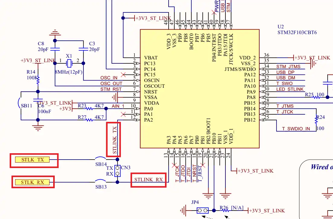
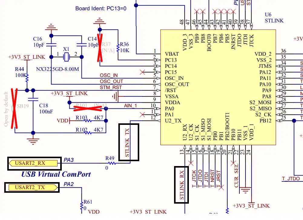
As you can see in the images above, both Nucleo F446RE and Discovery F412 supports the USB Virtual Com Port. So if you are using either of these boards, you do not need to use an additional module to communicate to the computer. The USB used for the ST link can also be used for the communication.
Not all the boards support this Virtual Com port feature. Below is the image from the schematic of the very famous STM32F4 Discovery board.
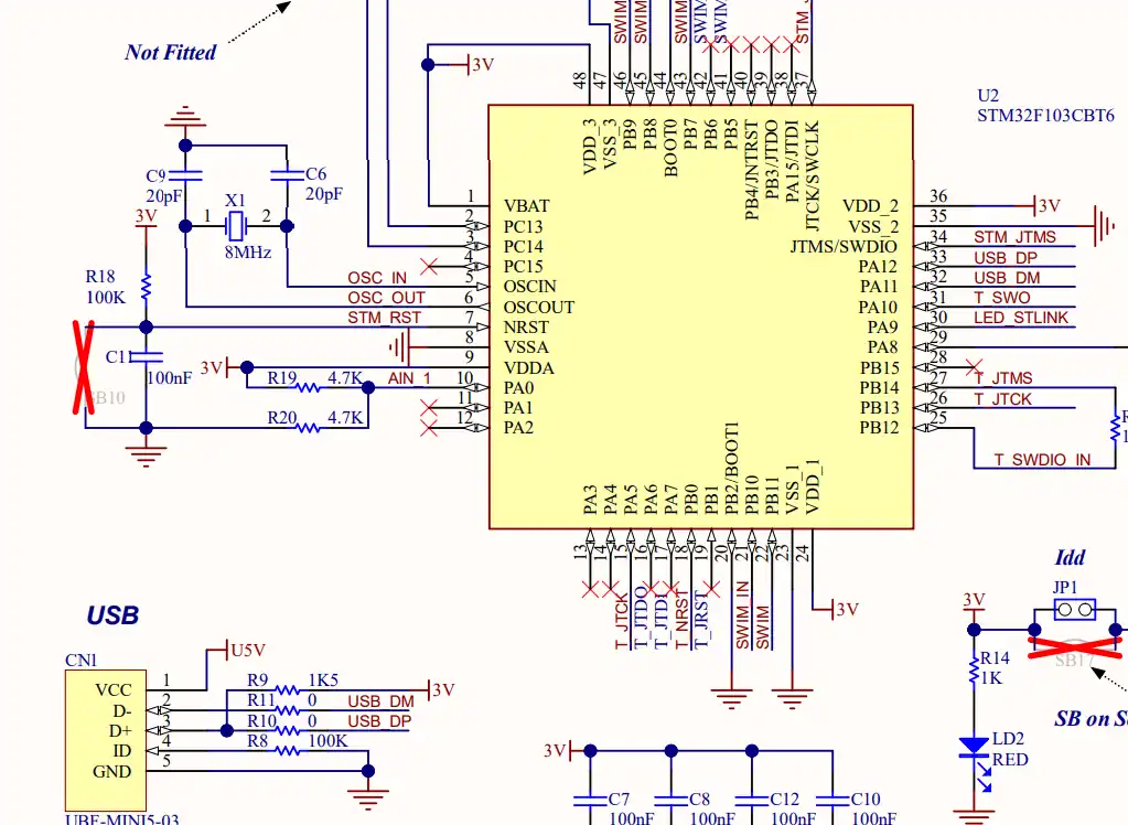
As you can see in the image above, there is no virtual com port in the F4 Discovery board. In such cases we can use some module to convert the UART signals to the USB, which is connected to the computer.
The image below shows the connection between the MCU and the FT232 USB to UART converter.
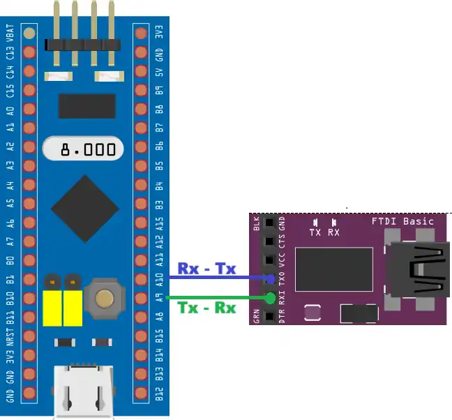
The UART is always connected in the cross connection, connecting the TX pin of the MCU to the RX of the device and the RX to the TX of the device. The module then connects to the computer using the USB.
STM32 CubeMX UART Configuration
The image below shows the UART configuration in CubeMX.
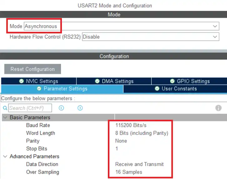
We will use the Asynchronous Mode for the communication. Only 2 pins are used in the Asynchronous mode, TX and RX. The baud rate is set to 115200. We need to use the same baud rate for the receiver device also.
Word length consists of the data bits and the parity bit. STM32 supports different word lengths of 7 bits, 8 bits and 9 bits. A typical UART frame is shown in the image below.
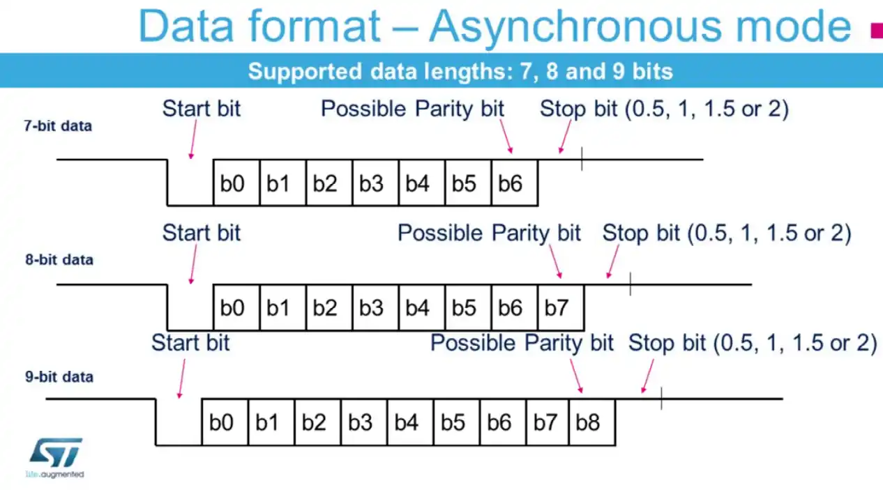
The frame consists of a start bit, data bits and stop bits. we are using 8 data bits with no parity bit and 1 stop bit. We need to use the same configuration in the receiver device also. The data direction is set to Receive and Transmit.
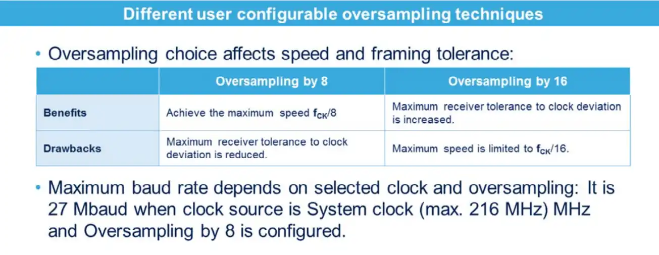
The oversampling is used to increase the tolerance of the receiver to the clock deviation. But it also reduces the maximum baud rate the device can achieve. The image below explains the oversampling and max baud rate.
This is all the configuration we need to do in the cubeMX. Let’s see the code now.
Write Code to Transmit Data via UART
We can only send the ascii characters via the UART. Below we will see how to send a simple string and a number, by converting it to the character format.
Sending string via UART
We can directly send a string via the UART. The code below sends the string every 1 second.
uint8_t data[] = "Hello world\n";
int main()
{
  ....
   while (1)
   {
     HAL_UART_Transmit(&huart2, data, 12, 1000); HAL_Delay(1000);
   }
}Here we define an array (data) which contains the string to be sent to the UART. Then call the function HAL_UART_Transmit in the while loop every 1 second.
The parameters of the function are as follows:
- @UART Instance, huart2
- @pointer to the data array, data
- @size of the data in bytes, 12
- @timout in case of error, 1000ms
Sending number via UART
As I mentioned we can not send the number directly to the UART. It only transmits the data in the ascii format. To send the number, we first need to convert each digit of the number to the character format and then send the data to the UART.
#include <stdio.h>
uint8_t number = 123;
uint8_t numarray[4];
int main()
{
 ....
 while (1)
 {
   sprintf(numarray, "%d\n", number);
   HAL_UART_Transmit(&huart1, numarray, 4, 1000);
   HAL_Delay(1000);
 }
}Here we will send the number 123 to the UART. We first need to define an array of size at least the number of digits of the number.
The sprintf function is used to convert the number to the character format. The format specifier, %d, is used to convert the integral value (123).
After conversion the characters are stored in the array, numarray. We send this array to the UART every 1 second.
Testing STM32 UART Output
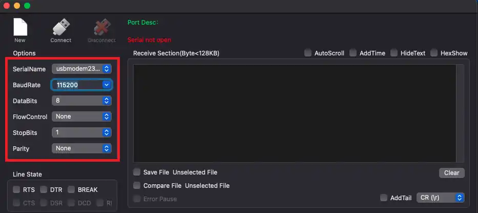
The Serial console on the computer should have the same configuration as we did for the STM32 in the cubeMX. The image below shows the configuration with the baud rate of 115200, 8 data bits with 1 stop bit and no parity.
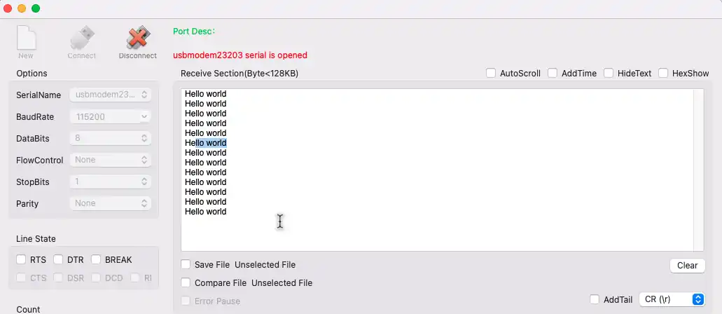
The data sent by the STM32 is received in the serial console. The image below shows the data, “Hello world”, printed several times. It was sent every 1 second by the MCU.
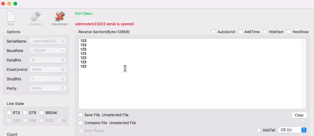
We also sent the number to the UART. The image below shows the number output on the console.
Video Tutorial
STM32 UART Transmit Data Video Tutorial
This tutorial shows how to configure UART on STM32 and transmit data using CubeMX and HAL. Follow the step-by-step guide while watching the video walkthrough to see the setup, coding, and testing in action.
Watch the VideoConclusion
In this tutorial, you learned how to configure STM32 UART transmit data using STM32CubeMX and HAL in blocking mode. We covered UART vs USART, key settings like baud rate, data bits, stop bits, and parity, and explained the pros and cons of blocking mode.
UART is simple, reliable, and perfect for sending strings, numbers, and debug messages. After mastering blocking mode, you can explore interrupt and DMA modes for faster and more efficient communication. This step-by-step approach will help you use STM32 UART in real projects such as IoT, sensors, and data logging.
Browse More STM32 UART Tutorials
STM32 UART Part 3 – Receive Data in Blocking & Interrupt mode
STM32 UART Part 4 – How to Receive Data using UART DMA
STM32 UART Part 4 – Receive Data Using IDLE Line (Interrupt & DMA Methods)
STM32 UART Part 6 – Half-Duplex Communication (Single-Wire Mode)
STM32 UART Part 7 – How to use one-Wire Protocol
STM32 UART Part 8 – LIN Communication Tutorial

“Here is a comparison table between UART and USART based on the information you provided:”
Thanks GPT. Now I know not to use this site ever again. I did have suspicions that it was AI generated but now I’m 100% sure.
Really ? Based on that line you concluded that the post is generated by AI ? Yes that table is AI generated, but didn’t you see “ based on the information you provided:”.
It is easier to generate table with AI by providing the relevant info than typing all the rows and columns by myself.