
Published: March 23, 2026
Last Updated: March 23, 2026
Last Updated: March 23, 2026
Build a Web Server on STM32 using Mongoose – LEDs, PWM and ADC Dashboard
In the previous tutorial, we set up the Mongoose networking library on STM32 and got the basic project running. In this tutorial, we go further and build a working web server that actually controls hardware.
This tutorial will cover how to build a web-based dashboard running on the STM32. From this dashboard, we can toggle two on-board LEDs, control the brightness of an external LED using a PWM slider, and read ADC values displayed on a live gauge.
I am using the STM32H745 Discovery board for this project. The steps should be similar for other STM32 boards that have an Ethernet MAC.
Creating the Web UI with Mongoose Wizard
The first step is to create the web dashboard that will run in the browser. Mongoose provides an online tool called the Mongoose Wizard for this. It lets us design the UI visually and then generates all the frontend code (HTML, CSS, and JavaScript) embedded directly inside the C project. We do not have to write any web code manually.
Let’s go through the setup step by step.
Setting Up a New Project in Mongoose Wizard
Go to mongoose.ws and open the Mongoose Wizard.
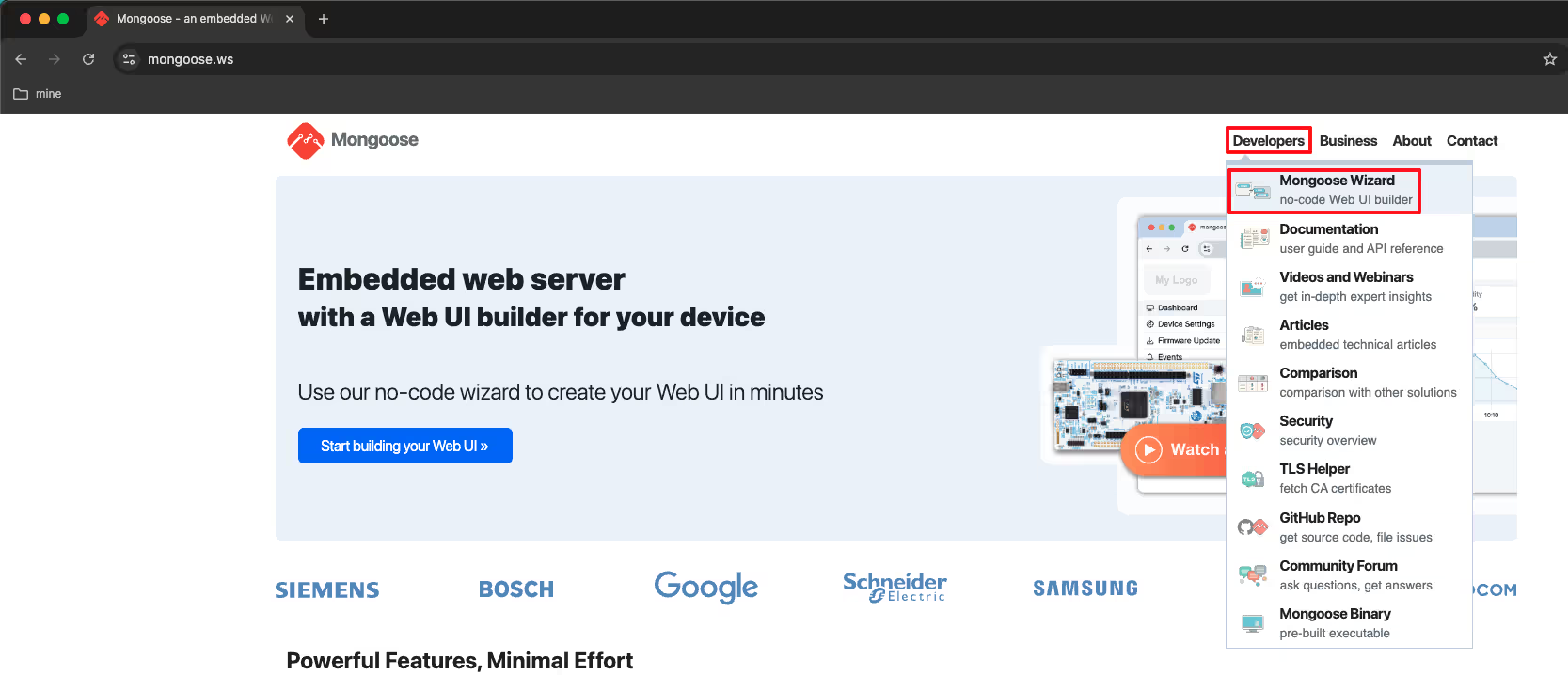
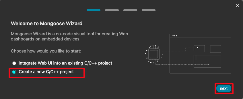
Click on New Project. We are starting fresh here, not integrating into an existing project.
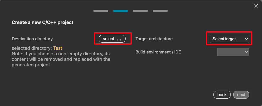
The next screen asks for a destination directory. This is where the generated project files will be saved on your computer. Select a folder and move to the next step.
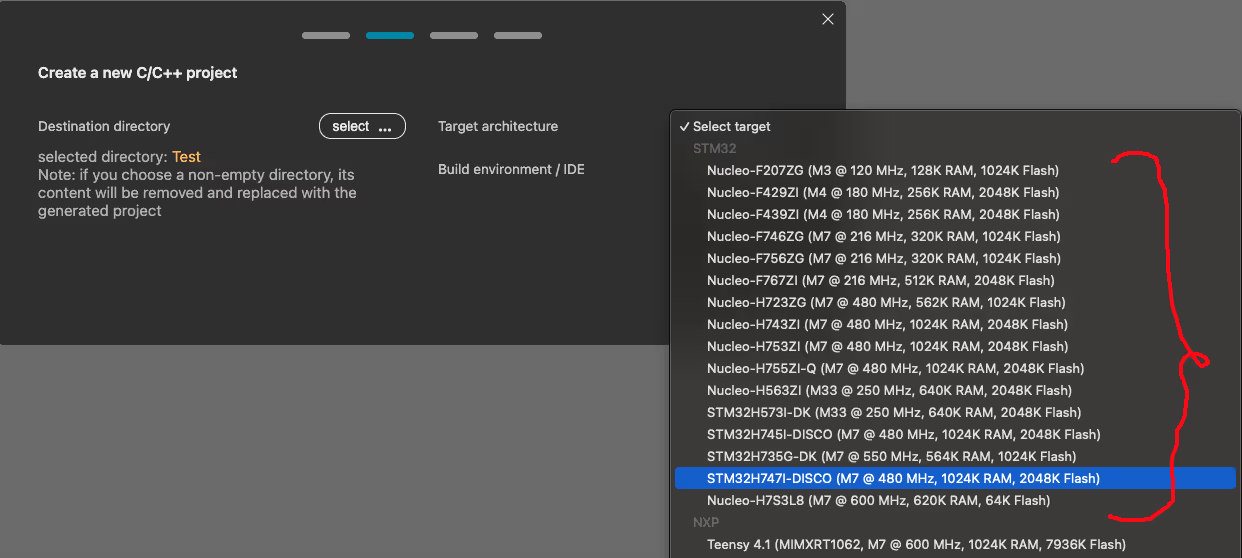
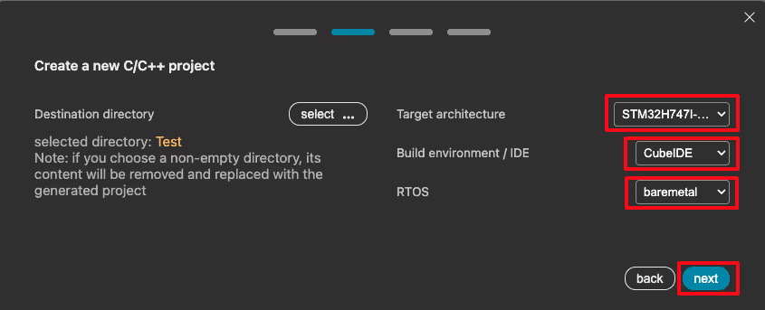
Now we need to select the Target Architecture. Mongoose supports several STM32F and STM32H series boards. I am using the STM32H745 Discovery board, so I selected that from the dropdown.
On the next screen, select the Build Environment and the RTOS. I chose STM32CubeIDE as the IDE and No RTOS since we are keeping things simple for now.
The wizard then asks us to pick a starting dashboard template. I selected the one with a single LED toggle. It gives us something to start with rather than building from a completely blank canvas.
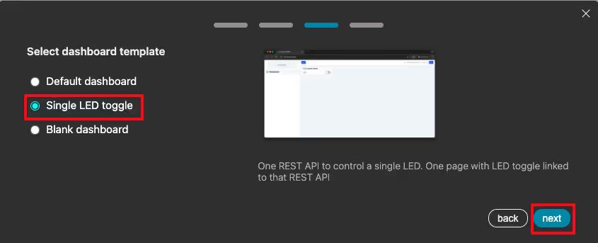
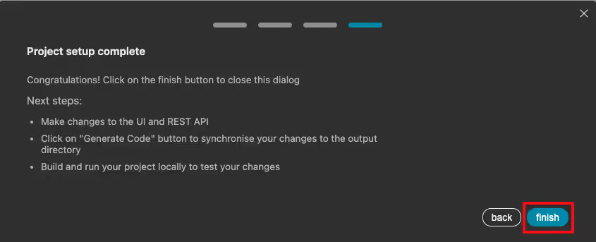
Click Finish. The wizard now opens the web UI editor.
The editor loads the default UI with a single LED toggle button. By default the HTTP and HTTPS listeners are enabled. Also verify the information under Source Code Generator with the configuration we made for the UI.
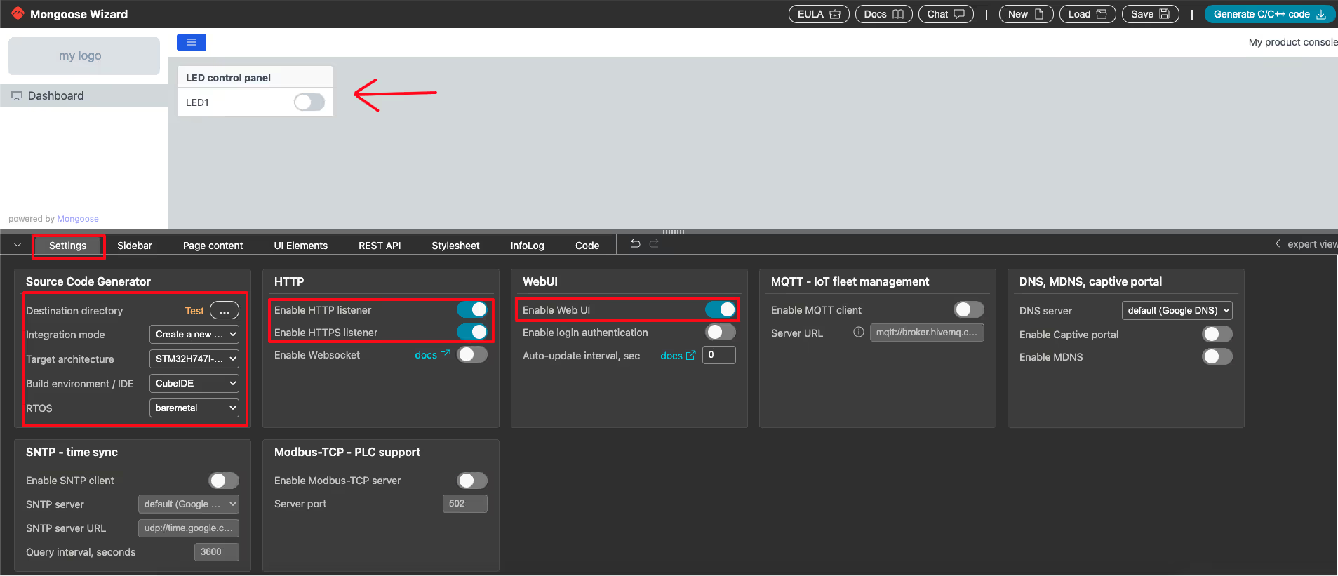
This is the base we will build on. Next, we will add more elements to the dashboard.
Adding UI Elements – Toggle, Slider and Gauge
Here we will add some elements to the UI, which we will later connect with the different components on the STM32 dev board.
The UI Elements panel in the editor shows all the available UI elements. We can see toggles, sliders, gauges, text displays, input fields, and more.
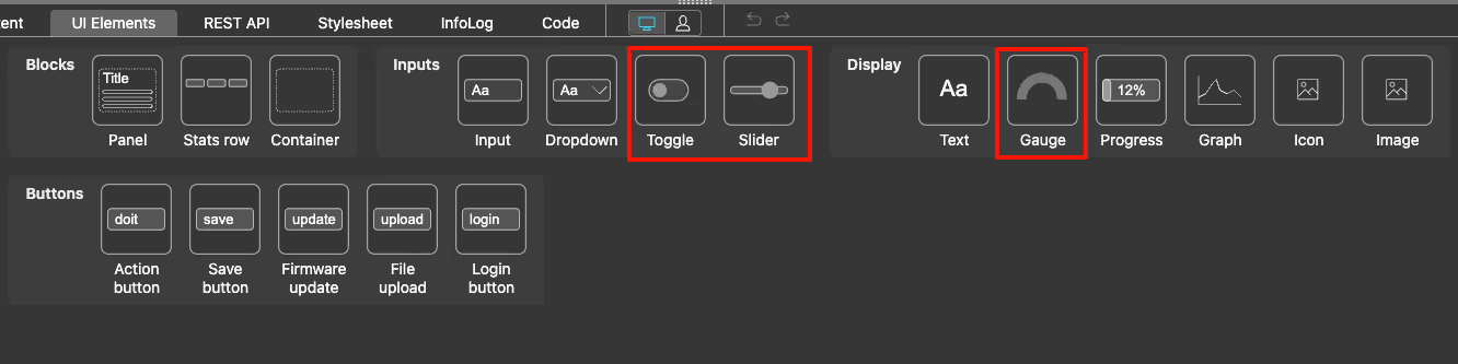
For our project, we need to add three more elements on top of the existing LED toggle:
- A second toggle button to control the second on-board LED
- A slider to control the PWM duty cycle (and therefore the LED brightness)
- A gauge to display the live ADC reading
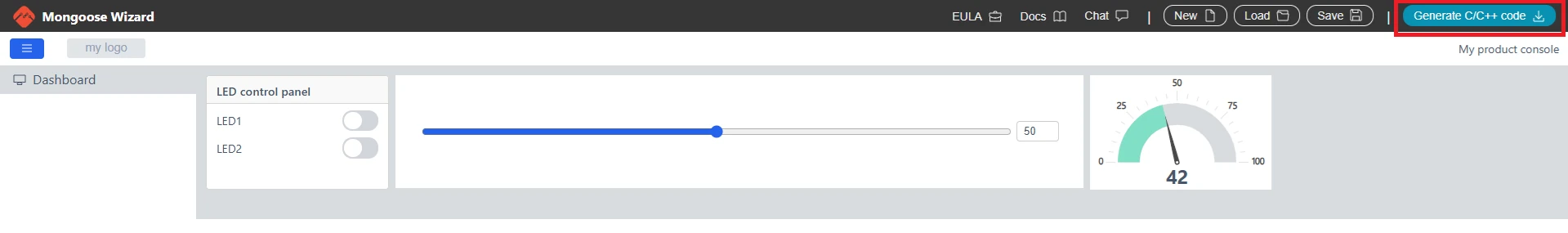
Drag and drop these elements onto the canvas. Once all four elements are placed, the dashboard should look like the image below.
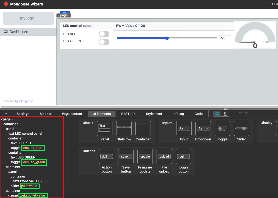
On the left panel, we can see all the elements listed in their hierarchical order. Each element needs to be connected to an API variable so that the web UI can communicate with the C code on the STM32. These API variables are defined in the REST API tab.
We will now configure each element one by one.
Configuring the LED Toggle Element
Click on the REST API tab. We will create an endpoint here for the LED toggles.
I created an endpoint and named it leds. The type is set to data. A data type endpoint maps directly to a C structure in the generated code. Think of it as a struct that holds the current state of the UI element.
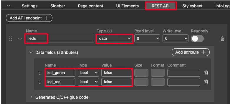
Inside this endpoint, I added two members:
led_red-> type: boolean, default value:falseled_green-> type: boolean, default value:false
Now go back to the Page Content section and click on the first toggle button. In the element settings panel, set the API variable to leds.led_red. Do the same for the second toggle button and set its API variable to leds.led_green.
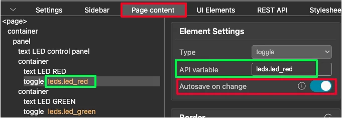
There is one more important setting here — Autosave on change. Make sure this is enabled for both toggle buttons. When this is on, the toggle state is sent to the STM32 immediately the moment it changes. We do not need a separate submit button.
So every time we click a toggle in the browser, the leds structure is updated, and the glue_set_leds function is called on the STM32 side — which we will write in the code section.
Configuring the PWM Slider Element
Back in the REST API tab, I created another endpoint and named it pwm. The type is again set to data.
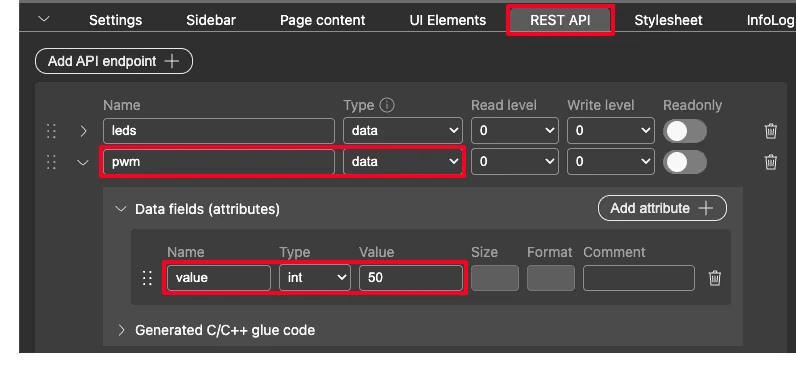
This endpoint has one member:
value— type: integer, default value:50
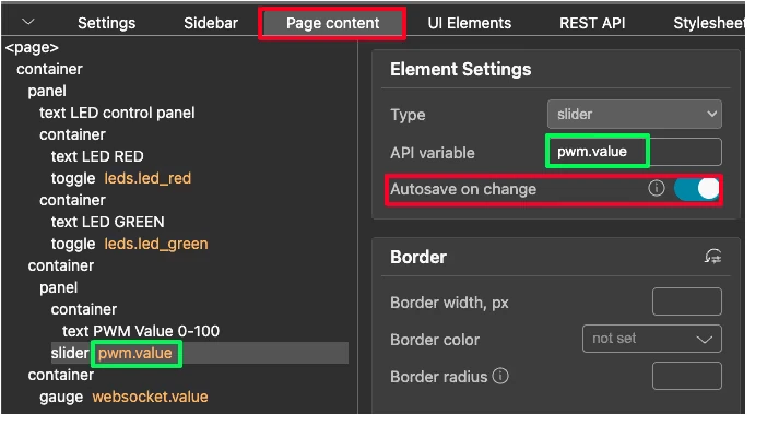
Click on the slider element on the Page Content section. In the settings panel, set the API variable to pwm.value. Also enable Autosave on change here too.
We can also control the range of the slider. In the Element Style (expert view) panel, there are fields for Minimum value, Maximum value, and Increment value.
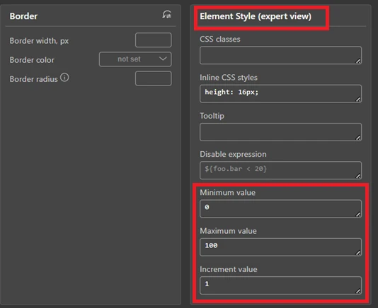
I kept the minimum at 0, maximum at 100, and increment at 1. This means the slider moves in steps of 1, giving us 101 possible values between 0 and 100. We will use this value directly as the PWM duty cycle on the STM32 side. When the user moves the slider, the new value is sent immediately, and the LED brightness updates in real time.
Configuring the ADC Gauge with WebSocket
The gauge is different from the toggle and the slider. Those two send data from the browser to the STM32. The gauge works the other way — it receives data from the STM32 and displays it in the browser.
For this to work, we need the STM32 to periodically push the ADC value to the browser. Mongoose handles this using WebSocket updates.
Go to the REST API tab and create a new endpoint. I named it gauge. Set the type to data.
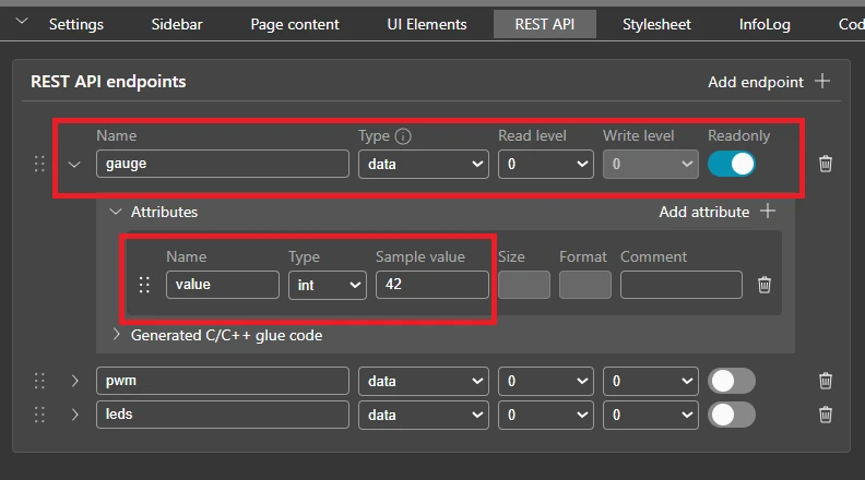
Inside this endpoint, add one attribute under Data fields:
value— type: int, default value:42
Since this endpoint only displays data and the browser never writes to it, make sure to enable the Readonly toggle on the right. This prevents the browser from accidentally sending data back on this endpoint.
Now go to the Page Content section and click on the gauge element. Set its API variable to gauge.value.
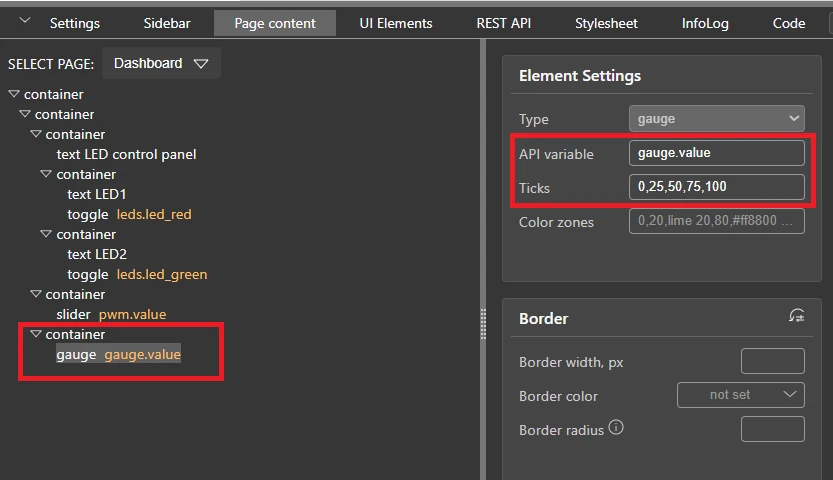
There is also a Ticks field here. This controls the tick marks displayed on the gauge scale. I set it to 0,25,50,75,100, which places a tick at every 25 units. This makes the gauge easier to read at a glance.
There is also a Color zones field. We can use it to color different sections of the gauge — for example, green for low values, orange for mid range, and red for high values. I left this at the default for now, but it is a useful feature if we want to add visual alerts on the dashboard.
With this setup, every time the STM32 sends a WebSocket message containing the gauge.value field, the gauge updates automatically in the browser. We will write the WebSocket callback on the STM32 side in the code section.
Once all elements are configured, click the Generate C/C++ code button.
The wizard generates and downloads the complete project. The folder structure looks like a standard CubeMX project, with one addition — a mongoose folder that contains all the networking, web UI, and glue code.
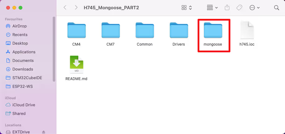
We will load this project in STM32CubeIDE in the next section and configure the peripherals.
Configuring STM32 Peripherals in CubeMX
The generated project folder already has a .ioc file inside it. We load this project in STM32CubeIDE and open the .ioc file to configure the peripherals in CubeMX. We need to set up three things -> the LED GPIO pins, the PWM timer, and the ADC.
LED GPIO Configuration
The STM32H745 Discovery board has two on-board LEDs. Looking at the board schematic:
- LED1 is connected to pin PJ2
- LED2 is connected to pin PI13
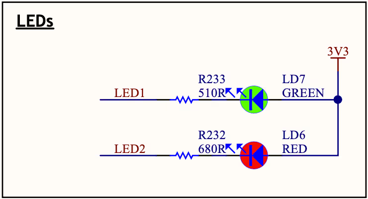
One important thing to note here is how these LEDs are wired. The positive terminals of both LEDs are connected to 3.3V, and the negative terminals are connected to the GPIO pins. This means the logic is inverted:
- Pull the pin LOW to turn the LED ON
- Pull the pin HIGH to turn the LED OFF
We will keep this in mind when writing the GPIO control code later.
In CubeMX, click on pin PJ2 and set it as GPIO_Output. Do the same for PI13.
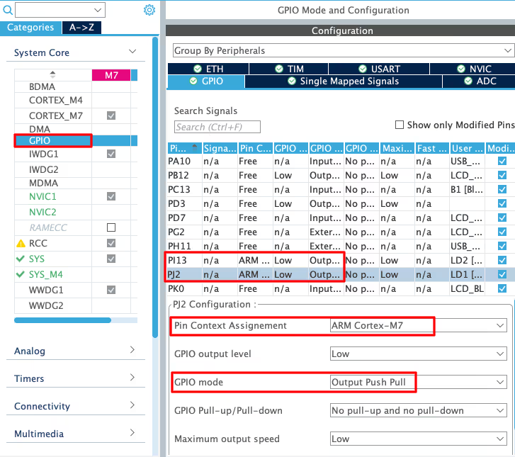
Since the STM32H745 is a dual-core processor (Cortex-M7 and Cortex-M4), we also need to make sure these pins are assigned to the correct core. I am running the project on the CM7 core, so both pins should be assigned to CM7.
PWM Configuration using TIM2
We will use PWM to control the brightness of an external LED. I used TIM2 Channel 4 for this. Connect an LED with a suitable resistor to the corresponding GPIO pin of TIM2 CH4.
In CubeMX, go to Timers -> TIM2. Set Channel 4 to PWM Generation CH4.
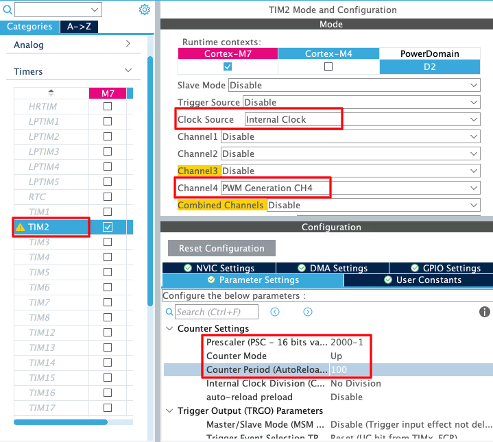
Now set the timer parameters. The key value here is the ARR (Auto Reload Register). Since the slider in the web UI goes from 0 to 100, I set the ARR to 100. This way, the slider value maps directly to the duty cycle — no conversion needed in the code.
The prescaler value does not matter much for LED brightness control. We are not targeting a specific PWM frequency here, so just set a reasonable value. I left it at the default.
ADC Configuration
We will read an analog voltage using ADC1. I used Channel 18 for this in polling mode.
In CubeMX, go to Analog -> ADC1 and enable IN18 Single-ended.
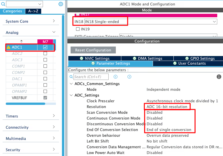
Here are the settings I used:
- Conversion mode: Single conversion
- Continuous conversion: Disabled
- Resolution: 16-bit
We are using polling mode here, which means we will manually trigger the ADC conversion in the code and wait for the result. This keeps things simple and is perfectly fine for a periodic WebSocket update every 200ms.
Once all three peripherals are configured, regenerate the project from CubeMX. We are now ready to write the application code.
Writing the Code in STM32CubeIDE
With the peripherals configured, we now move to the actual code. The generated project already has most of the Mongoose networking code in place. We only need to focus on two files: main.c and mongoose_glue.c.
The mongoose_glue.c file is the bridge between the web UI and the hardware. It contains getter and setter functions for each API endpoint we defined in the wizard. These functions are called automatically by Mongoose whenever the UI state changes. We fill in the hardware control code inside them.
Let’s go through each part one by one.
Controlling LEDs from the Web UI
The generated mongoose_glue.c file already has glue_set_leds and glue_get_leds functions. We could write our code directly inside them, but the problem is that mongoose_glue.c gets overwritten every time the Mongoose Wizard regenerates the project. Any code we wrote inside it will be lost.
The better approach is to define our own getter and setter functions in main.c and register them using mongoose_set_http_handlers. Our code stays safe in main.c and is never touched by the wizard.
We define two functions -> my_get_leds and my_set_leds:
void my_get_leds(struct leds *data) {
  data->led_green = (!HAL_GPIO_ReadPin(GPIOJ, GPIO_PIN_2));
  data->led_red = (!HAL_GPIO_ReadPin(GPIOI, GPIO_PIN_13));
}

void my_set_leds(struct leds *data) {
  HAL_GPIO_WritePin(GPIOJ, GPIO_PIN_2, (!data->led_green));
  HAL_GPIO_WritePin(GPIOI, GPIO_PIN_13, (!data->led_red));
}Since the LEDs are connected in active-LOW mode, we need to invert the logic in both functions. Without the ! operator, the toggle button on the dashboard would show the wrong state — ON when the LED is actually OFF, and vice versa.
In the getter, we invert the pin reading before storing it in data. So when the pin is LOW (LED is ON), data->led_green gets true. When the pin is HIGH (LED is OFF), it gets false. This makes sure the toggle button on the dashboard reflects the actual LED state correctly when the page loads.
In the setter, we invert the incoming value before writing to the pin. So when the user turns the toggle ON (data->led_green = true), we write LOW to the pin to actually turn the LED on. When the toggle is turned OFF, we write HIGH.
Now we register both functions inside main(). This must be called after mongoose_init():
mongoose_init();
mongoose_set_http_handlers("leds", my_get_leds, my_set_leds);
for (;;) {
mongoose_poll();
}The first argument is the API endpoint name. This must match the endpoint name as Mongoose internally references it. The second argument is our getter and the third is our setter.
From this point, Mongoose handles everything automatically. When the page loads, it calls my_get_leds to get the current LED state. When a toggle is clicked, it calls my_set_leds to apply the change. We never have to touch mongoose_glue.c.
Controlling PWM from the Web UI
For PWM control, we follow the same approach as the LEDs. We define our own getter and setter functions in main.c instead of modifying mongoose_glue.c.
We need to start the PWM output first inside main() before anything else:
HAL_TIM_PWM_Start(&htim2, TIM_CHANNEL_4);Now we define the getter and setter functions:
void my_get_pwm(struct pwm *data) {
data->value = TIM2->CCR4;
}
void my_set_pwm(struct pwm *data) {
TIM2->CCR4 = data->value;
}The getter reads the current value from the CCR4 register of TIM2 and stores it in data->value. This makes sure the slider on the dashboard loads at the correct position when the page first opens.
The setter does the opposite. It takes the incoming slider value from the dashboard and writes it directly to CCR4. Since we set the ARR to 100 in CubeMX, writing any value between 0 and 100 here directly sets the duty cycle percentage. No conversion is needed.
We then register both functions in main() after mongoose_init(), alongside the LED handlers we registered earlier:
HAL_TIM_PWM_Start(&htim2, TIM_CHANNEL_4);
mongoose_init();
mongoose_set_http_handlers("leds", my_get_leds, my_set_leds);
mongoose_set_http_handlers("pwm", my_get_pwm, my_set_pwm);
for (;;) {
mongoose_poll();
}When the page loads, my_get_pwm is called and the slider snaps to the current duty cycle position. When the user moves the slider, my_set_pwm is called and the LED brightness updates instantly.
Sending ADC Values to the Gauge using WebSocket
The gauge works differently from the LED and PWM handlers. Instead of a setter, we only need a getter, because the browser never sends data to the gauge, it only receives it.
Reading the ADC and sending the value to the gauge involves two steps — reading the value and pushing it over WebSocket periodically.
First, we write the map function and the readADC function in main.c. The map function scales the raw 16-bit ADC value (0 to 65535) down to 0 to 100, matching the gauge scale on the dashboard.
long map(long x, long in_min, long in_max, long out_min, long out_max) {
return (x - in_min) * (out_max - out_min + 1) / (in_max - in_min + 1) + out_min;
}
int readADC(void) {
HAL_ADC_Start(&hadc1);
HAL_ADC_PollForConversion(&hadc1, 100);
uint16_t ADC_VAL = HAL_ADC_GetValue(&hadc1);
HAL_ADC_Stop(&hadc1);
int val = map(ADC_VAL, 0, 65535, 0, 100);
return val;
}Next, we write the getter function for the gauge. It calls readADC() and stores the result in data->value:
void my_get_gauge(struct gauge *data) {
data->value = readADC();
}Now we register this getter in main() after mongoose_init(). Since the gauge is read-only, we pass NULL as the setter. We also call mongoose_add_ws_reporter to tell Mongoose to push the gauge value to the browser periodically:
mongoose_init();
mongoose_set_http_handlers("leds", my_get_leds, my_set_leds);
mongoose_set_http_handlers("pwm", my_get_pwm, my_set_pwm);
mongoose_set_http_handlers("gauge", my_get_gauge, NULL);
mongoose_add_ws_reporter(200, "gauge");
for (;;) {
mongoose_poll();
}mongoose_add_ws_reporter takes two arguments: the interval in milliseconds and the endpoint name.
I set it to 200ms, so the gauge refreshes 5 times per second. Every 200ms, Mongoose calls my_get_gauge internally, fetches the latest ADC value, and pushes it to all connected browser clients automatically.
We do not need to write a WebSocket callback manually like before — mongoose_add_ws_reporter handles all of that for us.
Complete Code
Here is the complete main.c with everything put together:
/*** Map Function ***/
long map(long x, long in_min, long in_max, long out_min, long out_max) {
return (x - in_min) * (out_max - out_min + 1) / (in_max - in_min + 1) + out_min;
}
/*** ADC Functions ***/
int readADC(void) {
HAL_ADC_Start(&hadc1);
HAL_ADC_PollForConversion(&hadc1, 100);
uint16_t ADC_VAL = HAL_ADC_GetValue(&hadc1);
HAL_ADC_Stop(&hadc1);
int val = map(ADC_VAL, 0, 65535, 0, 100);
return val;
}
void my_get_gauge(struct gauge *data) {
data->value = readADC();
}
/*** LED Functions ***/
void my_get_leds(struct leds *data) {
  data->led_green = (!HAL_GPIO_ReadPin(GPIOJ, GPIO_PIN_2));
  data->led_red = (!HAL_GPIO_ReadPin(GPIOI, GPIO_PIN_13));
}

void my_set_leds(struct leds *data) {
  HAL_GPIO_WritePin(GPIOJ, GPIO_PIN_2, (!data->led_green));
  HAL_GPIO_WritePin(GPIOI, GPIO_PIN_13, (!data->led_red));
}
/*** PWM Functions ***/
void my_get_pwm(struct pwm *data) {
  data->value = TIM2->CCR4;
}

void my_set_pwm(struct pwm *data) {
  TIM2->CCR4 = data->value;
}
/*** Main Function ***/
int main(void) {
HAL_Init();
SystemClock_Config();
MX_GPIO_Init();
MX_ADC1_Init();
MX_TIM2_Init();
HAL_TIM_PWM_Start(&htim2, TIM_CHANNEL_4);
mongoose_init();
mongoose_set_http_handlers("leds", my_get_leds, my_set_leds);
mongoose_set_http_handlers("pwm", my_get_pwm, my_set_pwm);
mongoose_set_http_handlers("gauge", my_get_gauge, NULL);
mongoose_add_ws_reporter(200, "gauge");
for (;;) {
  mongoose_poll();
}
}All the code lives in main.c. We do not touch mongoose_glue.c at all.
- The LED and PWM sections each have a getter and setter that handle the two-way communication with the dashboard.
- The ADC section only has a getter since the gauge is read-only —
mongoose_add_ws_reportertakes care of pushing the value to the browser every 200ms. - The
mongoose_poll()loop at the end keeps the entire Mongoose stack running.
Testing the Web Server
Once the code is compiled and flashed to the board, open a browser and navigate to the IP address of the STM32. The dashboard should load with all three controls visible: the two LED toggles, the PWM slider, and the ADC gauge.
LED Output
Click on the LED1 toggle on the dashboard. The toggle should switch state and the corresponding on-board LED should turn on or off immediately. Do the same for LED2.
The GIF below shows the LED toggles working on the dashboard. Clicking the toggle in the browser turns the corresponding on-board LED on and off in real time.
PWM Output
Move the PWM slider on the dashboard. The brightness of the external LED connected to TIM2 Channel 4 should change as the slider moves.
The GIF below shows the PWM slider at different positions and the corresponding change in brightness of the external LED.
At 0, the LED is fully off. At 100, it is at full brightness. Any value in between gives a proportional brightness level. Just like the LED toggles, when the page loads the slider also snaps to the current duty cycle value read from the CCR4 register.
ADC Output
The ADC gauge updates automatically every 200ms without any user interaction. As the analog voltage on ADC1 Channel 18 changes, the gauge needle moves to reflect the new value.
The GIF below shows the ADC gauge updating live on the dashboard as the analog input voltage changes on the STM32H745 board.
Video Tutorial
STM32 Web Server over Ethernet using Mongoose — Part 2 Video Tutorial
Watch the complete walkthrough of this tutorial — designing the web dashboard in Mongoose Wizard, configuring GPIO, PWM and ADC in CubeMX, writing the getter and setter functions in main.c, and testing the live web server that controls LEDs, PWM brightness and displays ADC readings from a browser.
Watch the STM32 Web Server with Mongoose TutorialConclusion
In this tutorial, we built a fully working web server on the STM32H745 Discovery board using the Mongoose networking library. We designed the dashboard in the Mongoose Wizard, configured the GPIO, PWM, and ADC peripherals in CubeMX, and wrote all the hardware control code in main.c using custom getter and setter functions.
This is a solid foundation for building real-world embedded web interfaces. From here, we can add more sensors, more controls, or even authentication — all without changing the overall structure of the project.
More STM32 Mongoose TCP/IP Tutorials
STM32 Mongoose Project Download
STM32 Mongoose TCP/IP FAQs
Subscribe
Login
0 Comments
Newest
