
Home ▸ STM32 Tutorials ▸
STM32 Custom Bootloader Tutorial: Flash Layout and Jump to Application
This is the first tutorial in the series covering custom bootloader for STM32 microcontrollers. This part focuses on the complete setup process, starting from project creation in CubeMX and ending with a successful jump from bootloader to application.
We will create two separate projects: one for the bootloader and one for the application. We will configure peripherals, divide flash memory correctly, write the jump logic, and verify everything on real hardware.
By the end of this post, you will have:
- A working STM32 bootloader
- A correctly relocated application
- Separate binary files for bootloader and application
- Verified execution flow on the target board
Introduction to STM32 Custom Bootloader
A bootloader is the first piece of code that runs when an STM32 microcontroller powers up or resets. Its main job is to decide what should run next. This could be the main application, a firmware update process, or a recovery mode.
Using a custom STM32 bootloader gives you much more control than relying on the default system bootloader. It allows you to manage how your firmware starts, how updates are handled, and how errors are detected.
One of the biggest reasons to use a custom bootloader is firmware updates. With a bootloader in place, you can update the application without using a debugger. This is essential for OTA updates, remote devices, and products deployed in the field.
A custom bootloader also improves system reliability. It can verify the application before running it. If the application is missing or corrupted, the bootloader can stop the jump and prevent the system from crashing.
Another key benefit is memory control. The bootloader defines clear boundaries between itself and the application. This prevents accidental overwrites and makes flash management safer and more predictable.
Custom bootloaders also help during development and debugging. You can add logs, status LEDs, and fallback logic. This makes it easier to understand what the system is doing during startup.
A custom STM32 bootloader gives you:
- Safe and controlled firmware startup
- Support for OTA and remote updates
- Application validation and protection
- Better flash memory management
- More flexibility for future features
Tools and Software Required
Before we start building the bootloader and application, we need to make sure the required tools and software are ready. Using the correct tools helps avoid setup issues and keeps the workflow smooth.
In this tutorial, we will use STM32 official tools along with basic hardware. The versions mentioned here are tested and work well with this setup.
STM32CubeIDE and CubeMX Version
We will use STM32CubeIDE as the main development environment. It is used for writing code, building projects, and debugging.
In recent versions of STM32CubeIDE, CubeMX is no longer integrated inside the IDE. Because of this, we need a separate installation of STM32CubeMX to create projects. Make sure both tools are installed and up to date. The exact version is not critical, but using a recent stable release is recommended.
STM32CubeMX will be used to:
- Select the MCU
- Configure clocks and peripherals
- Generate projects for STM32CubeIDE
STM32CubeIDE will be used to:
- Write bootloader and application code
- Modify linker scripts
- Build binary files
STM32CubeProgrammer
CubeProgrammer is used to flash the generated binary files into the STM32 microcontroller.
We will use it to:
- Flash the bootloader binary
- Flash the application binary
- Program specific flash addresses
This tool makes flashing easier, especially when working with separate bootloader and application binaries. Make sure STM32CubeProgrammer is installed and the ST-Link drivers are working correctly.
Hardware Used for Testing
For hardware testing, we will use a Bluepill board based on the STM32F103C8 microcontroller.
The following hardware is required:
- STM32 Dev board (STM32F103/STM32F446 are the main focus)
- ST-Link programmer
- USB-to-UART converter
- Two LEDs with resistors
- Jumper wires
One LED is used to indicate bootloader status, and the other LED is used to indicate application execution. UART is used to view log messages during bootloader and application startup.
Creating the STM32 Bootloader Project in CubeMX
The bootloader must always be created before the application. This is because the bootloader defines the flash memory layout and controls how the system starts after reset. By setting up the bootloader project first, we make sure that the application fits correctly into the remaining flash memory. This also avoids address conflicts and makes future updates safer.
In this section, we will create a minimal bootloader project using STM32CubeMX. We will only enable what is required. Extra features can be added later if needed.
Enabling Minimum Required Peripherals
A bootloader should be lightweight and simple. We only enable peripherals that are needed for:
- Debugging
- Status indication
- Logging
Avoid enabling unused peripherals. This keeps the bootloader small and reduces flash usage.
For now, we will enable only GPIO, UART, and SYS.
Enabling Serial Wire Debug (SWD)
Go to the SYS configuration and enable Serial Wire Debug (SWD) mode.
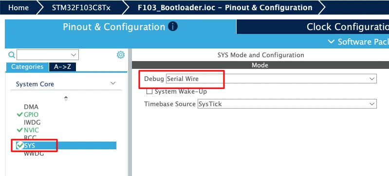
This allows you to:
- Debug the bootloader code
- Set breakpoints
- Inspect registers and memory
SWD is very helpful during development and troubleshooting.
Configuring GPIO for Bootloader Status LED
To visually confirm bootloader behavior, we will use an LED. Configure pin PA4 as a GPIO Output.
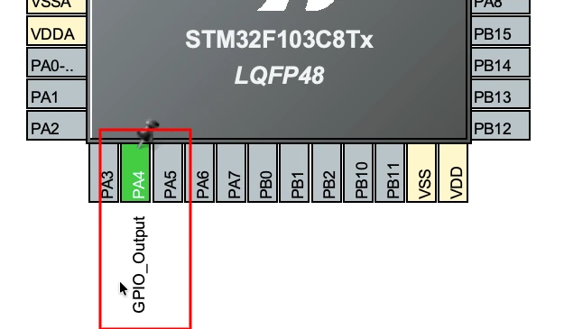
This LED will be used to:
- Indicate bootloader activity
- Signal failure cases, such as a jump error
Using an LED makes debugging easier, especially when UART is not available.
Enabling UART for Bootloader Logs
Next, enable USART1 in CubeMX. Set it in Asynchronous mode.
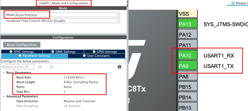
UART will be used to print log messages from the bootloader. These logs help confirm the execution flow during startup. Make sure the TX pin is correctly mapped to the MCU pin used on your board.
Generating Bootloader Project for STM32CubeIDE
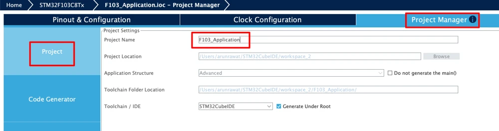
Once all required peripherals are configured, go to the Project Manager tab. Enter a suitable name for the bootloader project. Select STM32CubeIDE as the target IDE. Finally, click Generate Code to create the project.
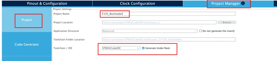
The bootloader project is now ready and can be imported into STM32CubeIDE for further development.
STM32 Bootloader Flash Memory Layout
After importing the project to STM32CubeIDE, we will first start with defining the flash layout for this entire project. To keep the bootloader and application in sync, we must define the flash memory layout in one common place. This avoids hardcoding addresses in multiple files and prevents mismatches between projects.
A shared flash layout makes the system easier to maintain and safer to update. If the memory layout ever changes, we only need to update it in one file.
The flash layout decides where the bootloader lives, where the application starts, and which areas can be safely erased. This is especially important when working with firmware updates and OTA mechanisms.
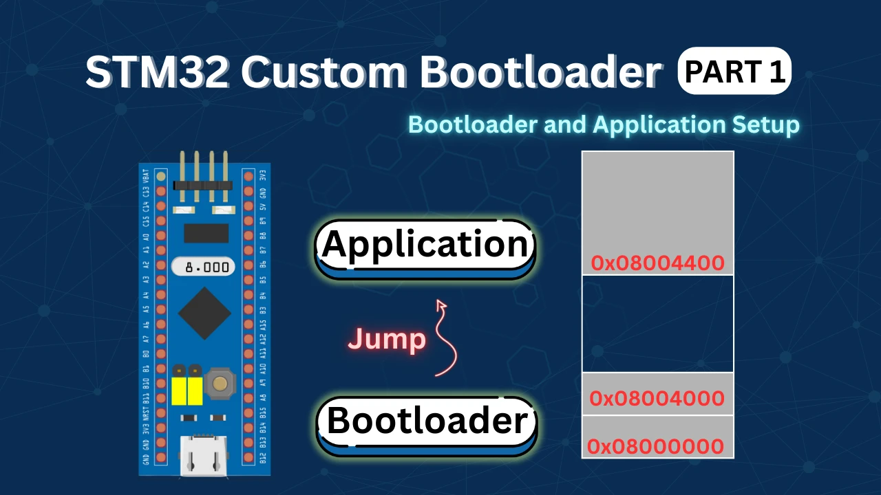
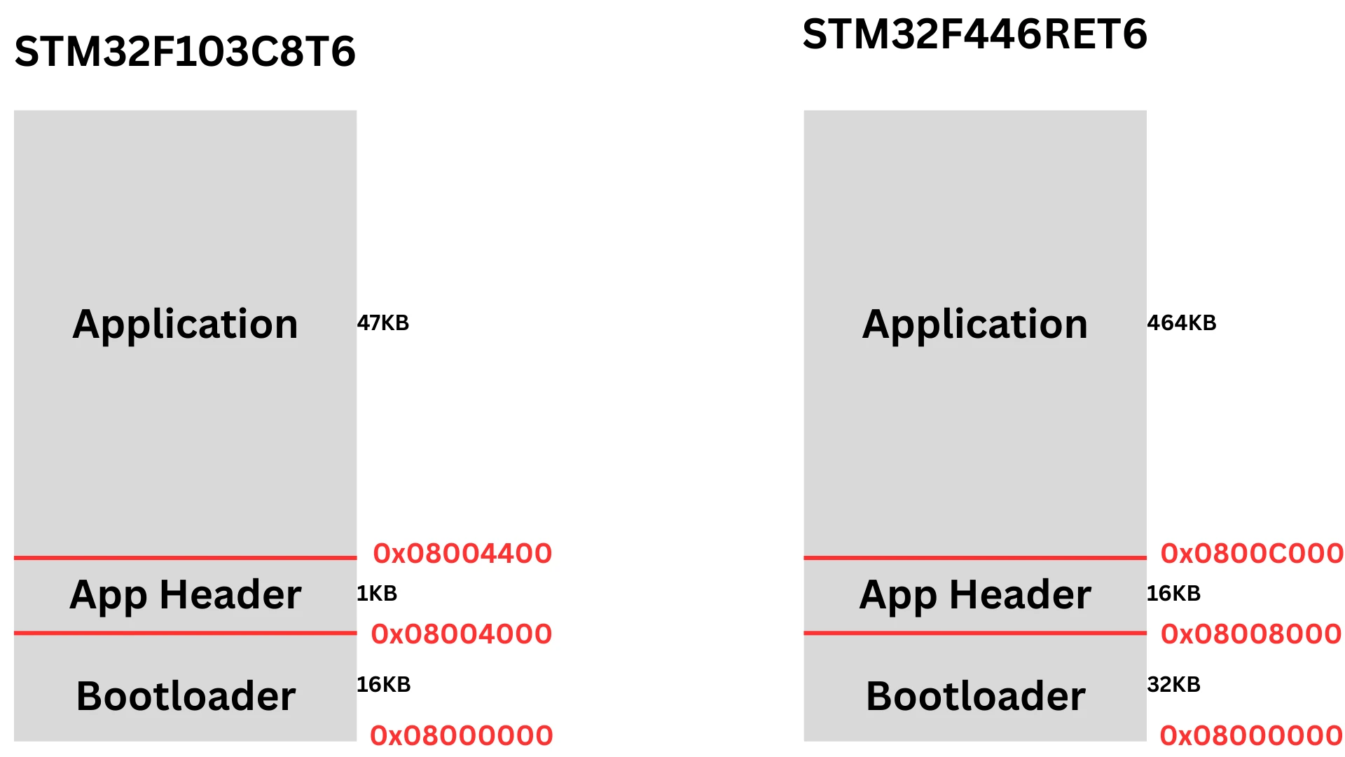
In this tutorial, the flash memory is divided into three fixed regions. Each region has a specific role and must not overlap with the others.
Defining Bootloader and Application Addresses
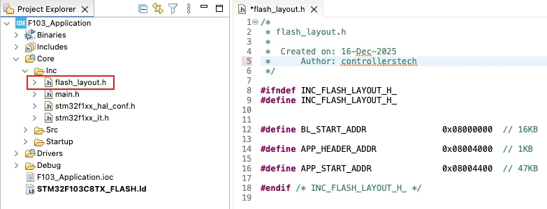
Create a new header file named flash_layout.h inside the bootloader project. This file will contain all the flash address definitions.
#define BL_START_ADDR        0x08000000  // 16KB
#define APP_HEADER_ADDR      0x08004000  // 1KB
#define APP_START_ADDR 0x08004400 // 47KBEach macro clearly defines the start address of a flash region.
BL_START_ADDRpoints to the bootloader startAPP_HEADER_ADDRpoints to the application headerAPP_START_ADDRpoints to the application code
Using named macros makes the code more readable and easier to debug.
Sharing Flash Layout Between Bootloader and Application
The same flash layout must be used by both the bootloader and the application. We will copy the flash_layout.h file into the application project as well.
This ensures:
- Both projects use the same memory map
- The jump address is always correct
- Flash erase operations stay safe
Inside both projects, include this header file wherever flash addresses are required. By sharing a single flash layout definition, we make the bootloader design more robust.
Modifying Linker Script for Bootloader
By default, the bootloader project can access the entire flash memory of the microcontroller. This is dangerous because the bootloader could accidentally overwrite the application area.
To prevent this, we must restrict the bootloader’s flash usage. This is done by modifying the linker script. Once restricted, the linker will ensure that the bootloader code fits only inside its allocated flash region.
Limiting Bootloader Flash to 16 KB
Open the linker script file of the bootloader project. This file usually ends with .ld.
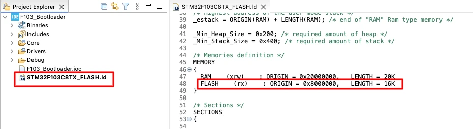
Locate the FLASH memory definition section and change the flash length so that it matches the bootloader size.
FLASH (rx) : ORIGIN = 0x08000000, LENGTH = 16KThis tells the linker that the bootloader can only use 16 KB of flash memory. If the bootloader code exceeds this limit, the build will fail. This is a good safety check.
Implementing Bootloader Jump to Application
After setting up the flash layout, the most important task of the bootloader is to transfer control to the application. This process is called a bootloader jump.
In this section, we will implement a safe and reliable bootloader-to-application jump mechanism.
Creating Bootloader Jump Source and Header Files
To keep the code clean, we will place all jump-related logic in separate files. Create two new files in the bootloader project:
bl_jump.cbl_jump.h
These files will contain the functions used by the bootloader to jump to the application. Separating this logic makes the code easier to read and maintain.
Understanding JumpToApplication Function
The core of the jump mechanism is the JumpToApplication() function.
typedef void (*pFunction)(void);

void JumpToApplication(void)
{
    uint32_t appStack;
    uint32_t appResetHandler;
    pFunction appEntry;

    /* Read application stack pointer */
    appStack = *(volatile uint32_t*)APP_START_ADDR;

    /* Read reset handler address */
    appResetHandler = *(volatile uint32_t*)(APP_START_ADDR + 4);
    appEntry = (pFunction)appResetHandler;

    /* Disable interrupts */
    __disable_irq();

    /* Stop SysTick */
    SysTick->CTRL = 0;
    SysTick->LOAD = 0;
    SysTick->VAL  = 0;

    /* Set main stack pointer */
    __set_MSP(appStack);

    /* Jump to application reset handler */
    appEntry();
}Every Cortex-M application starts with a vector table.
- The first 4 bytes contain the initial stack pointer
- The next 4 bytes contain the reset handler address
The bootloader reads both values directly from the application flash.
Disabling Interrupts and SysTick
Before jumping to the application, the bootloader must clean up its runtime environment.
    /* Disable interrupts */
    __disable_irq();

    /* Stop SysTick */
    SysTick->CTRL = 0;
    SysTick->LOAD = 0;
SysTick->VAL = 0;- First, all interrupts are disabled.
This prevents bootloader interrupts from firing while the application is running. - Next, the SysTick timer is completely stopped.
SysTick may have been configured by the bootloader. The application expects a fresh start, so SysTick must be cleared.
This step avoids unexpected timer interrupts after the jump.
Setting MSP and Jumping to Reset Handler
After cleanup, the bootloader sets the Main Stack Pointer (MSP) using the value read from the application vector table, __set_MSP(appStack).
This step is mandatory for Cortex-M cores.
Finally, the bootloader jumps to the application reset handler, appEntry().
At this point:
- Bootloader code stops executing
- Application startup code begins
- Control is fully transferred
The application now runs exactly as if it was started after a hardware reset.
Generating Bootloader Binary File
Once the bootloader project is complete, the next step is to generate a binary file.
Enabling Binary Output for Bootloader
Right-click on the project and select Properties. Go to C/C++ Build → Settings → Post-build outputs.
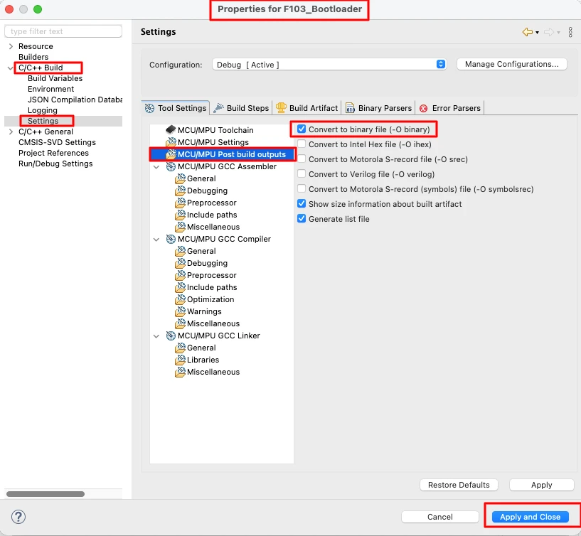
Enable the option to generate a binary file. Apply the changes and build the project again. After a successful build, the bootloader binary file will be created automatically.
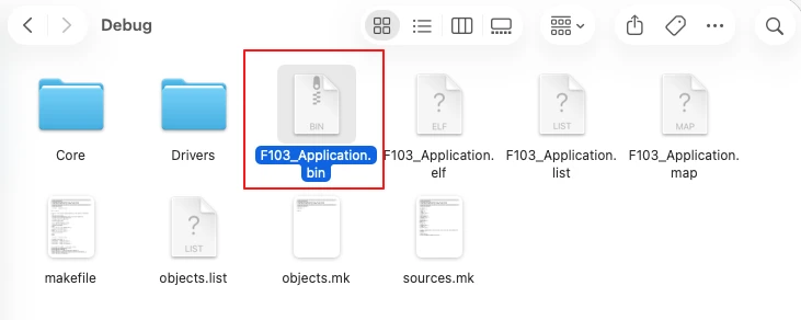
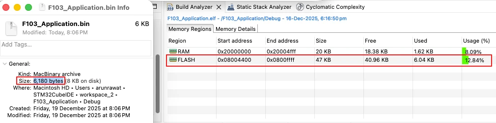
Verifying Bootloader BIN Size
Once the build completes, navigate to the Debug folder inside the application project directory. Here, you should find the generated bootloader.bin file.
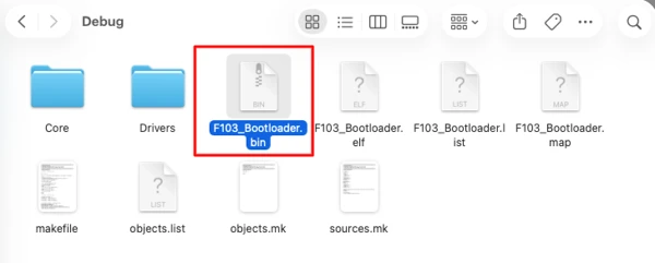
Check the file size and compare it with the flash usage shown in the memory view. The binary size should match the reported flash usage.
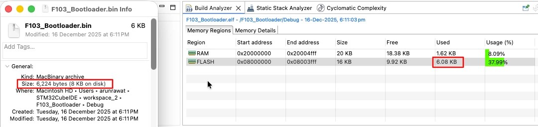
This confirms that the bootloader is built correctly and the binary is ready to be flashed.
Creating STM32 Application Project in CubeMX
After completing the bootloader, the next step is to create the application project. Unlike the bootloader, the application is a full-featured firmware. It can use more peripherals, run complex logic, and handle updates.
This project will live in a separate flash region, and the bootloader will jump to it after reset.
Configuring System Clock
Create a new project in STM32CubeMX and go to the Clock Configuration tab.
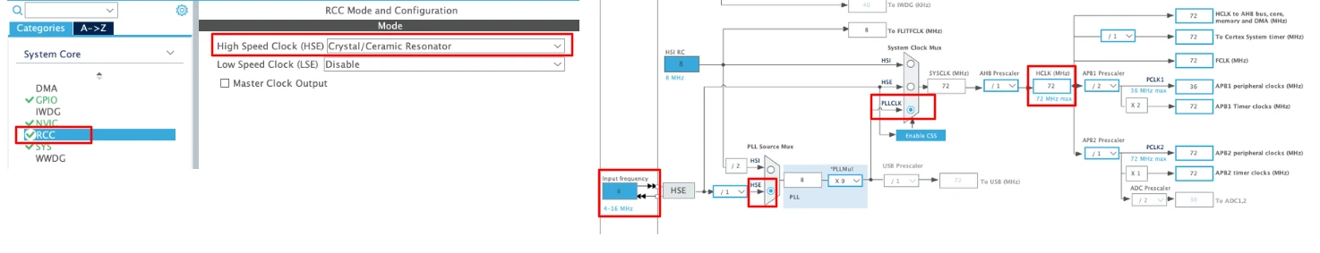
Enable the external crystal (HSE). Also set the system clock to 72 MHz, which is the maximum frequency supported by STM32F103.
Enabling Serial Wire Debug (SWD)
Go to the SYS configuration and enable Serial Wire Debug (SWD) mode.
This allows you to:
- Debug the bootloader code
- Set breakpoints
- Inspect registers and memory
SWD is very helpful during development and troubleshooting.
Configuring GPIO for Application LED
To visually confirm Application behavior, we will use an LED. Configure pin PA1 as a GPIO Output.
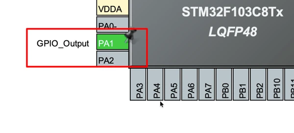
This LED will be used to indicate the successful application execution.
Enabling UART for Application Logs
Next, enable USART1 in CubeMX. Set it in Asynchronous mode.
UART will be used to print log messages from the application. These logs help confirm the execution flow during startup. Make sure the TX pin is correctly mapped to the MCU pin used on your board.
Generating Application Project for STM32CubeIDE
Once all required peripherals are configured, go to the Project Manager tab. Enter a suitable name for the application project. Select STM32CubeIDE as the target IDE. Finally, click Generate Code to create the project.
Modifying Application Linker Script and Vector Table
Since the application does not start at the beginning of flash memory, we must relocate it properly. This step ensures the STM32 knows where the application code and interrupt vectors are stored.
Setting Application Flash Start Address
Open the application linker script inside STM32CubeIDE.
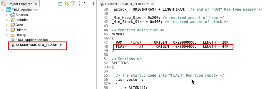
Locate the FLASH memory definition section and change the flash ORIGIN and LENGTH so that it matches the application size.
FLASH (rx) : ORIGIN = 0x08004400, LENGTH = 47KThis tells the linker that the application flash region starts from 0x08004400 and can only use 47 KB of flash memory.
Relocating Vector Table (VTOR)
Now copy the flash_layout.h file we created in the bootloader project, to the application project as well.
Because the application does not start at 0x08000000, the vector table must be relocated. Also the bootloader disables all interrupts before jumping to the application, so inside the application, interrupts must be enabled again.
We should do this inside the main() function. Place the code after HAL initialization and before system clock configuration.
  /* Reset of all peripherals, Initializes the Flash interface and the Systick. */
  HAL_Init();

  /* USER CODE BEGIN Init */

  SCB->VTOR = APP_START_ADDR;   // Add This
  __enable_irq();   // Add This

  /* USER CODE END Init */

  /* Configure the system clock */
SystemClock_Config();This ensures:
- Interrupts point to the correct handlers
- The reset handler works as expected
This completes the transition from bootloader to application. The application is now ready to run normally with full interrupt support.
Generating Application Binary File
Just like we did for the bootloader, the next step is to generate a binary file for the application. This binary will be flashed into the MCU after the bootloader, so it must be verified for size and location.
Similar to the bootloader, enable the post-build option to generate a binary file.
After building the project, the .bin file will be created automatically.
Verifying Application BIN Size
Navigate to the Debug folder to locate the application binary.
Compare the binary size with the flash usage in the memory view to ensure it matches the flash usage shown in the memory view.
This confirms that the application is ready to be flashed alongside the bootloader.
Flashing Bootloader and Application Using STM32CubeProgrammer
Once both the bootloader and application binaries are ready, the next step is to flash them onto the STM32 microcontroller. The flashing order is important: the bootloader must be flashed first, followed by the application. This ensures that the bootloader is in control and can safely jump to the application after reset.
We will use STM32CubeProgrammer to program both binaries into their respective flash regions.
Flashing Bootloader Binary
- Connect the ST-Link programmer to your STM32 board.
- Open STM32CubeProgrammer and go to the Download section.
- Set the flash address to the start of flash memory (
0x08000000). - Browse and select the bootloader binary generated earlier.
- Double-check the address and click Start Programming.
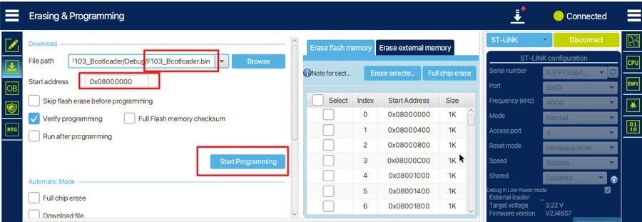
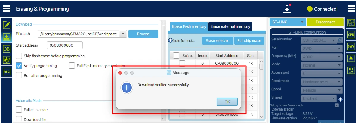
Output
The image below shows the bootloader binary successfully flashed at the start of flash memory.
Flashing Application Binary
After flashing the bootloader, locate the application binary in the debug folder.
- Set the flash address to the application start address (
0x08004400). - Click Start Programming to flash the application binary.
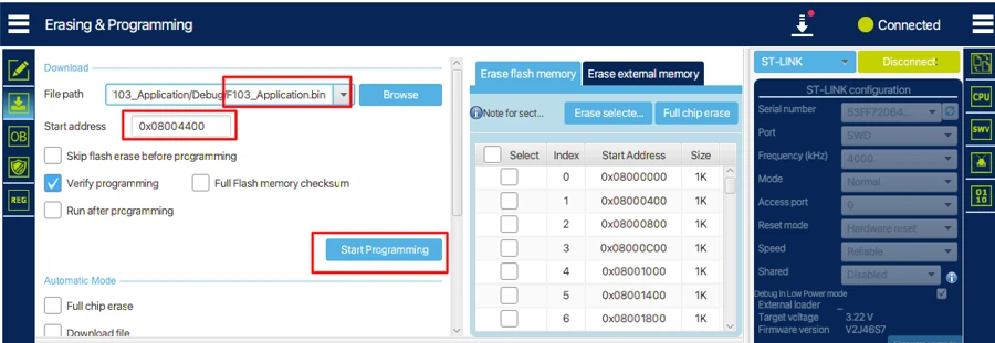
With both binaries flashed, the STM32 is ready to execute the bootloader first and then jump to the application.
Output and Verification
After flashing both the bootloader and application, we will verify the flow of execution by viewing the logs on the serial console. We have also connected 2 LEDs to verify if everything is working correctly.
The image below shows how the LEDs along with the USB-to-UART module are connected to the STM32.
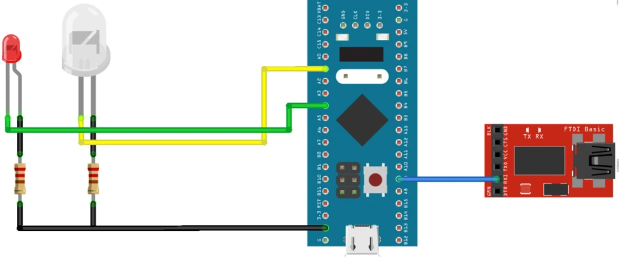
Once the board resets, the bootloader is executed first. If everything goes well, the application also starts executing next. This can be seen in the gif below.

You can see the control entered bootloader and the log gets printed on the serial console. Next, the control jumped t the app and we can see another log on the serial console.
The Green LED blinking every 500ms indicates that the application is running well.
You can view the detailed working and explanation in the video below.
Video Tutorial
STM32 Custom Bootloader Video Tutorial
Prefer video? Check out this tutorial where we walk through creating a fully functional STM32 bootloader step by step. Learn how to set up the bootloader project, define the flash layout, implement a safe jump to the application, and verify execution with LEDs and UART logs. Follow along to see the complete process in action and make your own custom bootloader for STM32 microcontrollers.
Watch the STM32 Bootloader TutorialConclusion
In this tutorial, we covered the complete setup of a custom STM32 bootloader and application. We started by creating the bootloader project in CubeMX, configured the minimal required peripherals, and defined the flash memory layout. We then implemented the jump logic to transfer control from the bootloader to the application safely. After creating the application project, we relocated its vector table, enabled interrupts, and generated both binary files. Finally, we flashed the bootloader and application using STM32CubeProgrammer and verified their execution using UART logs and LEDs.
By following this process, you now have a working bootloader and application running on your STM32 board. The memory regions are correctly separated, the bootloader executes first, and the application runs after the jump. This provides a solid foundation for implementing firmware updates, application validation, and OTA support in future tutorials.
In the next tutorial, we will focus on bootloader validation and entry logic. You will learn how the bootloader decides whether to jump to the application, how to verify the application before execution, and how to handle cases where the application is missing or corrupted. This will make your bootloader more robust and production-ready.
Browse More STM32 Tutorials

Riverdi STM32-U5 Embedded Display
FreeRTOS Tutorials #8 -> Software Timers

STM32 UART PART 7 – How to use 1-Wire Protocol

STM32 ADC Part 4 – Multiple Channels with DMA Circular Mode
STM32 UART PART 4 – Receive Data using DMA

STM32 Timers #9. One Pulse Mode

STM32 Ethernet PART 6.2 – Configure HTTP Webserver using CGI
STM32 Bootloader Project Download
STM32 Bootloader FAQs
Subscribe
Login
0 Comments
Newest