
Published: October 24, 2025
Last Updated: February 6, 2026
Last Updated: February 6, 2026
Interfacing I2C LCD1602 with Arduino: Display Text, Numbers, and Custom Characters
The LCD1602 display is one of the most popular modules used to show text and data in Arduino projects. But wiring all those pins can be messy! Thankfully, the I2C LCD1602 module with the PCF8574 interface makes it much simpler. You only need two wires, SDA and SCL, to control the entire display.
In this tutorial, you’ll learn how to interface an I2C LCD1602 display with Arduino, find its I2C address, and use it to display strings, numbers, float values, and even hexadecimal values. We’ll also show how to create custom characters, such as smiley faces or custom icons, to make your display more interactive.
By the end of this guide, you’ll be able to connect, code, and customize your 16×2 I2C LCD, perfect for your next Arduino project.
Prerequisites:
Along with some basic knowledge of Arduino, you should also take a look at the Arduino I2C Tutorial covered a while back. This will help you understand the concept with much more clarity.
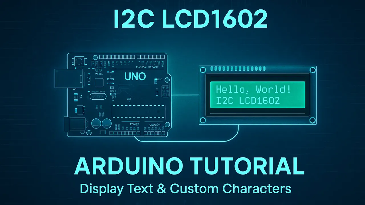
Table Of Contents
Introduction to I2C LCD1602 Display
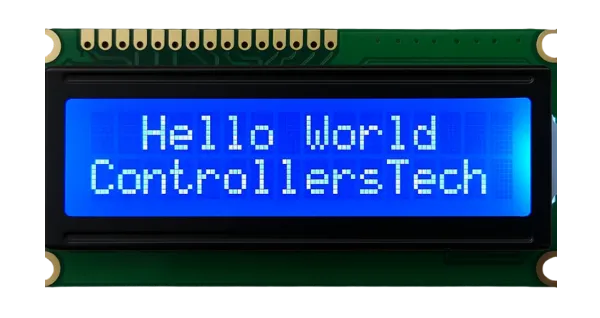
What is an LCD1602 Display?
The LCD1602 (also known as 16×2 LCD) is a simple and popular display module that can show 16 characters per line on 2 lines. Each character is displayed in a 5×8 pixel matrix, making it perfect for showing text, numbers, and basic symbols.
The display is based on the HD44780 controller, which is supported by many Arduino libraries. It usually operates at 5V, and you can easily adjust the screen contrast using a small potentiometer on the module.
Why Use the I2C Interface Instead of Parallel?
By default, the LCD1602 uses a parallel interface, which requires up to 8 data pins and 3 control pins, a total of 11 pins. This can quickly eat up your Arduino’s I/O pins.
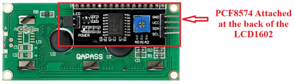
The I2C interface solves this problem by using just two pins, SDA (data) and SCL (clock), to control the entire display. The I2C adapter, usually based on the PCF8574 I/O expander chip, is soldered to the back of the LCD.
Using I2C makes your wiring much cleaner and allows you to connect multiple devices (like sensors or other displays) on the same two I2C lines. It’s a smart and space-saving choice for almost any Arduino project.
Components You’ll Need
To follow this tutorial, gather the following parts:
- Arduino Board (e.g., Arduino Uno, Nano, or Mega)
- I2C LCD1602 Display Module (with PCF8574 backpack)
- Jumper Wires (male-to-female or male-to-male, depending on setup)
- Breadboard (optional, for easy wiring)
- USB Cable (to connect Arduino to your computer)
Note: Before uploading your code, make sure you know your LCD’s I2C address, we’ll show how to find it in the next section.
Understanding the I2C Interface and PCF8574 Module
What is the PCF8574 I2C Expander?
The PCF8574 is an I/O expander chip that communicates with your Arduino using the I2C protocol. It acts as a bridge between your Arduino and the LCD1602 display. Instead of using many digital pins for data and control, this tiny chip lets you control the LCD using only two wires, SDA and SCL.
The PCF8574 chip has 8 output pins, which are internally connected to the LCD’s data and control lines. This means your Arduino sends I2C signals to the PCF8574, which then handles the actual parallel communication with the LCD module.
On the back of your LCD module, you’ll usually find a small I2C backpack containing the PCF8574 chip, a blue potentiometer (for contrast adjustment), and a jumper for backlight control.
Finding the I2C Address of Your LCD
Each I2C device has a unique 7-bit address that identifies it on the I2C bus. For most PCF8574-based LCD modules, this address is commonly 0x27 or 0x3F, but it can vary depending on the manufacturer.
To find your LCD’s I2C address, you can run a simple I2C scanner sketch on your Arduino:
#include <Wire.h>

void setup() {
  Wire.begin();
  Serial.begin(9600);
  Serial.println("Scanning for I2C devices...");
  for (byte i = 1; i < 127; i++) {
    Wire.beginTransmission(i);
    if (Wire.endTransmission() == 0) {
      Serial.print("I2C device found at address 0x");
      Serial.println(i, HEX);
    }
  }
}

void loop() {}Upload this code to your Arduino and open the Serial Monitor. You’ll see the detected I2C address printed there.
The image below shows the result of the I2C scanner code.
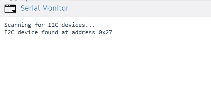
You can see the address 0x27 is detected by the scanner. We will use this address in our code when initializing the LCD.
Note: If no address is detected, check your wiring and ensure the SDA and SCL pins are correctly connected to your Arduino.
Changing the I2C Address Using A0, A1, and A2 Pins
The PCF8574 chip allows you to change its I2C address manually using the A0, A1, and A2 pins. These pins determine the lower three bits of the device’s address.
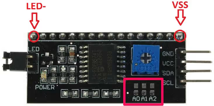
Each pin can be connected either to GND (logic 0) or VCC (logic 1) to form a unique combination. By default these pins are open, which means they are connected to VCC. The GND points are available beside each pin.
Here’s a quick reference table:
| A2 | A1 | A0 | I2C Address (PCF8574) | I2C Address (PCF8574A) |
|---|---|---|---|---|
| 0 | 0 | 0 | 0x20 | 0x38 |
| 0 | 0 | 1 | 0x21 | 0x39 |
| 0 | 1 | 0 | 0x22 | 0x3A |
| 0 | 1 | 1 | 0x23 | 0x3B |
| 1 | 0 | 0 | 0x24 | 0x3C |
| 1 | 0 | 1 | 0x25 | 0x3D |
| 1 | 1 | 0 | 0x26 | 0x3E |
| 1 | 1 | 1 | 0x27 | 0x3F |
By default, most I2C LCD modules have all three pins (A0, A1, A2) connected to VCC, giving an address of 0x27 or 0x3F.
If you need to use multiple I2C LCD modules on the same Arduino, you can change the address by cutting or bridging the solder pads for A0, A1, or A2 on the back of the module. Each unique combination gives a new address, allowing multiple displays to work together without conflicts.
Example: If your LCD currently uses address 0x27, and you connect A0 to GND, the new address will be 0x26. This way you can now control 2 different LCD just the 2 wires.
Common Variants of I2C LCD Modules
There are a few variants of the I2C LCD1602 modules available in the market, mainly depending on the type of PCF8574 chip and address configuration:
- PCF8574 (base chip) – Common address:
0x20 to 0x27 - PCF8574A (alternate version) – Common address:
0x38 to 0x3F - Different Backlight Control Versions – Some have a jumper for LED backlight; others use software control
- Different PCB Layouts – Potentiometer and pins may be placed differently, but functionally they’re identical
Make sure to note your module’s exact type and address before proceeding, it ensures your LCD initializes correctly in your Arduino sketch.
Circuit Diagram and Connections
Wiring I2C LCD1602 with Arduino UNO
Connecting an I2C LCD1602 display to an Arduino UNO is very simple because it only needs two communication wires, SDA and SCL, instead of the many pins required by a parallel LCD.
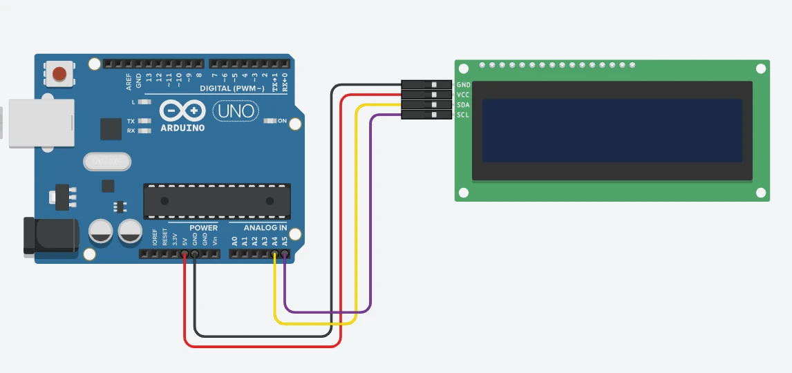
Here’s how to wire it:
| I2C LCD1602 Pin | Arduino UNO Pin | Description |
|---|---|---|
| VCC | 5V | Powers the LCD module (some versions also work with 3.3V) |
| GND | GND | Common ground connection |
| SDA | A4 | Serial Data line for I2C communication |
| SCL | A5 | Serial Clock line for I2C communication |
Note:
- On Arduino Mega, the SDA and SCL pins are 20 (SDA) and 21 (SCL).
- On Arduino Leonardo or Micro, use SDA = 2 and SCL = 3.
Once the connections are made, plug in your Arduino, and you’re ready to test the display using the I2C scanner code to confirm communication.
If the LCD doesn’t light up, check the backlight jumper and ensure the contrast potentiometer is adjusted correctly. Sometimes the characters are displayed but not visible due to low contrast.
Pin Description and Power Requirements
The I2C LCD1602 module typically has a 4-pin interface. Let’s take a quick look at what each pin does:
- VCC – Supplies power to the LCD (usually 5V, but some versions support 3.3V).
- GND – Common ground connection between Arduino and LCD.
- SDA (Serial Data) – Carries the data signals between Arduino and the PCF8574 chip.
- SCL (Serial Clock) – Provides the timing signal for synchronization of data transfer.
Most I2C LCD modules operate on 5V DC and consume around 20–30 mA when the backlight is ON. The contrast can be adjusted using the blue potentiometer located on the I2C backpack.
If you wish to turn off the backlight, you can either remove the jumper on the backlight pins or control it via software, depending on your module version.
Arduino Code to Display Text on LCD1602
After connecting your I2C LCD1602 display and finding its address, the next step is to program it using Arduino. With the LiquidCrystal_I2C library, you can easily display strings, numbers, and even scrolling messages on your LCD.
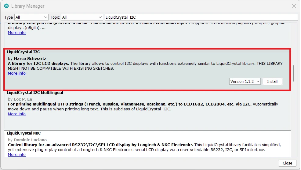
Installing the LiquidCrystal_I2C Library
Before writing the code, install the LiquidCrystal_I2C library:
- Open Arduino IDE.
- Go to Sketch → Include Library → Manage Libraries.
- Search for “LiquidCrystal_I2C”.
- Install the version by Frank de Brabander or Marco Schwartz.
This library simplifies LCD control using easy functions like .init(), .setCursor(), .print(), and .scrollDisplayLeft().
Note: The Wire library is included by default in Arduino IDE and handles the I2C communication.
Common Functions of LiquidCrystal_I2C Library
The table below covers all the basic functions you’ll need for printing text, numbers, scrolling, and creating custom characters on an I2C LCD1602.
| Function | Syntax | Description / Usage |
|---|---|---|
lcd.init() | lcd.init(); | Initializes the LCD. Must be called in setup() before printing text. |
lcd.backlight() | lcd.backlight(); | Turns on the LCD backlight. |
lcd.noBacklight() | lcd.noBacklight(); | Turns off the LCD backlight. |
lcd.clear() | lcd.clear(); | Clears the display and resets cursor to (0,0). |
lcd.setCursor() | lcd.setCursor(col, row); | Moves the cursor to a specific column and row. |
lcd.print() | lcd.print(value); | Prints text, numbers, float, or hex at the current cursor position. |
lcd.scrollDisplayLeft() | lcd.scrollDisplayLeft(); | Scrolls the entire display one character to the left. |
lcd.scrollDisplayRight() | lcd.scrollDisplayRight(); | Scrolls the entire display one character to the right. |
lcd.createChar() | lcd.createChar(location, byte[]); | Creates a custom character (0–7) in CGRAM. |
lcd.home() | lcd.home(); | Moves the cursor to (0,0) without clearing the display. |
lcd.blink() | lcd.blink(); | Makes the cursor blink at the current position. |
lcd.noBlink() | lcd.noBlink(); | Stops the blinking cursor. |
lcd.cursor() | lcd.cursor(); | Shows the cursor at the current position. |
lcd.noCursor() | lcd.noCursor(); | Hides the cursor. |
Basic Code Example to Print a String
Here’s a simple code to print text on your I2C LCD1602:
#include <Wire.h>
#include <LiquidCrystal_I2C.h>

// Replace 0x27 with your LCD's I2C address
LiquidCrystal_I2C lcd(0x27, 16, 2);

void setup() {
  lcd.init();          // Initialize the LCD
  lcd.backlight();     // Turn on the backlight
  lcd.setCursor(0, 0); // First row
  lcd.print("Hello, World!");
  lcd.setCursor(0, 1); // Second row
  lcd.print("I2C LCD1602");
}

void loop() {
  // Nothing here for now
}Here is how the code works:
#include <Wire.h>and#include <LiquidCrystal_I2C.h>→ Include libraries for I2C communication and LCD control.LiquidCrystal_I2C lcd(0x27,16,2);→ Creates an LCD object with I2C address0x27and size 16×2.lcd.init();→ Initializes the LCD.lcd.backlight();→ Turns on the backlight.lcd.setCursor(col,row);→ Moves the cursor to the specified column and row. We have 2 Rows (0 & 1) and 16 Columns (0 to 15).lcd.print("text");→ Displays text at the current cursor position.
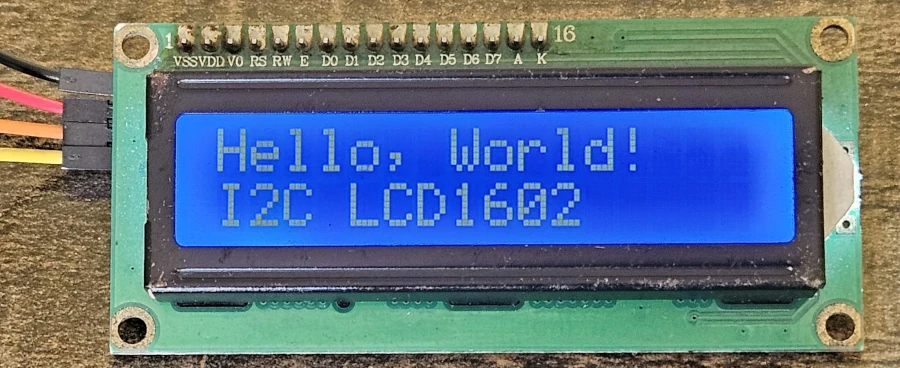
Basically, this code prints “Hello, World!” on the first line and “I2C LCD1602” on the second line. If you see a blank screen, try adjusting the contrast knob on the module.
The image below shows the output of this code. You can see the “Hello, World!” is printed on the 1st row, whereas, “I2C LCD1602” is printed on the 2nd row.
Displaying Numbers, Float Values, and Hex Values
You can print integers, floating-point numbers, and even hexadecimal values using the same .print() function.
#include <Wire.h>
#include <LiquidCrystal_I2C.h>

LiquidCrystal_I2C lcd(0x27, 16, 2);

void setup() {
  lcd.init();
  lcd.backlight();

  int number = 1234;
  float voltage = 5.123;

  lcd.setCursor(0, 0);  // First row
  lcd.print("Int: ");
  lcd.print(number);

  lcd.setCursor(0, 1);  // Second row
  lcd.print("Float: ");
  lcd.print(voltage, 2); // 2 decimal places

  delay(3000);
  lcd.clear();

  lcd.setCursor(0, 0);
  lcd.print("Hex: 0x");
  lcd.print(number, HEX); // Display number in hexadecimal
}

void loop() {}Note: You can control how many decimal places to show by changing the second argument in lcd.print() (e.g., lcd.print(value, 3)).
The gif below shows the output of this code. You can see the number, float and hex, everything is printing just fine.

Scrolling Text on I2C LCD1602
If your message is longer than 16 characters, you can make it scroll across the display. This is great for showing long strings or smooth text animations.
Here’s an example:
#include <Wire.h>
#include <LiquidCrystal_I2C.h>

LiquidCrystal_I2C lcd(0x27, 16, 2);

void setup() {
  lcd.init();
  lcd.backlight();

  lcd.setCursor(0, 0);
  lcd.print("Scrolling Message Demo");
  delay(1000);
}

void loop() {
  // Scroll text to the left
  for (int i = 0; i < 20; i++) {
    lcd.scrollDisplayLeft();
    delay(300);
  }

  delay(1000);

  // Scroll text back to the right
  for (int i = 0; i < 20; i++) {
    lcd.scrollDisplayRight();
    delay(300);
  }

  delay(1000);
}Explanation:
lcd.scrollDisplayLeft()moves the text one space to the left.lcd.scrollDisplayRight()moves it to the right.- Adjust the delay value to control scrolling speed.
The gif below shows the lcd1602 display scrolling in both directions.

Creating Custom Characters on I2C LCD1602
How LCD Custom Characters Work (CGRAM Explained)
The LCD1602 allows you to create up to 8 custom characters (numbered 0–7). These are stored in the CGRAM (Character Generator RAM).
- Each character is a 5×8 pixel matrix.
- You define a character by creating an array of 8 bytes, where each byte represents a row of pixels.
1→ Pixel ON0→ Pixel OFF
- Once defined, you can display your custom character using
lcd.write(location).
How it works in short:
- Define the pattern in an 8-byte array.
- Use
lcd.createChar()to store it in CGRAM. - Display it using
lcd.write().
Note: Custom characters are perfect for smileys, arrows, battery icons, or any small symbols you want to show on your LCD.
Example Code to Create Custom Icons or Symbols
Here’s an example showing how to create a smiley face on an I2C LCD1602:
#include <Wire.h>
#include <LiquidCrystal_I2C.h>
LiquidCrystal_I2C lcd(0x27, 16, 2);
// Define a custom character (smiley face)
byte smiley[8] = {
0b00000,
0b01010,
0b01010,
0b00000,
0b10001,
0b01110,
0b00000,
0b00000
};
void setup() {
lcd.init();
lcd.backlight();
// Create the custom character at location 0
lcd.createChar(0, smiley);
// Display the custom character
lcd.setCursor(0, 0);
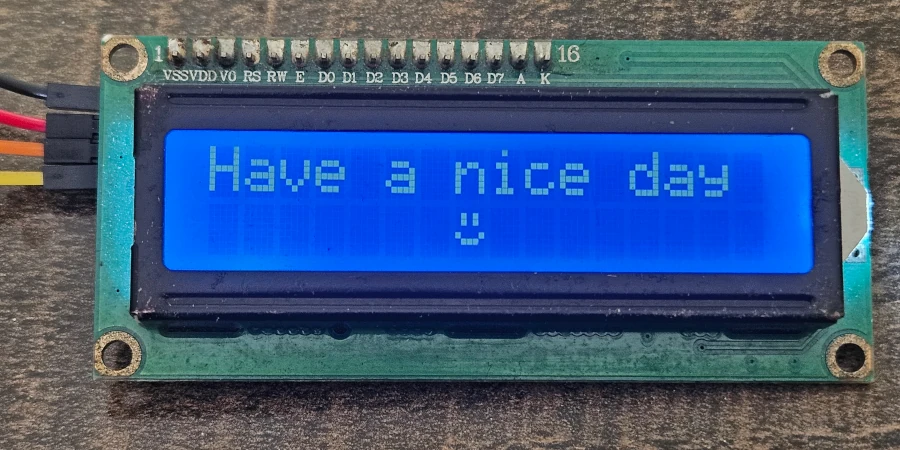
lcd.print("Have a nice day ");
lcd.setCursor(7, 1); // Go to 6th column in 2nd row
lcd.write(byte(0)); // Display the smiley at the end
}
void loop() {
// Nothing here
}Explanation:
byte smiley[8]→ Defines the 5×8 pixel pattern of the custom character.lcd.createChar(0, smiley);→ Stores the character in CGRAM slot 0.lcd.write(byte(0));→ Displays the custom character on the screen.
You can define up to 8 custom characters (locations 0–7) and reuse them in your project for small icons or symbols.
The image below shows the result on the LCD1602 Display. You can see the custom character (smiley) is printed on the 2nd Row.
Example code to print multiple custom characters
Here is an example to create and display multiple custom characters at the same time.
#include <Wire.h>
#include <LiquidCrystal_I2C.h>
// I2C address and 16x2 LCD
LiquidCrystal_I2C lcd(0x27, 16, 2);
// Define 5 custom characters (5x8 pixels each)
byte char1[8] = {0x00,0x0A,0x0A,0x00,0x11,0x0E,0x00,0x00}; // Smiley
byte char2[8] = {0x04,0x0E,0x15,0x04,0x04,0x04,0x04,0x00}; // Arrow up
byte char3[8] = {0x04,0x04,0x04,0x04,0x15,0x0E,0x04,0x00}; // Arrow down
byte char4[8] = {0x00,0x0A,0x0A,0x0A,0x11,0x0E,0x00,0x00}; // Another smiley
byte char5[8] = {0x00,0x04,0x0E,0x1F,0x0E,0x04,0x00,0x00}; // Heart
void setup() {
lcd.init();
lcd.backlight();
// Create custom characters at positions 0-4
lcd.createChar(0, char1);
lcd.createChar(1, char2);
lcd.createChar(2, char3);
lcd.createChar(3, char4);
lcd.createChar(4, char5);
lcd.setCursor(0, 0);
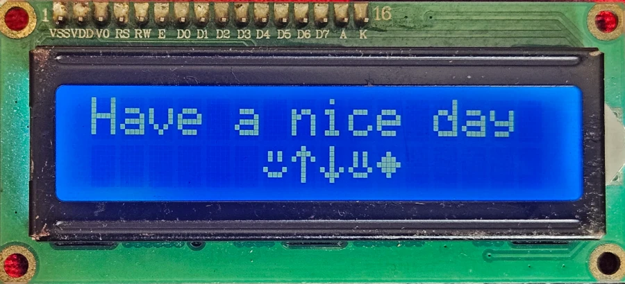
lcd.print("Have a nice day ");
// Display custom characters
lcd.setCursor(6,1);
lcd.write(byte(0));
lcd.write(byte(1));
lcd.write(byte(2));
lcd.write(byte(3));
lcd.write(byte(4));
}
void loop() {
// Nothing here; characters are static
}Explanation:
- Each
byte charX[8]defines a 5×8 pixel custom character. lcd.createChar(location, byteArray)stores the character in CGRAM location 0–7.lcd.write(byte(location))prints the custom character at the cursor.- In this example, 5 custom icons are displayed on the second row, while the first row shows the string.
The image below shows the output of this code. You can see the first row displays the string, while the custom characters are printed on the second row.
LCD1602 5×8 Custom Character Generator
You can generate the custom characters using the tool below. Click on the squares to toggle pixels ON (black) or OFF (white). After finishing your design, click “Generate Code” to get the Arduino byte array.
How to Use
Draw your character on the 5×8 grid below. Each row represents 5 pixels. Once done, click “Generate Code” to get the code, which you can directly use with lcd.createChar() in Arduino.
Generated Arduino Code (Hex):
Common Errors and Troubleshooting Tips
LCD Showing Blank Screen or Random Characters
If your LCD displays nothing or garbled/random characters, it’s usually caused by one of the following:
- Incorrect wiring – Make sure SDA, SCL, VCC, and GND are correctly connected.
- Power issues – Ensure your LCD module gets proper 5V (or 3.3V if supported).
- Contrast not set – Some modules need contrast adjustment using the onboard potentiometer.
- I2C address mismatch – If the address in your code does not match the module’s address, the LCD won’t display correctly.
Tip: Run an I2C scanner sketch to verify the module address.
Adjusting Contrast Using Potentiometer
Most I2C LCD modules have a small potentiometer (usually blue) on the back:
- Turn it slowly while the LCD is powered.
- Adjust until the text becomes clearly visible.
- If the text is very faint or not visible at all, the contrast needs adjustment.
Tip: Always adjust contrast after wiring and powering the LCD, never while the Arduino is off.
Incorrect I2C Address Issue
If the LCD does not respond or shows random characters:
- Check the I2C address set in your code, e.g.,
0x27. - Different modules may have addresses like
0x3F,0x27, or others. - Use the simple I2C scanner sketch to find your LCD’s address.
Once you identify the address, update your LiquidCrystal_I2C lcd(0xXX,16,2) line with the correct value.
Conclusion
In this tutorial, we covered everything you need to know to interface an I2C LCD1602 with Arduino. We started with understanding the I2C interface and the PCF8574 module, including how to find and change the LCD address. We then went through the circuit diagram and connections, followed by Arduino code examples to display strings, numbers, floats, hex values, and even scrolling text. Additionally, we explored creating custom characters using CGRAM and provided a practical HTML tool to generate the byte array for custom symbols. Finally, we discussed common errors and troubleshooting tips to help beginners get their LCDs working correctly.
The I2C LCD1602 is widely used in many projects due to its simplicity and low pin usage. You can use it in applications such as:
- Arduino sensor displays (temperature, humidity, distance, etc.)
- Clocks and timers
- Menu-driven interfaces for embedded systems
- DIY gadgets and robotics projects to show status messages
- Educational projects for learning microcontroller programming
This display module is versatile, easy to use, and perfect for adding a visual interface to your Arduino or microcontroller projects.
Browse More Arduino Display Tutorials
Interfacing ST7735 TFT Display with Arduino – Display Text, Graphics, and Images from SD Card
Interface SH1106 I2C 1.3” OLED Display with Arduino – Full Guide with Bitmaps and Animations
How to Interface MAX7219 7 Segment Display with Arduino | Display Text, Scrolling Message, and Time
Arduino ST7920 Tutorial (128×64 LCD): Wiring, Setup, U8g2, and Text Display Guide
Arduino ST7920 Display Graphics Guide: Shapes, Icons, Bitmaps, and UI Design
Arduino ST7920 Graphics Guide: How to Create Scrolling Text, Animations and Page Transitions (U8g2)
ST7920 Arduino Projects Tutorial: Real-Time Graphs, Menu System, and Full Dashboard UI using U8g2
Arduino I2C LCD1602 Project Download
Arduino I2C LCD1602 FAQs
Subscribe
Login
0 Comments
Newest
