Published: November 8, 2025
Last Updated: February 6, 2026
Last Updated: February 6, 2026
Interface MAX7219 7 Segment Display with Arduino
The MAX7219 7-segment display module is a simple and efficient way to show numbers, text, and symbols using an Arduino. It uses the MAX7219 driver IC, which allows you to control up to eight 7-segment displays with just three Arduino pins. This makes it ideal for projects like clocks, counters, and scrolling message boards.
In this tutorial, you’ll learn how to interface the MAX7219 7-segment display with Arduino step by step. We’ll cover the wiring, required libraries, and example codes to display static text, scrolling messages, and even real-time clock data.
Table Of Contents
- Introduction to MAX7219 7 Segment Display
- Components Required for This Project
- Circuit Diagram and Connections
- Arduino Code to Display Static Text
- Display Scrolling Text on MAX7219
- Displaying Numbers and Creating a Counter
- Common Issues and Troubleshooting
- Applications of MAX7219 7 Segment Display
- Conclusion
Introduction to MAX7219 7 Segment Display
The MAX7219 7-segment display module is a popular and easy-to-use display driver for Arduino projects. It helps you control multiple 7-segment displays, LEDs, or even dot matrix modules using very few pins. Whether you want to build a digital clock, a counter, or a scrolling display, the MAX7219 makes the job simple and efficient.
What is MAX7219 Module
The MAX7219 module is based on the MAX7219 integrated circuit from Maxim Integrated. It is designed to drive up to eight 7-segment displays using serial communication. This means instead of connecting each segment and digit to individual Arduino pins, you can control all of them using just three pins — DIN, CS, and CLK.
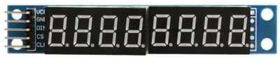
The module typically comes with a set of 8 digits arranged in a single line, making it perfect for displaying numbers or short messages. Each segment is driven internally by the MAX7219 chip, which handles brightness control, multiplexing, and current limiting automatically.
How the MAX7219 Controls 7 Segment Displays
The MAX7219 works by sending data serially from the Arduino to the chip. The chip then decodes this data and lights up the correct segments on the display. It uses SPI-like communication, where data is sent bit by bit through the DIN pin and synchronized by the CLK pin. The CS pin tells the chip when a complete set of data has been sent.
Inside the MAX7219, a multiplexing system quickly switches between digits so that all segments appear lit at the same time. This process happens so fast that it’s invisible to the human eye. You can also control the brightness of the entire display using a single command in your Arduino code.
Advantages of Using MAX7219 with Arduino
Using the MAX7219 with Arduino has many advantages. The biggest one is that it reduces the number of pins required to control multiple 7-segment displays. Without it, you’d need dozens of pins to drive 8 digits, but with the MAX7219, you only need three.
It also simplifies programming since the chip handles complex tasks like multiplexing and current control automatically. The MAX7219 can be daisy-chained to connect multiple modules together, allowing you to create longer displays for scrolling messages or larger projects.
Overall, it’s a compact, efficient, and beginner-friendly module that makes displaying numbers and text on Arduino easy and reliable.
Components Required for This Project
Before we begin connecting and coding, let’s gather all the parts and tools needed for this project. The good thing about the MAX7219 7-segment display is that it requires only a few basic components, making it ideal for beginners and quick prototypes.
List of Hardware Components
Here’s a complete list of hardware components you’ll need:
- Arduino Board – You can use any Arduino, such as Arduino Uno, Nano, or Mega.
- MAX7219 7-Segment Display Module – The main display driver module we’ll use.
- Jumper Wires (Male to Female) – For connecting the display to the Arduino.
- Breadboard (optional) – Makes wiring easier and cleaner.
- RTC Module (DS3231 or DS1307) – Optional, only needed if you want to display the current time.
- USB Cable – To upload the code and power the Arduino.
Make sure to double-check the orientation of the display before powering it up to avoid any damage.
Software Tools and Libraries Needed
To program the Arduino and make the MAX7219 work, we need a few software tools and libraries.
- Arduino IDE – The main software used to write and upload code to your Arduino. You can download it from the Arduino official website.
- LedControl Library – This library simplifies communication between Arduino and the MAX7219 display. It allows you to easily send characters, control brightness, and manage multiple displays.
- RTClib (optional) – Required if you’re using an RTC module to display time.
You can install these libraries directly from the Arduino Library Manager by searching their names, or download them from GitHub and add them manually.
Once everything is ready, we can move on to wiring the MAX7219 with Arduino and getting our first text displayed on the screen.
Circuit Diagram and Connections
Now that we have all the required components, it’s time to connect the MAX7219 7-segment display module to the Arduino. The wiring is quite simple because the MAX7219 communicates using only three pins — making it both beginner-friendly and efficient.
MAX7219 7 Segment Pinout
Before connecting the MAX7219 to your Arduino, it’s important to understand the pinout of the MAX7219 7-segment display module. The module comes with 5 input pins for communication and power, and several output pins that connect internally to the individual LED segments.
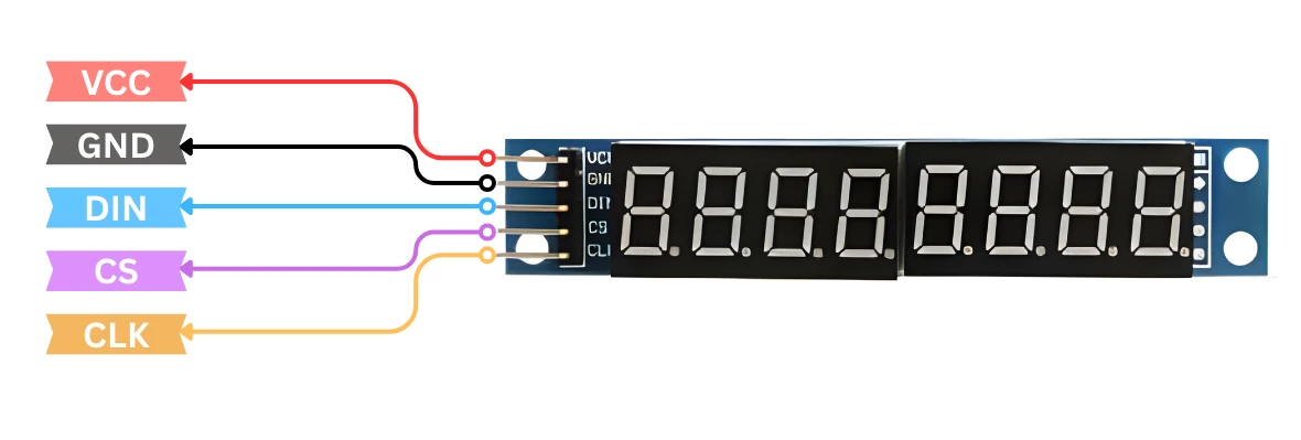
The MAX7219 uses SPI-like serial communication, which means you can control it using only three data pins from your Arduino — making it simple and efficient for multiple displays.
Here’s a clear breakdown of the pins and their functions:
| Pin Name | Pin Type | Function |
|---|---|---|
| VCC | Power | Provides power to the MAX7219 module. Connect to 5V on the Arduino. |
| GND | Ground | Common ground between the MAX7219 module and Arduino. |
| DIN | Data Input | Serial data input pin. Connect to the Arduino’s MOSI pin (usually D11 on Uno). |
| CS | Chip Select | Used to select the MAX7219 module for communication. Connect to any digital pin (e.g., D10). |
| CLK | Clock | Serial clock input. Connect to the Arduino’s SCK pin (usually D13 on Uno). |
In most ready-made MAX7219 7-segment modules, the internal wiring between the DIG and SEG pins is already handled, so you only need to connect the VCC, GND, DIN, CS, and CLK pins to the Arduino. This makes setup very simple and avoids the need for external resistors, as the MAX7219 already includes built-in current control for the LEDs.
Wiring MAX7219 with Arduino
The MAX7219 module has five main pins for connection: VCC, GND, DIN, CS, and CLK. The image below shows the connection between Arduino UNO and the module.
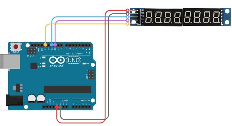
Here’s how you can connect them to your Arduino board:
| MAX7219 Pin | Arduino Pin | Description |
|---|---|---|
| VCC | 5V | Powers the display module |
| GND | GND | Common ground connection |
| DIN | D11 | Data input pin (SPI MOSI) |
| CS | D10 | Chip select pin |
| CLK | D13 | Clock signal pin (SPI SCK) |
Tip: You can use any other digital pins for DIN, CS, and CLK if needed. Just make sure to update them in the Arduino code.
If you’re using multiple MAX7219 modules for a scrolling display, you can daisy-chain them by connecting the DOUT pin of the first module to the DIN pin of the next one.
Understanding the Connection Pins:
Let’s briefly understand what each pin does:
- VCC: Supplies power to the MAX7219. It usually runs at 5V, which makes it compatible with most Arduino boards.
- GND: Common ground shared between the Arduino and the module.
- DIN (Data In): This pin receives serial data from the Arduino. The data contains which segments should be ON or OFF.
- CS (Chip Select): It tells the MAX7219 when to start or stop receiving data.
- CLK (Clock): It provides timing signals for data transfer between Arduino and the display.
These three communication pins (DIN, CS, and CLK) follow a serial protocol similar to SPI, which makes the connection very fast and efficient.
Arduino Code to Display Static Text
This section shows how to install the library and how to write simple Arduino code to show a static string on the MAX7219 7-segment module. The code is small and easy to adapt.
Installing the LedControl Library
- Open the Arduino IDE.
- Go to Sketch → Include Library → Manage Libraries.
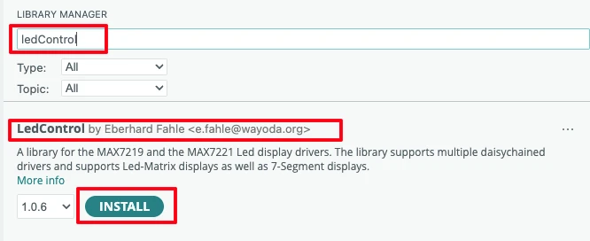
- In the Library Manager search box type LedControl.
- Find LedControl by Eberhard Fahle and click Install.
- Wait until installation finishes.
- Restart the Arduino IDE (optional but helps).
This library gives easy functions to control MAX7219 modules. It handles sending data and brightness control.
Adding the Font File (fonts.h)
Before we can display custom text on our 7-segment display, we need a font file that defines how each character should appear on the display.
Copy the fonts.h file from the project folder (downloadable in the end) in your Arduino project folder. This file will contain a lookup table (an array) that maps each printable ASCII character — letters, numbers, and symbols — to the corresponding 7-segment LED pattern.
Each byte in the array represents one character:
- Every bit corresponds to one segment (A–G and DP).
- A bit value of
1turns that segment ON, and0turns it OFF. - The MSB (bit 7) controls the decimal point (DP), while the lower 7 bits control segments A–G.
This approach allows us to design custom shapes for each character — for example, to show both uppercase and lowercase letters, special symbols, or even icons like “°C”.
Once the file is added, make sure to include it at the top of your Arduino code using:
#include "fonts.h"This makes the font table accessible from your main sketch.
Example Code to Display a String
The following code demonstrates how to display a static message on the MAX7219-based 7-segment display using the LedControl library and our custom font file.
#include <LedControl.h>
#include "fonts.h"

// Pin connections
const int DIN_PIN = 11;   // Data (MOSI)
const int CLK_PIN = 13;   // Clock (SCK)
const int CS_PIN  = 10;   // Chip Select (LOAD)

// Number of cascaded MAX7219 modules
const int NUM_MODULES = 1;

#define ENABLE_SEGMENT_REMAP   1   // Set to 1 if characters look mirrored
#define REVERSE_DIGIT_ORDER    0   // Set to 1 if digits appear reversed

LedControl lc = LedControl(DIN_PIN, CLK_PIN, CS_PIN, NUM_MODULES);

void setup() {
  lc.shutdown(0, false);   // Wake up MAX7219
  lc.setIntensity(0, 7);   // Set brightness (0–15)
  lc.clearDisplay(0);      // Clear all digits
}

void loop() {
  showStaticString("HELLO 12");
  while (true) delay(1000); // Keep displaying text
}

//---------------------------------------------------------------
// Helper function to fix segment bit order if needed
//---------------------------------------------------------------
uint8_t remap7seg(uint8_t v) {
  uint8_t dp = v & 0x80;        // Keep decimal point (bit 7)
  uint8_t low7 = v & 0x7F;      // Extract lower 7 bits (A–G)
  uint8_t rev = 0;
  for (uint8_t i = 0; i < 7; ++i)
    if (low7 & (1 << i)) rev |= (1 << (6 - i));
  return dp | rev;
}

//---------------------------------------------------------------
// Display a static string on the 7-segment display
//---------------------------------------------------------------
void showStaticString(const String &text) {
  String s = text;

  // Fit text to exactly 8 characters
  if (s.length() < 8) while (s.length() < 8) s += ' ';
  else if (s.length() > 8) s = s.substring(0, 8);

  for (int pos = 0; pos < 8; pos++) {
    char c = s.charAt(pos);

#if REVERSE_DIGIT_ORDER
    int displayPos = pos;
#else
    int displayPos = 7 - pos;
#endif

    byte pattern = FONT_7SEG[(int)c];

#if ENABLE_SEGMENT_REMAP
    pattern = remap7seg(pattern);
#endif

    lc.setRow(0, displayPos, pattern);
  }
}Code Explanation
Let’s go through what’s happening step-by-step:
- Library and Font File
We include theLedControl.hlibrary to communicate with the MAX7219 chip and the customfonts.hfile which defines how each character should look on the 7-segment display. - Hardware Setup
The pinsDIN,CLK, andCSare connected to the MAX7219’s data, clock, and load inputs.NUM_MODULESdefines how many MAX7219 ICs are daisy-chained (here, only one). - Initialization
Insidesetup(), we:- Wake up the MAX7219 chip using
shutdown(0, false) - Set brightness level with
setIntensity() - Clear any old data using
clearDisplay()
- Wake up the MAX7219 chip using
- Displaying the Message
TheshowStaticString()function takes a string (like"HELLO 12") and displays it across all 8 digits:- Pads or trims the string to fit exactly 8 characters.
- Looks up each character’s segment pattern from the font table (
FONT_7SEG). - Optionally reverses the bit order (if display wiring mirrors the segments).
- Sends the final 8-bit pattern to the MAX7219 using
lc.setRow().
- Optional Remapping
Depending on your hardware or how the display modules are mounted, the segments might appear mirrored or flipped.
By toggling theENABLE_SEGMENT_REMAPandREVERSE_DIGIT_ORDERdefines at the top, you can fix orientation issues without touching the code logic.
Output on the 7-Segment Display
After uploading the code to your Arduino, the MAX7219 will drive the 7-segment module to display the static text defined in the sketch.
If everything is wired correctly and the font file is added properly, you should see your custom message appear clearly across all digits — just like in the image below.
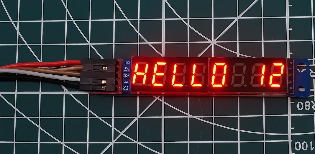
Your display may look mirrored or reversed depending on the module orientation. If that happens, simply toggle the ENABLE_SEGMENT_REMAP or REVERSE_DIGIT_ORDER defines at the top of the code.
Display Scrolling Text on MAX7219
One of the best features of the MAX7219 7-segment display is its ability to scroll text smoothly across the display. This effect makes your project look more dynamic and professional, especially when displaying messages longer than eight characters.
How Scrolling Text Works
The MAX7219 can display only eight characters per module. If your message is longer, you can scroll it horizontally by shifting the displayed characters one position at a time.
For example, if your message is “HELLO WORLD”, the display will first show “HELLO WO”, then “ELLO WOR”, and so on — giving the illusion of continuous movement.
The Arduino code does this by repeatedly updating the digits on the MAX7219 at a set time interval. The smaller the delay, the faster the text scrolls. You can also reverse the scroll direction by changing how characters are shifted.
Example Code for Scrolling String
Here’s a simple example to display a scrolling message on a single MAX7219 module:
#include <LedControl.h>
#include "fonts.h"

// Pin connections
const int DIN_PIN = 11;   // Data (MOSI)
const int CLK_PIN = 13;   // Clock (SCK)
const int CS_PIN  = 10;   // Chip Select (LOAD)
const int NUM_MODULES = 1; // One module = 8 digits

#define ENABLE_SEGMENT_REMAP   1   // Set to 1 if characters look mirrored
#define REVERSE_DIGIT_ORDER    0   // Set to 1 if digits appear reversed

LedControl lc = LedControl(DIN_PIN, CLK_PIN, CS_PIN, NUM_MODULES);

String message = " HELLO 12345678  ";   // Message to scroll
int scrollDelay = 300;               // Delay between shifts (ms)

//------------------------------------------------------------------
// Setup
//------------------------------------------------------------------
void setup() {
  lc.shutdown(0, false);   // Wake up display
  lc.setIntensity(0, 8);   // Brightness (0–15)
  lc.clearDisplay(0);      // Clear all digits
}

//------------------------------------------------------------------
// Main loop
//------------------------------------------------------------------
void loop() {
  scrollText(message);
}

//------------------------------------------------------------------
// Reverse the lower 7 bits if needed (fix mirrored characters)
//------------------------------------------------------------------
uint8_t remap7seg(uint8_t v) {
  uint8_t dp = v & 0x80;        // Keep decimal point (bit 7)
  uint8_t low7 = v & 0x7F;      // Extract lower 7 bits (A–G)
  uint8_t rev = 0;
  for (uint8_t i = 0; i < 7; ++i)
    if (low7 & (1 << i)) rev |= (1 << (6 - i));
  return dp | rev;
}

//------------------------------------------------------------------
// Scroll a message across the 7-segment display
//------------------------------------------------------------------
void scrollText(String text) {
  text += "        ";  // Add spaces at the end for smooth exit
  int len = text.length();

  for (int pos = 0; pos < len - 7; pos++) {
    for (int i = 0; i < 8; i++) {
      char c = text.charAt(pos + i);
      byte pattern = FONT_7SEG[(int)c];

#if ENABLE_SEGMENT_REMAP
      pattern = remap7seg(pattern);
#endif

#if REVERSE_DIGIT_ORDER
      int displayPos = i;
#else
      int displayPos = 7 - i;
#endif

      lc.setRow(0, displayPos, pattern);
    }
    delay(scrollDelay);
  }
}
Code Explanation:
- Font Lookup
Every character’s 7-segment pattern comes from theFONT_7SEGarray in yourfonts.hfile — not from the limited built-insetChar()support.
This means you can display any character, not just digits or a few letters. - Scrolling Logic
The functionscrollText()slides a window of 8 characters across the message.
After each step, the display updates and waits forscrollDelaymilliseconds before moving one position. - Bit Remapping (Optional)
Theremap7seg()helper reverses the order of segment bits (A–G) if your module shows mirrored characters.
Simply toggle the define:#define ENABLE_SEGMENT_REMAP 1→ Set to0if characters already display correctly. - Digit Order Reversal (Optional)
If the entire message scrolls backward, set:#define REVERSE_DIGIT_ORDER 1
Output — Scrolling Text on the 7-Segment Display
After uploading this sketch, your MAX7219 7-segment display will smoothly scroll the message across all digits, one character at a time. You should see each letter transition neatly from right to left, creating a continuous scrolling effect. This is shown in the gif below.

If the text appears mirrored or scrolls in the opposite direction, simply toggle the ENABLE_SEGMENT_REMAP or REVERSE_DIGIT_ORDER options at the top of the code to correct the display orientation.
Adjusting Scroll Speed and Direction
You can easily fine-tune how the text moves across your display. To change the scrolling speed, adjust the value of the scrollDelay variable — a smaller value makes the text move faster, while a larger value slows it down.
If the text scrolls in the wrong direction, toggle the REVERSE_DIGIT_ORDER define at the top of the code. Setting it to 1 reverses the digit order, causing the text to scroll in the opposite direction.
This gives you full control over how the message moves across the screen — making it ideal for ticker-style displays, information boards, or digital name badges.
Displaying Numbers and Creating a Counter
Apart from text, the MAX7219 is great for showing numbers such as sensor readings, timers, or counters. In this example, we’ll display an incrementing counter that updates every few hundred milliseconds, making it easy to visualize real-time updates.
Example Code — Counter Display
#include <LedControl.h>
#include "fonts.h"

// Pin connections
const int DIN_PIN = 11;   // Data (MOSI)
const int CLK_PIN = 13;   // Clock (SCK)
const int CS_PIN  = 10;   // Chip Select (LOAD)

// Number of cascaded MAX7219 modules
const int NUM_MODULES = 1;

#define ENABLE_SEGMENT_REMAP   1   // Set to 1 if characters look mirrored
#define REVERSE_DIGIT_ORDER    0   // Set to 1 if digits appear reversed

LedControl lc = LedControl(DIN_PIN, CLK_PIN, CS_PIN, NUM_MODULES);

// Counter speed control
const int counterDelay = 200;  // Delay between updates (ms)

void setup() {
  lc.shutdown(0, false);   // Wake up MAX7219
  lc.setIntensity(0, 7);   // Set brightness (0–15)
  lc.clearDisplay(0);      // Clear all digits
}

void loop() {
  displayCounter();
}

//---------------------------------------------------------------
// Helper function to fix segment bit order if needed
//---------------------------------------------------------------
uint8_t remap7seg(uint8_t v) {
  uint8_t dp = v & 0x80;        // Keep decimal point (bit 7)
  uint8_t low7 = v & 0x7F;      // Extract lower 7 bits (A–G)
  uint8_t rev = 0;
  for (uint8_t i = 0; i < 7; ++i)
    if (low7 & (1 << i)) rev |= (1 << (6 - i));
  return dp | rev;
}

//---------------------------------------------------------------
// Function to increment and display numbers continuously
//---------------------------------------------------------------
void displayCounter() {
  for (long num = 0; num <= 99999999; num++) {
    showNumber(num);
    delay(counterDelay);
  }
}

//---------------------------------------------------------------
// Function to display an 8-digit number
//---------------------------------------------------------------
void showNumber(long value) {
  char buffer[9];
  sprintf(buffer, "%8ld", value);  // Format to 8 characters (right-aligned)

  for (int pos = 0; pos < 8; pos++) {
    char c = buffer[pos];

#if REVERSE_DIGIT_ORDER
    int displayPos = pos;
#else
    int displayPos = 7 - pos;
#endif

    byte pattern = FONT_7SEG[(int)c];

#if ENABLE_SEGMENT_REMAP
    pattern = remap7seg(pattern);
#endif

    lc.setRow(0, displayPos, pattern);
  }
}
Code Explanation – Counter Display
- Font and Remap Setup:
The code includesfonts.h, which holds custom 7-segment patterns for all characters.
Theremap7seg()function flips the bit order when digits appear mirrored on certain displays. - Initialization:
Insetup(), the MAX7219 is powered on, brightness is set, and the display is cleared. - Main Loop:
ThedisplayCounter()function runs continuously, counting from0to99,999,999.
Each number is passed toshowNumber()and displayed with a short delay between updates. - Displaying the Number:
showNumber()formats the number into an 8-character string and shows each digit using the corresponding pattern fromFONT_7SEG[].
Optional definesENABLE_SEGMENT_REMAPandREVERSE_DIGIT_ORDERhelp correct the display orientation.
Output — Incrementing Counter
Once you upload the code, the display will count upward from 0 to 99,999,999, updating every 200 ms. Each digit changes smoothly, showcasing how numeric values can be displayed dynamically using the same font file.

If your digits appear reversed or mirrored, toggle the following defines at the top:
#define ENABLE_SEGMENT_REMAP 1
#define REVERSE_DIGIT_ORDER 0until the orientation looks correct.
Common Issues and Troubleshooting
While working with the MAX7219 7-segment display, you may encounter a few common issues, such as the display not lighting up, random flickering, or characters appearing mirrored or reversed. Most of these are easy to fix once you know what to look for.
Display Not Lighting Up
If the display remains blank after uploading the code, the issue is usually related to power or wiring.
Quick checklist:
- Ensure VCC is connected to the 5V pin on the Arduino (not 3.3V).
- Confirm GND from the module is connected to the Arduino’s GND.
- Check that DIN, CS, and CLK pins match the pin numbers defined in your code.
- Try running the
LCDemo7Segmentexample from the LedControl library to verify the module is functional. - If still off, increase brightness slightly using:
lc.setIntensity(0, 10);
Random or Flickering Segments
If you see flickering or random segments lighting up, it’s often caused by loose connections or electrical noise on the data lines.
How to fix it:
- Reseat all jumper wires and ensure solid contact — especially CLK, DIN, and CS.
- Keep GND connections common across all modules and the Arduino.
- Make sure your power supply provides enough current (each module may draw up to 300 mA).
- Add a 100 µF capacitor between VCC and GND near the display to smooth voltage fluctuations.
Reversed Digits (Displayed in Wrong Order)
If your digits appear reversed (e.g., the first character on the right instead of the left), this is related to display order.
Solution:
Toggle the REVERSE_DIGIT_ORDER define in your code:
#define REVERSE_DIGIT_ORDER 1Setting it to 1 reverses the display order, fixing the direction of text and numbers.
Mirrored or Inverted Characters
If letters or numbers appear mirrored (like a flipped “E” or “F”), the issue lies in the segment wiring order of your display.
Solution:
Enable segment remapping by setting:
#define ENABLE_SEGMENT_REMAP 1This calls the remap7seg() function in your code, which rearranges the segment bits to display characters correctly.
Incorrect or Jumbled Characters
If characters look garbled or wrong:
- Double-check your pin connections (DIN, CLK, CS) and ensure they match your code.
- Verify that your LedControl library is installed and working correctly.
- If you’re using a custom
fonts.h, confirm that each pattern (bit value) is correct — even a single wrong bit can distort a letter. - Re-upload your sketch after making corrections and reset the Arduino.
Applications of MAX7219 7 Segment Display
The MAX7219 7-segment display module is widely used in many Arduino and electronic projects because of its versatility and ease of use. It allows you to display numbers, letters, and animations using only a few pins, making it suitable for both small and large-scale applications.
Here are some of the most common and practical uses of the MAX7219 display module.
Digital Clock Projects
One of the most popular uses of the MAX7219 is in digital clock projects. When paired with an RTC module such as DS3231 or DS1307, it can display real-time hours, minutes, and even seconds.
You can create a compact and bright digital clock that runs independently and updates automatically. Many makers also add features like alarms, date display, and temperature readings. The clear and crisp segments of the MAX7219 make it easy to read from a distance, which is perfect for desktop or wall-mounted clocks.
Scoreboards and Counters
The MAX7219 is also great for electronic counters or scoreboards. It can quickly update numeric values such as game scores, event counters, or sensor readings.
For example, you can use it in a table tennis scoreboard, a visitor counter, or even a production line counter that tracks the number of items passing through a sensor.
Since the MAX7219 handles multiplexing internally, it ensures smooth updates with no visible flicker, even when numbers change rapidly.
Scrolling Message Boards
Another fun and creative application is building a scrolling message board. By chaining multiple MAX7219 modules together, you can display longer messages that move continuously across the screen.
This setup is commonly used for information displays, name tags, or announcement boards. You can program it to show any text, including sensor data, weather updates, or custom greetings.
With the help of Arduino, you can also make the message dynamic — for example, scrolling faster, changing direction, or updating text automatically based on serial input or network data.
The MAX7219 7-segment display is simple yet powerful. Whether it’s a digital clock, a real-time counter, or a scrolling display, this module makes it easy to add bright, clear, and professional-looking visual output to any Arduino project.
Conclusion
In this tutorial, you learned how to interface the MAX7219 7-segment display with Arduino and use it to show different types of data. Starting from understanding how the MAX7219 module works, you moved on to wiring it correctly, installing the necessary libraries, and writing Arduino code to display both static and scrolling text.
You also learned how to connect an RTC module like DS3231 or DS1307 to display real-time clock data on the MAX7219 display. Along the way, we discussed how to adjust brightness, control scroll speed, and fix common issues such as flickering or incorrect characters.
With these skills, you can now confidently use the MAX7219 in various Arduino projects — from digital clocks and scoreboards to scrolling message boards and other creative display applications. This small yet powerful module makes it easy to add a professional-looking numeric or text display to any project.
Browse More Arduino Display Tutorials

Arduino SSD1306 OLED 0.96″ Display Guide – Show Text, Numbers & Custom Animations
Interfacing ST7735 TFT Display with Arduino – Display Text, Graphics, and Images from SD Card
Interface SH1106 I2C 1.3” OLED Display with Arduino – Full Guide with Bitmaps and Animations
Arduino ST7920 Tutorial (128×64 LCD): Wiring, Setup, U8g2, and Text Display Guide
Arduino ST7920 Display Graphics Guide: Shapes, Icons, Bitmaps, and UI Design
Arduino ST7920 Graphics Guide: How to Create Scrolling Text, Animations and Page Transitions (U8g2)
ST7920 Arduino Projects Tutorial: Real-Time Graphs, Menu System, and Full Dashboard UI using U8g2
Arduino MAX7219 7-Segment Project Download
Arduino MAX7219 7-Segment FAQs
Subscribe
Login
0 Comments
Newest
