Home ▸ ESP32 Tutorials ▸ ESP32 UART ▸
Published: February 20, 2026
Last Updated: April 1, 2026
Last Updated: April 1, 2026
How to Use UART in Interrupt Mode on ESP32 (ESP-IDF)
In the previous parts of this series, we covered how to use UART in ESP32 using blocking mode and how to send and receive commands via UART. Blocking mode works fine for small data, but it holds up the CPU until the transfer finishes. That means other tasks can’t run on time.
This is where UART interrupt mode comes in. Instead of waiting, the CPU gets notified through events when data arrives. This keeps the system responsive and makes it possible to handle large amounts of data reliably.
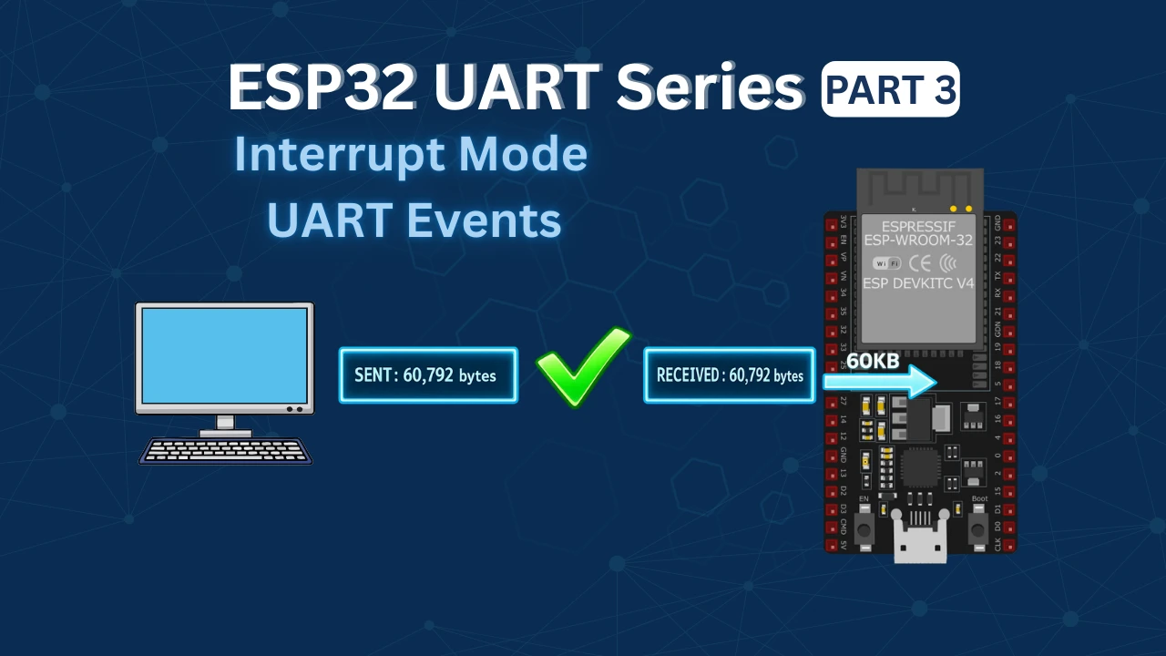
In this tutorial, we’ll use UART events in ESP-IDF to receive data on the ESP32. We’ll test it by sending tens of thousands of bytes from the computer and verifying that nothing is lost.
What is UART Interrupt Mode and Why Use It?
If you’ve already read the previous parts of this series, you know how blocking mode works. Interrupt mode is a step up from that, and once you understand the difference, you’ll know exactly when to use which approach.
How Blocking Mode Works
In blocking mode, when we call a UART receive function, the CPU stops and waits. It doesn’t do anything else until the data arrives or the timeout expires.
Here’s a simple example of what that looks like:
uart_read_bytes(UART_NUM, data, length, pdMS_TO_TICKS(1000));The CPU is stuck here until it either gets the data or the 1000ms timeout hits. During this time, no other task can use that CPU time effectively. For small data, this is fine. But when you’re receiving thousands of bytes, this becomes a real problem.
How Interrupt Mode Works
In interrupt mode, the CPU doesn’t wait around. Instead, the UART hardware watches for incoming data on its own. When data arrives, it fires an interrupt. The ESP-IDF driver catches this interrupt and posts an event to a queue.
We create a task that sits and waits on that queue. The moment an event arrives, the task wakes up, processes the data, and goes back to waiting. Between events, the CPU is free to do other things.
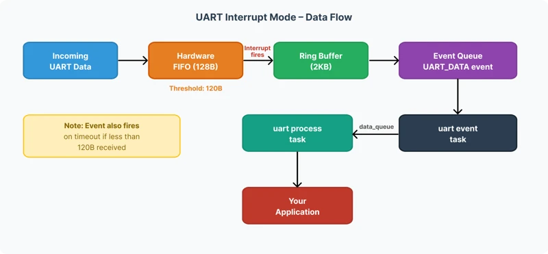
The diagram below shows the flow from data arriving at the UART pin to our task processing it.
The Role of the FIFO and Ring Buffer
The ESP32 UART hardware has a built-in FIFO buffer of 128 bytes. Think of it as a small staging area where incoming bytes sit before the driver picks them up.
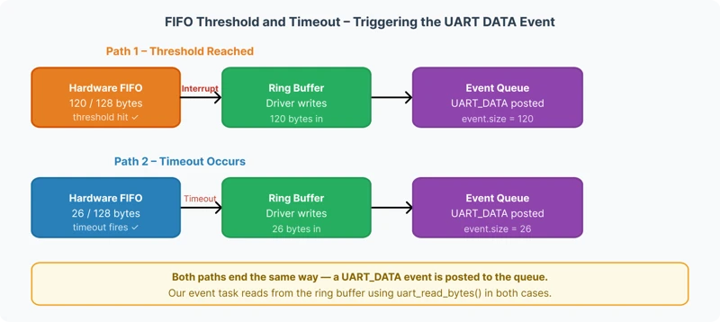
By default, the FIFO threshold is set to 120 bytes. So when 120 bytes fill up, the hardware fires an interrupt. The ESP-IDF driver responds to this interrupt and moves the data from the FIFO into the ring buffer — which is a larger software buffer that we define in our code.
We set our ring buffer to 2KB. This gives us enough room to hold data between events without losing anything.
There’s a second scenario too. If fewer than 120 bytes arrive and no more data comes in for a while, a timeout occurs. The driver treats this as a signal that the sender is done, and it generates a UART_DATA event anyway. This ensures no leftover bytes get stuck in the FIFO.
So a UART_DATA event fires in two situations:
- When 120 bytes fill the FIFO (threshold reached)
- When a timeout occurs with fewer bytes still in the FIFO
Why This Is Better Than Blocking Mode
The biggest advantage is that the CPU is free between events. Other FreeRTOS tasks can run normally while the UART waits for data. There’s no artificial delay blocking the rest of the system.
Here’s a quick comparison:
| Blocking Mode | Interrupt Mode | |
|---|---|---|
| CPU while waiting | Blocked | Free |
| Good for small data | Yes | Yes |
| Good for large data | No | Yes |
| Other tasks affected | Yes | No |
| Complexity | Simple | Moderate |
For most real-world applications interrupt mode is the right choice. Blocking mode is fine when you just need to grab a few bytes quickly and the simplicity is worth more than the overhead.
ESP32 UART Wiring Diagram
The ESP32 have 3 UARTs, UART0, 1 and 2. I am going to use the UART2 as the pins for UART2 are defined clearly on the board. This is shown in the picture below
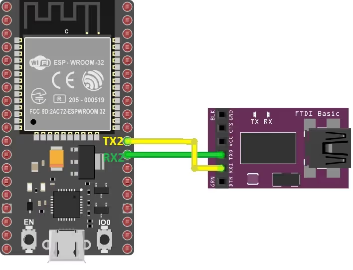
As shown in the image above, the RX2 and TX2 pins ( GPIO16 and GPIO17 respectively) represents the UART2 pins. The pins must be cross connected, Rx to TX and TX to RX.
| ESP32 Pin | FTDI Connection | Description |
|---|---|---|
| TX2 (GPIO 17) | RX | ESP32 transmits data to FTDI |
| RX2 (GPIO 16) | TX | ESP32 receives data from FTDI |
ESP32 UART Pin Mapping Explained
ESP32 UART interfaces are flexible and allow you to remap TX, RX, RTS, and CTS to almost any GPIO pin. Common pin configurations:
- UART0: TX (GPIO1), RX (GPIO3)
- UART1: TX (GPIO10), RX (GPIO9)
- UART2: TX (GPIO17), RX (GPIO16)
You can override default pins using uart_set_pin(). This is particularly useful if your board uses certain pins for other purposes.
Configuring UART in ESP-IDF for Interrupt Mode
Setting up UART for interrupt mode is straightforward. We configure the UART parameters, install the driver, assign the GPIO pins, and create the queues. Let’s go through each part.
UART Driver Installation and Parameters
Defining the Basics
First, we define the UART instance and the pins we’ll use. We’re sticking with UART2 and the same GPIO pins from the previous tutorials to keep things consistent.
#define UART_NUM    UART_NUM_2
#define TXD_PIN     17
#define RXD_PIN     16
#define BUF_SIZE (1024)We also define a buffer size of 1KB. We’ll use this as a base size when configuring the TX and RX buffers in the driver.
Configuring UART Parameters
Next, we fill in the uart_config_t structure. This defines how the UART peripheral behaves — baud rate, data bits, parity, and stop bits.
uart_config_t uart_config = {
.baud_rate = 115200,
.data_bits = UART_DATA_8_BITS,
.parity = UART_PARITY_DISABLE,
.stop_bits = UART_STOP_BITS_1,
.flow_ctrl = UART_HW_FLOWCTRL_DISABLE,
.source_clk = UART_SCLK_DEFAULT,
};This is the standard 8N1 configuration — 8 data bits, no parity, 1 stop bit. Hardware flow control is disabled since we’re not using RTS/CTS pins here.
Installing the UART Driver
This is the most important step. We call uart_driver_install to install the ESP-IDF UART driver. This function does several things at once — it allocates the RX and TX ring buffers and automatically creates the event queue.
uart_driver_install(UART_NUM, BUF_SIZE * 2, BUF_SIZE, 20, &event_queue, 0);Let’s break down each argument:
- uart_num –
UART_NUM_2selects UART2 as the peripheral we’re using. - rx_buffer_size –
BUF_SIZE * 2sets the RX ring buffer to 2KB. - tx_buffer_size –
BUF_SIZEsets the TX buffer to 1KB. - queue_size –
20means the event queue can hold up to 20 events at a time. - uart_queue –
&event_queueis the pointer where the created queue handle gets stored. - intr_alloc_flags –
0uses the default interrupt allocation flags.
One important note about the TX buffer — if you set it to 0, the UART transmission falls back to blocking mode. So always give it a proper size if you want fully non-blocking operation.
After installing the driver, we apply the UART parameters and assign the GPIO pins.
uart_param_config(UART_NUM, &uart_config);
uart_set_pin(UART_NUM, TXD_PIN, RXD_PIN, UART_PIN_NO_CHANGE, UART_PIN_NO_CHANGE);We pass UART_PIN_NO_CHANGE for the RTS and CTS pins since we’re not using hardware flow control.
Creating the Tasks
Once the driver is ready, we create two FreeRTOS tasks — one to handle UART events and another to process the received data. We’ll cover what these tasks do in detail in the next sections.
xTaskCreate(uart_event_task, "uart_event_task", 3072, NULL, 12, NULL);
xTaskCreate(uart_process_task, "uart_process_task", 2048, NULL, 11, NULL);Notice that the event task has a higher priority (12) than the process task (11). This is intentional. We want the event task to respond to incoming data as fast as possible. The process task can afford to wait a little longer.
Understanding the Event Queue and Ring Buffer
This part is key to understanding how interrupt mode actually works inside ESP-IDF. There are two layers of buffering happening here, and it’s worth knowing what each one does.
The Hardware FIFO
The ESP32 UART hardware has a built-in FIFO of 128 bytes. Every byte that comes in through the RX pin lands here first. The FIFO is a hardware buffer — the CPU isn’t involved yet at this point.
The driver sets a threshold of 120 bytes by default. When the FIFO reaches 120 bytes, it fires an interrupt. The driver catches this interrupt, moves the data from the FIFO into the ring buffer, and posts a UART_DATA event to the event queue.
The diagram below shows how data moves from the FIFO into the ring buffer when the threshold is reached or a timeout occurs.
The Ring Buffer
The ring buffer is a software buffer managed by the ESP-IDF UART driver. The driver moves the data from UART FIFO to this ring buffer. Our application then reads from this ring buffer using uart_read_bytes.
We set the ring buffer size to 2KB in uart_driver_install:
uart_driver_install(UART_NUM, BUF_SIZE * 2, ...); // RX ring buffer = 2KBThe ring buffer needs to be bigger than the FIFO. If it’s too small and we can’t read data fast enough, the UART_BUFFER_FULL event fires and we start losing data. Size it according to how much data your application receives at once.
The Event Queue
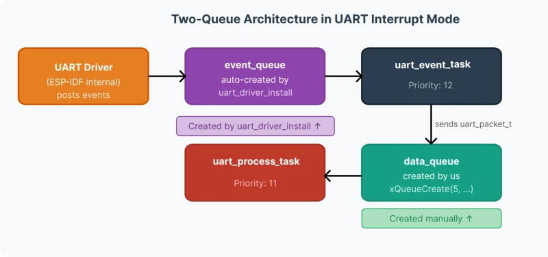
The event queue is what connects the UART driver to our application code. Every time the driver processes an interrupt — whether from the FIFO threshold or a timeout — it posts an event to this queue.
We don’t create this queue ourselves. It’s created automatically inside uart_driver_install and the handle is returned to us through the &event_queue pointer.
static QueueHandle_t event_queue;
// ...
uart_driver_install(UART_NUM, BUF_SIZE * 2, BUF_SIZE, 20, &event_queue, 0);The 20 in the arguments means the queue can hold up to 20 events at a time. If our task is slow and events pile up beyond 20, newer events get dropped. For most applications, 20 is more than enough.
The Data Queue
We also define a second queue ourselves — the data_queue. This one is different from the event queue. Its job is to pass the actual received data from the event task to the processing task.
typedef struct {
int len;
uint8_t *data;
} uart_packet_t;
static QueueHandle_t data_queue;We create it in app_main after the driver is installed:
data_queue = xQueueCreate(5, sizeof(uart_packet_t));This queue holds up to 5 uart_packet_t structures. Each structure carries a pointer to the dynamically allocated data and its length. We’ll see exactly how this is used in the next section when we write the event task.
The diagram below shows the relationship between the event queue and the data queue, and which task owns each one.
Handling UART Events in ESP-IDF
The uart_event_task is where all the action happens. This task runs in an infinite loop and blocks on the event queue using xQueueReceive. It does nothing until the UART driver posts an event. When an event arrives, the task wakes up, checks the event type, and handles it accordingly.
static void uart_event_task(void *pvParameters)
{
uart_event_t event;
for (;;) {
if (xQueueReceive(event_queue, (void *)&event, (TickType_t)portMAX_DELAY)) {
switch (event.type) {
// handle events here
}
}
}
}The switch statement checks the event type and routes it to the correct handler. Let’s look at the important ones.
The UART Data Event
The UART_DATA event is the one we care about most. It fires when new data is available in the ring buffer — either because the FIFO threshold was reached or a timeout occurred.
When this event fires, we need to do three things — allocate memory for the incoming data, read it from the ring buffer, and send it to the processing task.
Step 1 — Allocate Memory
We define a uart_packet_t instance and dynamically allocate memory for the incoming data using malloc.
case UART_DATA:
uart_packet_t pkt;
pkt.data = malloc(event.size);
if (pkt.data == NULL) {
ESP_LOGE("UART", "Malloc failed");
break;
}event.size tells us exactly how many bytes are waiting in the ring buffer, so we allocate precisely that much.
You might wonder why we use malloc instead of a global buffer. The reason is simple — if we used a global buffer, new incoming data could overwrite it before the processing task finishes reading it. With malloc, every packet gets its own dedicated memory. This makes the system safe and reliable.
Step 2 — Read the Data
We call uart_read_bytes to pull the data out of the ring buffer and into our allocated buffer. The function returns the actual number of bytes read, which we store in pkt.len.
ESP_LOGI("UART", "Data Event: Bytes=%d", event.size);
pkt.len = uart_read_bytes(UART_NUM, pkt.data, event.size, portMAX_DELAY);Step 3 — Send to the Data Queue
Now the packet is ready. We send it to data_queue so the processing task can pick it up.
xQueueSend(data_queue, &pkt, portMAX_DELAY);
break;The event task’s job is done here. It doesn’t process the data itself — it just reads it and passes it on. This keeps the event task fast and responsive.
Here is the complete UART_DATA case put together:
case UART_DATA:
uart_packet_t pkt;
pkt.data = malloc(event.size);
if (pkt.data == NULL) {
ESP_LOGE("UART", "Malloc failed");
break;
}
ESP_LOGI("UART", "Data Event: Bytes=%d", event.size);
pkt.len = uart_read_bytes(UART_NUM, pkt.data, event.size, portMAX_DELAY);
xQueueSend(data_queue, &pkt, portMAX_DELAY);
break;FIFO Overflow and Buffer Full Events
These two events are error conditions. They tell us that data is arriving faster than we’re processing it.
UART_FIFO_OVF — Hardware FIFO Overflow
This event fires when the hardware FIFO fills up completely before the driver can move the data to the ring buffer. When this happens, incoming bytes start getting dropped at the hardware level.
case UART_FIFO_OVF:
ESP_LOGE("uart", "hw fifo overflow");
uart_flush_input(UART_NUM);
xQueueReset(event_queue);
break;We flush the RX buffer and reset the event queue to recover from the error and get the system back to a clean state.
UART_BUFFER_FULL — Ring Buffer Full
This event fires when the ring buffer runs out of space. The driver has moved data from the FIFO, but the application isn’t reading it fast enough. The response is the same — flush and reset.
case UART_BUFFER_FULL:
ESP_LOGI("uart", "ring buffer full");
uart_flush_input(UART_NUM);
xQueueReset(event_queue);
break;The diagram below shows when each overflow event fires and at which stage the data gets dropped.
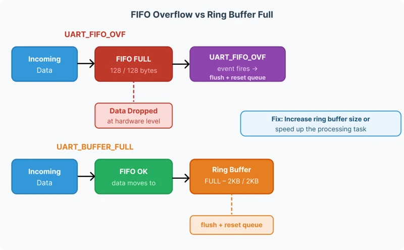
If you see these events during testing, it means either the ring buffer is too small or the processing task is too slow. Increasing BUF_SIZE or reducing the workload in the process task will fix it.
Processing Received Data with a Dedicated Task
Once the event task reads the data from the ring buffer, it needs to go somewhere for processing. We handle this in a separate dedicated task. Let’s look at why we do this and how it works.
Why Use a Separate Processing Task?
The event task has one job — respond to UART events as fast as possible. If we do any heavy processing inside it, it stays busy and can’t respond to the next event in time. The event queue fills up and we start losing data.
So we keep the event task light. It reads the data, packages it, and sends it to the data_queue. A separate processing task picks it up from there and does the actual work.
This separation also makes the code cleaner. The event task handles UART-level concerns. The process task handles application-level concerns. Each task does one thing well.
The uart_process_task
This task blocks on data_queue using xQueueReceive. It does nothing until a packet arrives. When one does, it processes the data and then frees the allocated memory.
Receiving the Packet
We define a uart_packet_t instance at the top of the task. Inside the loop, we wait on the queue indefinitely using portMAX_DELAY.
static void uart_process_task(void *pvParameters)
{
uart_packet_t pkt;
for (;;)
{
if (xQueueReceive(data_queue, &pkt, portMAX_DELAY))
{When a packet arrives, pkt contains the pointer to the data and its length — exactly what the event task packed into it.
Processing the Data
In this tutorial, we echo the data back through UART. So whatever the computer sends, the ESP32 sends it right back.
ESP_LOGI("uart", "processing data");
uart_write_bytes(UART_NUM, pkt.data, pkt.len);In your own project, replace uart_write_bytes with whatever your application needs — parse a command, store to flash, update a display, anything.
Freeing the Memory
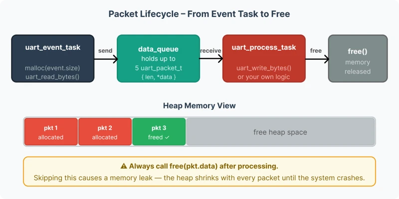
This step is critical. Since we used malloc in the event task to allocate memory for each packet, we must free it here after we’re done. If we skip this, every packet leaks memory and the heap runs out eventually.
free(pkt.data);
}
}
}Always call free(pkt.data) after processing, no matter what the application does with the data.
Here is the complete uart_process_task:
static void uart_process_task(void *pvParameters)
{
uart_packet_t pkt;
for (;;)
{
if (xQueueReceive(data_queue, &pkt, portMAX_DELAY))
{
ESP_LOGI("uart", "processing data");
uart_write_bytes(UART_NUM, pkt.data, pkt.len);
free(pkt.data);
}
}
}The diagram below shows the full lifecycle of a data packet — from the event task receiving it, to the process task handling it and freeing the memory.
Full Project Code
Here is the complete code combining everything we covered in this tutorial.
#include <stdio.h>
#include <stdlib.h>
#include <string.h>
#include "freertos/FreeRTOS.h"
#include "freertos/task.h"
#include "freertos/queue.h"
#include "driver/uart.h"
#include "esp_log.h"
#include "portmacro.h"
#define UART_NUM    UART_NUM_2
#define TXD_PIN     17
#define RXD_PIN     16
#define BUF_SIZE    (1024)
static QueueHandle_t event_queue;
typedef struct {
int len;
uint8_t *data;
} uart_packet_t;
static QueueHandle_t data_queue;
static void uart_event_task(void *pvParameters)
{
uart_event_t event;
for (;;) {
if (xQueueReceive(event_queue, (void *)&event, (TickType_t)portMAX_DELAY)) {
switch (event.type) {
case UART_DATA:
uart_packet_t pkt;
pkt.data = malloc(event.size);
if (pkt.data == NULL) {
ESP_LOGE("UART", "Malloc failed");
break;
}
ESP_LOGI("UART", "Data Event: Bytes=%d", event.size);
pkt.len = uart_read_bytes(UART_NUM, pkt.data, event.size, portMAX_DELAY);
xQueueSend(data_queue, &pkt, portMAX_DELAY);
break;
case UART_FIFO_OVF:
ESP_LOGE("uart", "hw fifo overflow");
uart_flush_input(UART_NUM);
xQueueReset(event_queue);
break;
case UART_BUFFER_FULL:
ESP_LOGI("uart", "ring buffer full");
uart_flush_input(UART_NUM);
xQueueReset(event_queue);
break;
case UART_BREAK:
ESP_LOGI("uart", "uart rx break");
break;
case UART_PARITY_ERR:
ESP_LOGI("uart", "uart parity error");
break;
case UART_FRAME_ERR:
ESP_LOGI("uart", "uart frame error");
break;
default:
ESP_LOGI("uart", "uart event type: %d", event.type);
break;
}
}
}
}
static void uart_process_task(void *pvParameters)
{
uart_packet_t pkt;
for (;;)
{
if (xQueueReceive(data_queue, &pkt, portMAX_DELAY))
{
ESP_LOGI("uart", "processing data");
uart_write_bytes(UART_NUM, pkt.data, pkt.len);
free(pkt.data);
}
}
}
void app_main(void)
{
uart_config_t uart_config = {
    .baud_rate  = 115200,
    .data_bits  = UART_DATA_8_BITS,
    .parity     = UART_PARITY_DISABLE,
    .stop_bits  = UART_STOP_BITS_1,
    .flow_ctrl  = UART_HW_FLOWCTRL_DISABLE,
    .source_clk = UART_SCLK_DEFAULT,
};
uart_driver_install(UART_NUM, BUF_SIZE * 2, BUF_SIZE, 20, &event_queue, 0);
uart_param_config(UART_NUM, &uart_config);
uart_set_pin(UART_NUM, TXD_PIN, RXD_PIN, UART_PIN_NO_CHANGE, UART_PIN_NO_CHANGE);
data_queue = xQueueCreate(5, sizeof(uart_packet_t));
xTaskCreate(uart_event_task,   "uart_event_task",   3072, NULL, 12, NULL);
xTaskCreate(uart_process_task, "uart_process_task", 2048, NULL, 11, NULL);
}Testing UART Interrupt Mode with Large Data
With the code flashed to the ESP32, we open the serial console and connect to the USB-to-TTL port. We’ll start with a small amount of data to confirm the basic setup works, then push it with large transfers to see how the system holds up.
Small Data Test
First, I sent a short string from the computer to the ESP32. The ESP32 received it and echoed it straight back. The send and receive counts matched perfectly.
The image below shows the serial console with a small string being sent and echoed back, with matching send and receive byte counts.
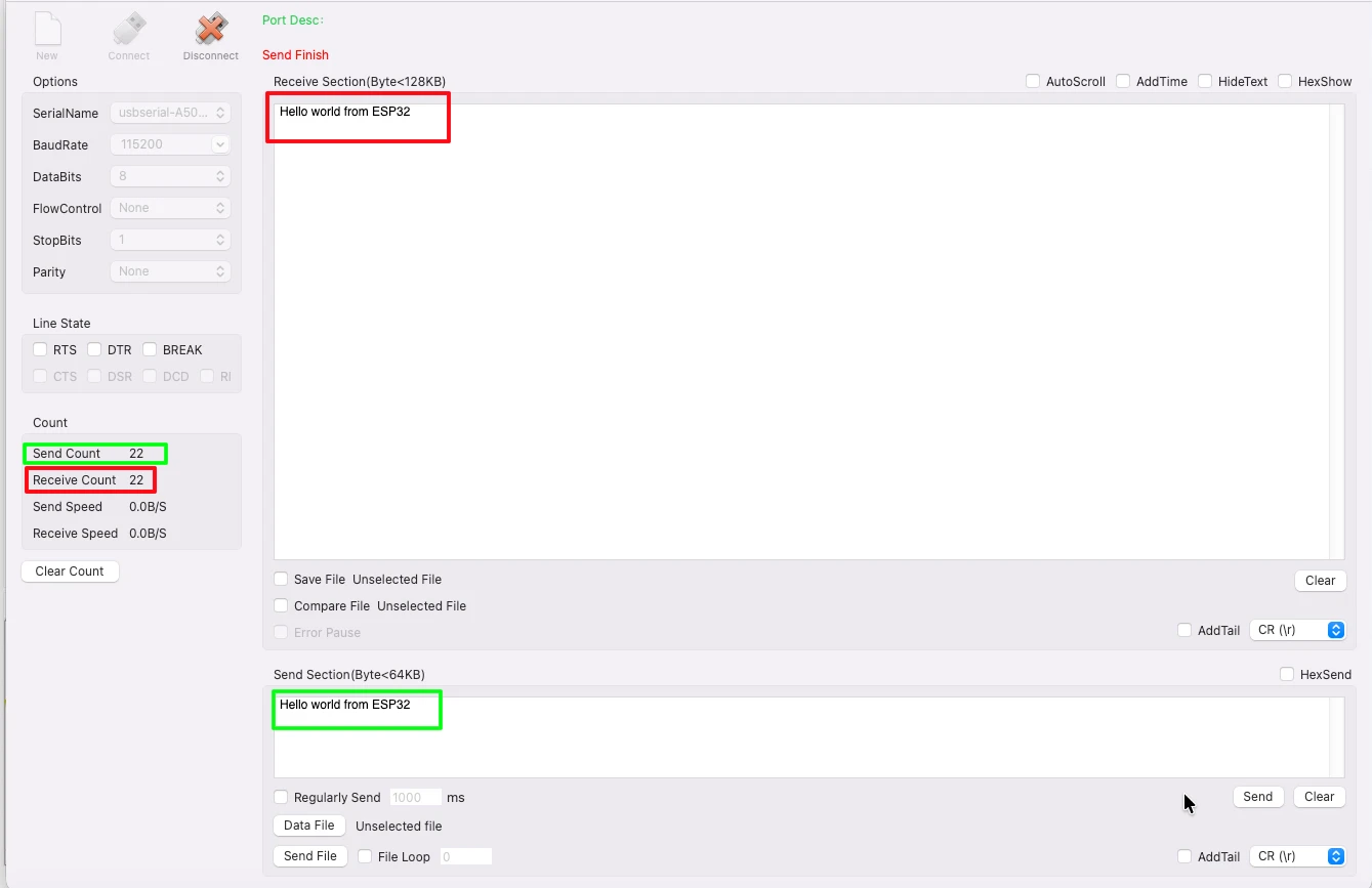
We can also see the UART event logs in the ESP32 console. Each UART_DATA event shows the number of bytes received in that event. For small data, this is usually a single event covering the entire message.
The Red box shows the data transmitted and the number of bytes transmitted by the serial console. While the Green box shows the data sent back by the ESP32.
Large Data Test (500KB)
Now let’s push the system. I am going to send 500KB of data from the computer. The ESP32 will receive it, and send it back to the computer.
The image below shows the serial console after 500KB transfer, with send and receive counts matching exactly.
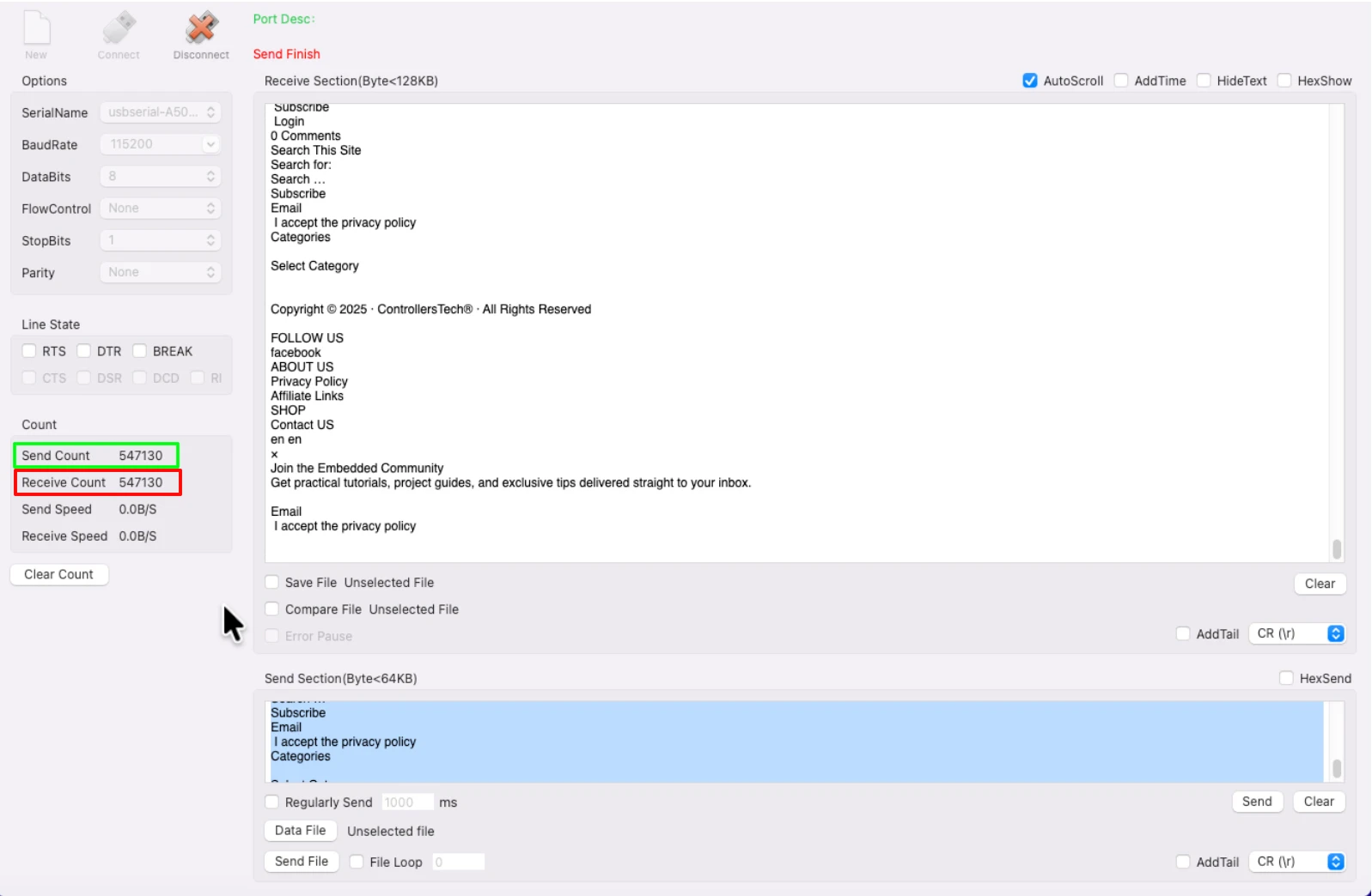
This confirms that the interrupt-based UART setup handles large and continuous data reliably. The two-task architecture — with the event task reading data fast and the process task handling it separately — is what makes this possible.
Video Tutorial
ESP32 UART Interrupt Mode – Full Demo with Large Data Test
In this video, we set up UART in interrupt mode on the ESP32 using ESP-IDF. We configure the UART driver, create the event queue, and build a two-task FreeRTOS architecture to handle incoming data without blocking the CPU.
The demo tests the setup with transfers up to 60KB of continuous data, verifying that every byte is received and echoed back correctly with zero data loss.
Watch the UART Interrupt Mode VideoConclusion
That’s how we use UART in interrupt mode on the ESP32 with ESP-IDF. By using UART events and a two-task architecture, we can receive large amounts of data reliably without blocking the CPU or losing bytes.
Here’s a quick recap of what we did:
- Used
uart_driver_installto install the driver and create the event queue automatically - Handled the
UART_DATAevent to read data from the ring buffer into a dynamically allocated packet - Passed the packet to a separate
uart_process_taskthrough thedata_queue - Freed the allocated memory after processing to prevent memory leaks
- Tested with 500KB of data and confirmed zero data loss
For most embedded applications, this approach is more than sufficient. If you ever see UART_FIFO_OVF or UART_BUFFER_FULL events during your own testing, increase the ring buffer size or lighten the workload in the process task.
Browse More ESP32 Tutorials
FreeRTOS on ESP32 (PART 4): Inter-Task Communication Explained | Queues, Semaphores, and Event Groups
ESP32 MQTT Client: Publish and Subscribe to Topics Using Espressif IDE
ESP32 ADC One‑Shot Mode Tutorial – Read Multiple Channels
How to Interface LCD1602 via I2C on ESP32 with ESP‑IDE
FreeRTOS on ESP32 (PART 1): Introduction to FreeRTOS and Task Management
FreeRTOS on ESP32 (PART 5): Software Timers and Task Notifications Explained
ESP32 SPI Tutorial Part 3: W25Q Flash Read/Write Guide
ESP32 UART Project Download

ESP32 UART Interrupt FAQs
Subscribe
Login
0 Comments
Newest
