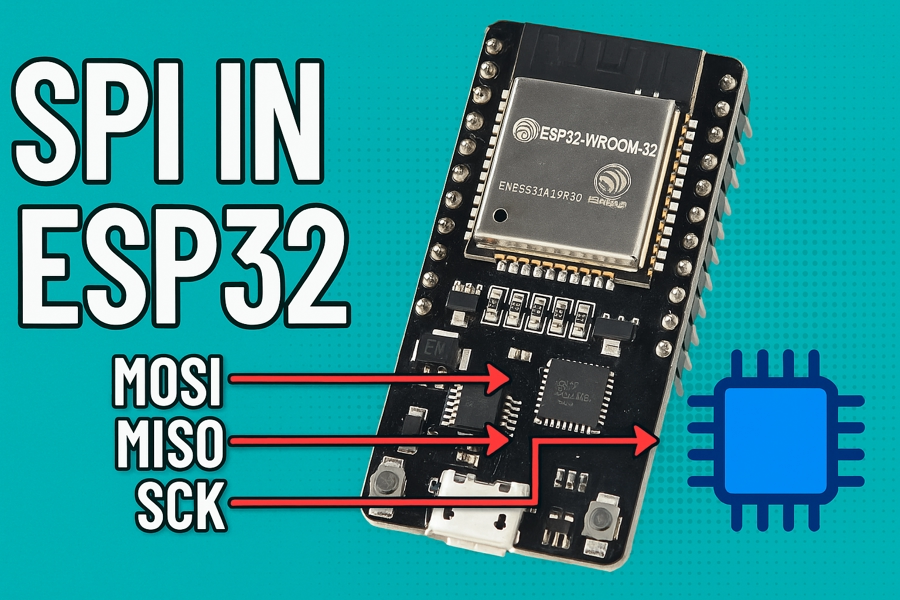
ESP32 SPI || Configure & Transmit
Discover how to set up ESP32 SPI in master mode, initialize the bus and device, and transmit data using Espressif-IDF. This step-by-step tutorial covers configuration, wiring, and includes a downloadable project at the end.

This is the 5th tutorial in the ESP32 series using the espressif-IDF and 1st in a mini series covering SPI peripheral of ESP32. We will cover the SPI peripheral in 3 tutorial series, but we will only focus on ESP32 as the SPI master. We will see how to configure the SPI bus, how to transmit the data to the slave device and how to read the data from the slave device.
VIDEO TUTORIAL
You can check the video to see the complete explanation and working of this project.
Check out the Video Below
Introducing the SPI peripheral in ESP32
The ESP32 microcontroller features multiple SPI (Serial Peripheral Interface) peripherals, which are versatile and efficient for high-speed communication with a wide range of devices such as sensors, displays, memory chips, and other microcontrollers. It supports full-duplex data transfers and can operate in both master and slave modes. The SPI drivers in the ESP-IDF (Espressif IoT Development Framework) provide flexible APIs for configuration, queuing transactions, and DMA-based transfers for optimal performance.
Some important features of SPI peripherals are:
- Flexible Communication Modes: Supports master and slave modes, full-duplex and half-duplex communication, and both 3-wire and 4-wire SPI.
- High-Speed Data Transfer: Operates at clock speeds up to 80 MHz with support for DMA and FIFO buffers for efficient data handling.
- Multiple SPI Channels: Includes up to 4 SPI peripherals (SPI0–SPI3), with HSPI and VSPI available for general use.
- Advanced Configuration: Offers configurable clock polarity/phase (CPOL/CPHA), auto chip-select control, and ESP-IDF APIs for queue-based asynchronous transfers.
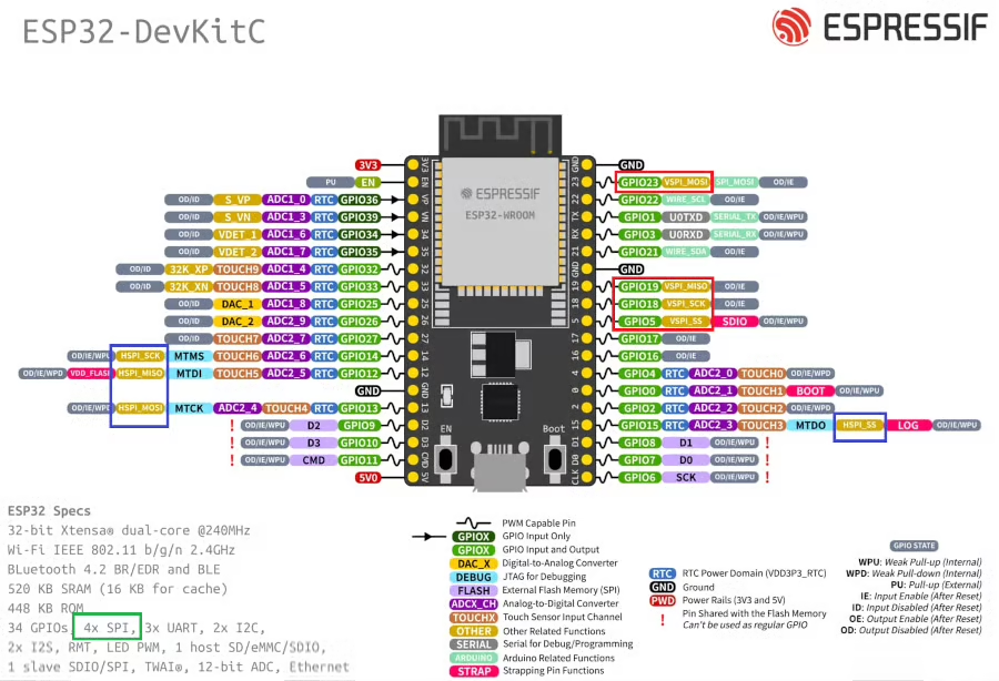
I am using the ESP32 wroom Development board with 38 pins. Below is the image showing the pinout and available SPI instances ion this board.
The ESP32 microcontroller has four Serial Peripheral Interface (SPI) ports: SPI0, SPI1, HSPI (SPI2), and VSPI (SPI3).
- SPI0 and SPI1: Used internally to communicate with the ESP32’s flash memory. These ports share the same SPI bus signals, and an arbiter determines which can access the bus.
- HSPI (SPI2) and VSPI (SPI3): General purpose SPI drivers that users can access. These ports have independent bus signals, and each bus can drive up to three SPI slaves.
The image above shows the pins availability for the VSPI (Red Box) and HSPI (Blue Box). We can use either of these instances to avoid any conflict with the internal flash memory.
THE CODE
In this tutorial I am not connecting any slave device to the SPI bus. Instead I will capture the transmitted data on a scope so that we can confirm if the master device is transmitting correctly.
SPI Initialization
The SPI in ESP32 is configured in 2 steps.
- First we need to configure the SPI bus, which is common for all the SPI instances we use.
- Then add a device to the bus. We can transmit the data to/from this device we add.
Configure the SPI bus
#define ESP_HOST VSPI_HOST
esp_err_t ESP_ERR;
spi_device_handle_t spi_handle;

spi_bus_config_t buscfg = {
    .mosi_io_num = 23,
    .miso_io_num = 19,
    .sclk_io_num = 18,
    .quadwp_io_num = -1,
    .quadhd_io_num = -1
};
ESP_ERR = spi_bus_initialize(ESP_HOST, &buscfg, SPI_DMA_CH_AUTO);
assert(ESP_ERR == ESP_OK);The structure buscfg stores all the important information about the SPI bus. The members of this structure are mentioned below:
- mosi_io_num is the GPIO for the MOSI (Master Out Slave In). As per the pinout shown above, I am using the GPIO 23 for the MOSI.
- miso_io_num is the GPIO for the MISO (Master In Slave Out). As per the pinout, I am using the GPIO 19 for the MISO.
- sclk_io_num is the GPIO for the CLK (SPI Clock). I am using GPIO 18 for the CLK.
- The quadwp are used in the Quad SPI Mode. Since we are not using the Quad SPI, we will set them to -1.
The function spi_bus_initialize is used to initialize the SPI bus. The parameters of this function are as follows:
- @host_id : SPI peripheral that controls this bus. In this case I am using the VSPI_HOST.
- @bus_config : Pointer to a spi_bus_config_t struct specifying how the host should be initialized. We have already defined it.
- @dma_chan : Selecting a DMA channel for an SPI bus allows transactions on the bus with size only limited by the amount of internal memory.
- Selecting SPI_DMA_DISABLED limits the size of transactions.
- Set to SPI_DMA_DISABLED if only the SPI flash uses this bus.
- Set to SPI_DMA_CH_AUTO to let the driver to allocate the DMA channel.
This function returns ESP_OK on success.
Configuring the SPI Device
Now that the bus is configured, we will add a SPI device to this bus. Below is the configuration for the SPI device.
spi_device_interface_config_t devcfg = {
    .command_bits = 0,
    .address_bits = 0,
    .dummy_bits = 0,
    .clock_speed_hz = 2000000,
    .duty_cycle_pos = 128,      //50% duty cycle
    .mode = 0,
    .spics_io_num = GPIO_CS,
    .queue_size = 3
};

ESP_ERR = spi_bus_add_device(ESP_HOST, &devcfg, &spi_handle);
assert(ESP_ERR == ESP_OK);The structure devcfg stores all the information about the device. The members of this structure are explained below:
- We will talk about the command, address and dummy bits in the upcoming tutorials. These parameters are mainly used while reading the data from the slave, so let’s not worry about them right now.
- clock_speed_hz is the SPI clock frequency in Hz. I have set it to 2MHz.
- duty_cycle_pos is the duty cycle for the SPI clock. The duty_cycle_pos range varies from 1 to 256, therefore setting it at 128 represents 50% duty cycle.
- mode is the SPI mode. There are 4 types of SPI modes depending upon the polarity and phase of the clock:
- Mode 0: CPOL = 0, CPHA = 0
- Mode 1: CPOL = 0, CPHA = 1
- Mode 2: CPOL = 1, CPHA = 0
- Mode 3: CPOL = 1, CPHA = 1
- spics_io_num is the GPIO for the CS (Chip Select / Slave Select). As per the pinout I am using GPIO 5 for the CS.
- queue_size is the number of SPI transaction that can be sent to the queue at the same time. Basically the queue can store 3 transactions.
The function spi_bus_add_device
is used to add the above configured device to the SPI bus. The parameters of this function are as follows:
- @host_id : SPI peripheral that controls this bus. In this case I am using the VSPI_HOST.
- @dev_config : Pointer to a spi_device_interface_config_t struct specifying configuration for the SPI slave device.
- @handle : Handle for the device on a SPI bus. I have defined it globally as spi_handle, so that we can use it in other functions as well.
SPI Init function
Below is the SPI initialization function, which is a combination of what we discussed above.
#define GPIO_MOSI           23
#define GPIO_MISO           19
#define GPIO_SCLK           18
#define GPIO_CS             5

#define ESP_HOST VSPI_HOST
esp_err_t ESP_ERR;
spi_device_handle_t spi_handle;

void SPI_Init (void)
{
    //Configuration for the SPI bus
    spi_bus_config_t buscfg = {
        .mosi_io_num = GPIO_MOSI,
        .miso_io_num = GPIO_MISO,
        .sclk_io_num = GPIO_SCLK,
        .quadwp_io_num = -1,
        .quadhd_io_num = -1
    };

    //Configuration for the SPI device on the other side of the bus
    spi_device_interface_config_t devcfg = {
        .command_bits = 0,
        .address_bits = 0,
        .dummy_bits = 0,
        .clock_speed_hz = 2000000,
        .duty_cycle_pos = 128,      //50% duty cycle
        .mode = 0,
        .spics_io_num = GPIO_CS,
        .queue_size = 3
    };

    //Initialize the SPI bus and add the device we want to send stuff to.
    ESP_ERR = spi_bus_initialize(ESP_HOST, &buscfg, SPI_DMA_CH_AUTO);
    assert(ESP_ERR == ESP_OK);
    ESP_ERR = spi_bus_add_device(ESP_HOST, &devcfg, &spi_handle);
    assert(ESP_ERR == ESP_OK);
}Transmit the Data
Just like the initialization, we will write a new function to transmit the data over the SPI.
void spi_transmit (uint8_t *data, int bytes)
{The parameters of the spi_transmit function are as follows:
- @data is the pointer to the data array, that we want to transmit.
- @bytes is the number of data bytes to be transmitted.
Inside this function we first need to define a SPI Transaction structure.
spi_transaction_t trans;
memset(&trans, 0, sizeof(spi_transaction_t));The SPI Transaction structure should hold all the information about the transaction we want to perform on the SPI bus. It holds information like the transmit and receiving buffers, the size of the data to be transmitted or received, etc. You can read about this structure in detail in the ESP docs.
Since we are only transmitting the data, we just need to focus on the members like tx_buffer and the length.
trans.tx_buffer = data;
trans.length = bytes*8;- tx_buffer is the pointer to the buffer that we want to transmit over the SPI. Here we already have the buffer (data) in the parameter of the function.
- length is the total data length in bits. It includes the length of the data to be transmitted and the data to be received as well. The parameter bytes is the number of data bytes we want to transmit, therefore we will convert it to bits and then pass it to the length.
After preparing the transaction, we will send it via the SPI.
if (spi_device_transmit(spi_handle, &trans) != ESP_OK) // spi_device_polling_transmit(spi_handle, &trans)
{
printf("writing error\n");
}
}The function spi_device_transmit queues the transaction to the SPI queue and then waits for the transfer to complete. You can also use other functions like spi_device_polling_transmit to do the same.
Combining the above functions, the final spi_transmit function is shown below.
void spi_transmit (uint8_t *data, int bytes)
{
	spi_transaction_t trans;
	memset(&trans, 0, sizeof(spi_transaction_t));
	trans.tx_buffer = data;
	trans.length = bytes*8;
if (spi_device_transmit(spi_handle, &trans) != ESP_OK)
{
printf("writing error\n");
}
}The main function
Inside the main function, we will simply initialize the SPI and then keep transmitting the data every second.
char *data = "Hello world from ESP using SPI";
void app_main(void)
{
    SPI_Init();
    while (1)
    {
	spi_transmit((uint8_t *)data, strlen(data));
	sleep(1);
    }
}Here we will first initialize the SPI in the main function. Then the function spi_transmit will be called in the while loop, to transmit the data every second.
spi_transmit function takes the parameter as the pointer to the uint8_t, hence we need to typecast the data pointer.
RESULT
As I mentioned earlier I am not connecting any slave device in today’s tutorial. Instead I will capture the data on the scope. Unlike I2C, the SPI does not require any kind of handshake, so operating the master without any slave is not a problem.
Below is the image showing the data captured on the logic analyzer.
You can see the SPI clock is at 2MHz with 50% Duty Cycle. This is the same as what we configured the device with.
The CS line automatically goes low before the data transmission begins, this is to enable the slave device. The line goes high right after the transaction is finished.
Note that the data captured by the analyzer is same as what we transmitted.
PROJECT DOWNLOAD
Info
You can help with the development by DONATING Below.
To download the project, click the DOWNLOAD button.


