Home ▸ STM32 Tutorials ▸ STM32 HAL ▸
Updated On: January 16, 2026
How to interface HCSR04 sensor with STM32
The HC-SR04 ultrasonic sensor is one of the most popular distance-measuring sensors used in embedded systems and robotics. It can measure distances accurately by sending ultrasonic waves and calculating the time taken for the echo to return. When paired with an STM32 microcontroller, it becomes a powerful tool for obstacle detection, automation projects, or simple robotics applications.
In this tutorial, we will interface the HC-SR04 sensor with an STM32 microcontroller step by step. We will understand how the sensor works, configure the necessary GPIO pins in STM32CubeMX, and write HAL code to trigger the sensor and read the echo pulse to calculate distance. By the end of this tutorial, you will be able to measure distances reliably and use this sensor in your own projects.
Prerequisite:
This tutorial uses Input Capture feature of the STM32 Timer to read the pulse sent by the HC-SR04. You should take a look at the following tutorial before continuing with this one.
What is HC-SR04 Ultrasonic Sensor?
The HC-SR04 Ultrasonic Sensor is a popular distance-measuring module used with Arduino. It works by sending sound waves and measuring how long they take to bounce back. Because of this simple working method, it becomes very useful in many projects like obstacle detection, automatic lights, and water-level monitoring.
The sensor is reliable, low-cost, and easy to connect. In the sections below, you will learn how the sensor works, what each pin does, and what voltage it needs.
How the HC-SR04 Ultrasonic Sensor Works
The working principle of the HC-SR04 is simple yet very effective. The sensor emits an ultrasonic wave at 40 kHz, which travels until it hits an obstacle and then reflects back to the sensor. By measuring the time it takes for the echo to return, we can calculate the distance between the sensor and the object using the speed of sound.
Here’s how it works step by step:
- Keep the Trig pin HIGH for at least 10 microseconds.
- The module sends an 8-cycle burst of 40 kHz ultrasound.
- If the sound wave hits an object and returns, the Echo pin goes HIGH.
- The width of this HIGH pulse is proportional to the distance of the object.
The distance can be calculated using:
Distance = (Pulse Duration × Speed of Sound) / 2Or using simplified formulas:
Distance (cm) = Pulse Duration (µs) / 58Distance (inch) = Pulse Duration (µs) / 148
It is recommended to wait at least 60 ms before starting the next measurement to ensure accurate readings.
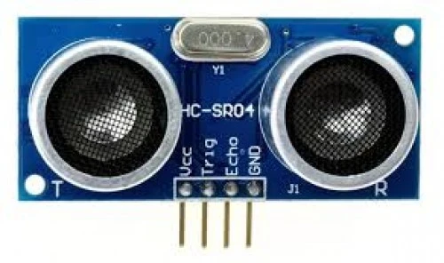
HC-SR04 Pinout Explanation
The sensor has four pins, and each one has a specific role. The image below shows the pinout of HC-SR04.
The pin functions are explained in the table below.
| Pin Name | Direction | Description |
|---|---|---|
| VCC | Input to the sensor | Powers the sensor |
| TRIG | Input to the sensor | Receives trigger pulse from Arduino |
| ECHO | Output from the sensor | Sends pulse duration back to Arduino |
| GND | Input to the sensor | Ground reference |
Voltage and Timing Requirements
The HC-SR04 needs the following voltage and timing values to work correctly:
- Operating Voltage: 5V
- Trigger Pulse Width: Minimum 10 microseconds
- Echo Output Voltage: 5V
- Measuring Range: 2 cm to 400 cm
- Accuracy: Around ±3 mm
- Ultrasonic Frequency: 40 kHz
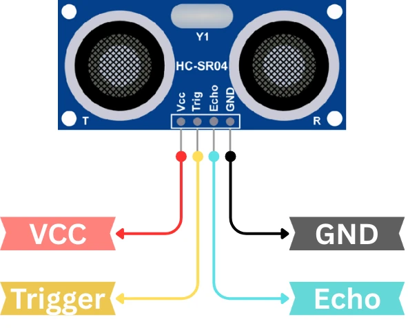
Wiring HC-SR04 with STM32
The image below shows the wiring connection between STM32 and HC-SR04 ultrasonic sensor.
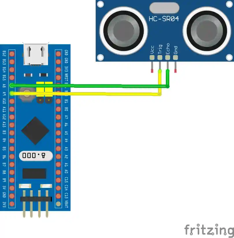
The Trig pin from the sensor is connected to the pin PA9. Whereas, the Echo pin from the sensor is connected to PA8, the TIM1 CH1 pin.
The sensor is powered with 5V from the STM32 board itself.
STM32 CubeMX Configuration
Let’s start with configuring the project in STM32CubeMX first.
Timer Configuration
I am going to use the Input capture to read the pulse from the sensor. Therefore we must configure the timer in the input capture mode.
The image below shows the timer configuration for input capture mode.
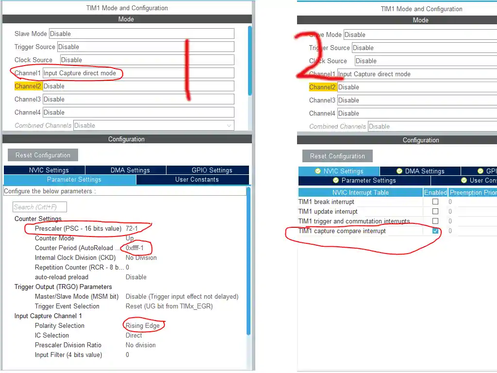
I am using Timer 1 for this purpose.
- I have selected the Input Capture Direct Mode.
- Prescalar is set to 72 -> This will divide theAPB clock by 72, and bring the timer clock to 1 MHz. It is necessary because the HC-SR04 sends the signal in microseconds.
- ARR is set to 0xffff -> I have selected is as maximum as possible. This basically sets the limit, upto which we can count in microseconds.
- Also make sure the TIMx Capture Compare interrupt is enabled. You can enable the Global interrupt also, if you don’t see this option
Pin Configuration
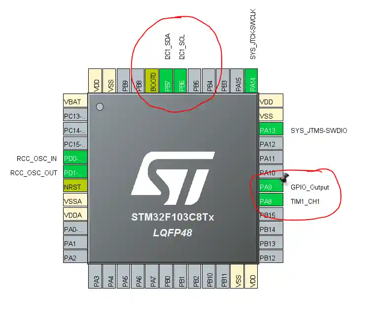
- Pin PA8 -> is automatically selected as TIM1_CH1 pin. We will use it as the ECHO Pin
- Pin PA9 -> will be use as TRIG Pin, so select it as the output.
I2C Configuration
I am using the LCD1602 to display the current Time and Date. The LCD is connected using the PCF8574 I2C extender. Below is the image showing the I2C configuration.
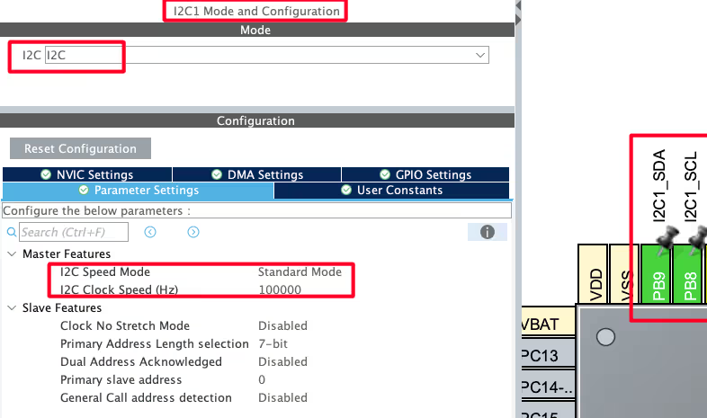
I am using the I2C1 to connect the LCD. The I2C is configured in the standard mode with the clock speed set to 100KHz. The pins PB8 and PB9 are configured as the SCL and SDA pins.
We have already covered how to interface the LCD via I2C with STM32. You can check out the tutorial for more details.
STM32 Code to interface HC-SR04
Microsecond Delay
We need delay in microseconds to send a trigger signal to the sensor. Therefore we will first create a function to generate delay in microseconds.
void delay (uint16_t time)
{
	__HAL_TIM_SET_COUNTER(&htim1, 0);
	while (__HAL_TIM_GET_COUNTER (&htim1) < time);
}Inside this function, we simply reset the TIM1 counter, and wait for it to reach the desired value. Since the TIM1 is configured to run at 1MHz, each count of the counter takes 1us.
This function gives us the desired delay in microseconds.
Input Capture Callback
We have configured the Timer Input capture mode to read the pulse sent by the HC-SR04. The timer interrupt is enabled, hence, when an interrupt is triggered by an incoming pulse, the HAL_TIM_IC_CaptureCallback will be called by the HAL.
The function below shows how we handle the pusles.
void HAL_TIM_IC_CaptureCallback(TIM_HandleTypeDef *htim)
{
	if (htim->Channel == HAL_TIM_ACTIVE_CHANNEL_1)  // if the interrupt source is channel1
	{
		if (Is_First_Captured==0) // if the first value is not captured
		{
			IC_Val1 = HAL_TIM_ReadCapturedValue(htim, TIM_CHANNEL_1); // read the first value
			Is_First_Captured = 1;  // set the first captured as true
			// Now change the polarity to falling edge
			__HAL_TIM_SET_CAPTUREPOLARITY(htim, TIM_CHANNEL_1, TIM_INPUTCHANNELPOLARITY_FALLING);
		}

		else if (Is_First_Captured==1)   // if the first is already captured
		{
			IC_Val2 = HAL_TIM_ReadCapturedValue(htim, TIM_CHANNEL_1);  // read second value
			__HAL_TIM_SET_COUNTER(htim, 0);  // reset the counter

			if (IC_Val2 > IC_Val1)
			{
				Difference = IC_Val2-IC_Val1;
			}

			else if (IC_Val1 > IC_Val2)
			{
				Difference = (0xffff - IC_Val1) + IC_Val2;
			}

			Distance = Difference * .034/2;
			Is_First_Captured = 0; // set it back to false

			// set polarity to rising edge
			__HAL_TIM_SET_CAPTUREPOLARITY(htim, TIM_CHANNEL_1, TIM_INPUTCHANNELPOLARITY_RISING);
			__HAL_TIM_DISABLE_IT(&htim1, TIM_IT_CC1);
		}
	}
}Explanation:
When a rising edge occurs (Is_First_Captured == 0):
- It records the first timer value (
IC_Val1). - Sets a flag to indicate the first capture is done.
- Changes the input polarity to detect the falling edge next.
When the falling edge occurs (Is_First_Captured == 1):
- It records the second timer value (
IC_Val2). - Calculates the time difference between the two edges, accounting for timer overflow.
- Converts this time difference to distance using the speed of sound formula.
- Resets the flag and sets the polarity back to rising edge for the next measurement.
- Disables the interrupt until re-enabled elsewhere.
HCSR04_Read Function
The function HCSR04_Read is called whenever we want to read the data from the sensor.
void HCSR04_Read (void)
{
	HAL_GPIO_WritePin(TRIG_PORT, TRIG_PIN, GPIO_PIN_SET);  // pull the TRIG pin HIGH
	delay(10);  // wait for 10 us
	HAL_GPIO_WritePin(TRIG_PORT, TRIG_PIN, GPIO_PIN_RESET);  // pull the TRIG pin low

	__HAL_TIM_ENABLE_IT(&htim1, TIM_IT_CC1);
}- It will pull the TRIG Pin HIGH for 10 microseconds, and then pull it LOW.
- This will force the sensor to start the measurement, and the sensor will pull the ECHO Pin HIGH for the respective amount of time
- To measure this time, we will enable the Timer interrupt, so that we can capture this Rising and falling edges
Result of HC-SR04 on the LCD
The video below shows the complete working. The distance calculated is printed on the LCD1602 display.
You can check out the detailed working in the video attached below.
VIDEO TUTORIAL
STM32 HC-SR04 Ultrasonic Sensor Tutorial Video
In this tutorial, we show how to interface the HC-SR04 ultrasonic sensor with an STM32 microcontroller. You’ll learn the wiring, configure the GPIO pins in STM32CubeMX, and write HAL code to trigger the sensor, measure the echo pulse, and calculate distance accurately. A step-by-step video walkthrough is included to help you follow along and understand each part of the process clearly.
Watch the HC-SR04 Video TutorialConclusion
In this tutorial, we covered how to interface the HC-SR04 ultrasonic sensor with an STM32 microcontroller. We explained the working principle of the sensor, configured the GPIO pins, and wrote the code to trigger the sensor and calculate distance from the echo pulse. You also learned how to use STM32CubeMX and HAL functions to implement the measurement accurately.
Using the HC-SR04 with STM32 is extremely useful in a wide range of projects, from simple distance measurement to obstacle detection in robotics. Once you understand the basic working and timing logic, you can combine the sensor with displays, alarms, or motor control to create practical applications. The concepts here also serve as a foundation for working with other timing-based sensors.
Checkout More STM32 Sensor Tutorials
How to interface MPU6050 (GY-521) with STM32
STM32 DHT22 Temperature & Humidity Sensor with HAL
GP2Y0A41SK0F STM32 ADC Distance Measurement Guide
Interfacing ADXL345 Accelerometer with STM32 via I2C
Interface AHT20 Sensor with STM32 Using I2C
How to interface DS18B20 with STM32
Interface BMP180 with STM32
STM32 HC-SR04 Project Download
STM32 HC-SR04 FAQs


Hi, im using the f446ret6 and the lcd displays “distance, then displays numbers and keeps displaying different numbers without reseting to “distance 23” for example, it displays “distance 0 cm8 cm6 cm9 cm2 cm5 cm6 cm9″and so on it doesnt display values larger than 10 either, ever. Thank you for the tutorial.
is that ok the fact that I can’t measure distances less than 8 cm? I use a US-015 which has the measure range of 2-400cm?
I’m doing it with uart but i cannot display it through UART can you help me?
void HAL_TIM_IC_CaptureCallback(TIM_HandleTypeDef *htim)
{
if (htim->Channel == HAL_TIM_ACTIVE_CHANNEL_1) // if the interrupt source is channel1
{
if (Is_First_Captured==0) // if the first value is not captured
{
IC_Val1 = HAL_TIM_ReadCapturedValue(htim, TIM_CHANNEL_1); // read the first value
Is_First_Captured = 1; // set the first captured as true
// Now change the polarity to falling edge
__HAL_TIM_SET_CAPTUREPOLARITY(htim, TIM_CHANNEL_1, TIM_INPUTCHANNELPOLARITY_FALLING);
}
else if (Is_First_Captured==1) // if the first is already captured
{
IC_Val2 = HAL_TIM_ReadCapturedValue(htim, TIM_CHANNEL_1); // read second value
__HAL_TIM_SET_COUNTER(htim, 0); // reset the counter
if (IC_Val2 > IC_Val1)
{
Difference = IC_Val2-IC_Val1;
}
else if (IC_Val1 > IC_Val2)
{
Difference = (0xffff – IC_Val1) + IC_Val2;
}
Distance = Difference * .034/2;
HAL_UART_Transmit_DMA(&huart4, (uint8_t *)&c, sizeof(c));
Is_First_Captured = 0; // set it back to false
// set polarity to rising edge
__HAL_TIM_SET_CAPTUREPOLARITY(htim, TIM_CHANNEL_1, TIM_INPUTCHANNELPOLARITY_RISING);
__HAL_TIM_DISABLE_IT(&htim1, TIM_IT_CC1);
}
}
}
Hi
can you help me with using 3 sensors with this code?
thank you so much
can you explain for me ?
else if (IC_Val2<IC_Val1)
{
T=(0xffff-IC_Val1)+IC_Val2;
}
why when IC_Val2<IC_Val1 then we have T= oxffff-Ic_VAl1)+IC_Val2 ?
when overflowing occurs we must handle it to get correct value. those lines written for that purpose.
Thanks for the useful information!
However, in your codes there is some error.
Trigger pin should be 9 instead of 8.
ok. I will correct it and reupload. Thanks for informing
I think it will be easier
void HAL_TIM_IC_CaptureCallback(TIM_HandleTypeDef *htim)
{
if (htim->Channel == HAL_TIM_ACTIVE_CHANNEL_1) // if the interrupt source is channel1
{
if (Is_First_Captured==0) // if the first value is not captured
{
TIM2->CNT = 0;
Is_First_Captured = 1; // set the first captured as true
// Now change the polarity to falling edge
__HAL_TIM_SET_CAPTUREPOLARITY(htim, TIM_CHANNEL_1, TIM_INPUTCHANNELPOLARITY_FALLING);
}
else if (Is_First_Captured==1) // if the first is already captured
{
Difference = HAL_TIM_ReadCapturedValue(htim, TIM_CHANNEL_1); // read second value
Distance = Difference * .034/2;
Is_First_Captured = 0; // set it back to false
// set polarity to rising edge
__HAL_TIM_SET_CAPTUREPOLARITY(htim, TIM_CHANNEL_1, TIM_INPUTCHANNELPOLARITY_RISING);
}
}
}
Exactly
Im using your code but it is geting stuck at the while loop of: local_time++
The code just keep adding up on the local_time value.
I made the Local_time an integer. if i make it anything else it wont add up and when i just use the code it tells me: error: ‘local_time’ undeclared
help is much appreciated, any ideas?
I am working on better approach towards this problem.
If you want to test the code, come to this channel below
https://t.me/controllerstechdiscuss
tips: Check voltage before using HC-SR04. I use stm32f103c8t6 connecting st-link(3.3V). I thought that the 5V pin should output 5V(in fact <3V) and connect HC-SR04 VCC to it. The result is that the return value of function hcsr04_read() is always small values(2, 3 etc). Use microUSB as power of stm32f103c8t6 instead, which make the 5V pin 5V.
spend lots of time checking my code but finally a voltmeter solved the problem QAQ
Thank you so much, I fell into the same trap, even though I knew 5V pin doesn’t output 5V(T-T).
* return __HAL_TIM_GET_COUNTER(&htim1);
sorry for my google translate english. Your code contains bugs and incorrectly measures echo time. I did a little with the oscilloscope and found a problem.
Of course, not using interrupts is a bad option, but since the poll is done right.
uint32_t hcsr04_read(void) {
HAL_GPIO_WritePin(GPIOA, GPIO_PIN_1, GPIO_PIN_RESET); // pull the TRIG pin HIGH
delay(2); // wait for 2 us
HAL_GPIO_WritePin(GPIOA, GPIO_PIN_1, GPIO_PIN_SET); // pull the TRIG pin HIGH
delay(10); // wait for 10 us
HAL_GPIO_WritePin(GPIOA, GPIO_PIN_1, GPIO_PIN_RESET); // pull the TRIG pin low
// read the time for which the pin is high
while (!HAL_GPIO_ReadPin(GPIOA, GPIO_PIN_4))
; // wait for the ECHO pin to go high
__HAL_TIM_SET_COUNTER(&htim1, 0);
while (HAL_GPIO_ReadPin(GPIOA, GPIO_PIN_4))
; // wait for the ECHO pin to go high
return __HAL_TIM_GET_COUNTER(&htim2);
}
I don’t know why but there are a lot of complaints recently on this. when I wrote this, I got the results pretty accurate.
Seems like it needs the modifications. I will try to use Input capture to measure the pulse width and then calculate the distance.
Thanks for informing. I will update this soon
stm32f103c8t6
the error is approximately the same 1000ms (oscilloscope control)> 400ms according to stm32
while (HAL_GPIO_ReadPin(GPIOA, GPIO_PIN_4))    // while the pin is high
	 {
		local_time++;   // measure time for which the pin is high
		delay
void delay (uint32_t us) { __HAL_TIM_SET_COUNTER(&htim1, 0); while ((__HAL_TIM_GET_COUNTER(&htim1))<us); }there is too much overhead.
can u share circuit diagram on proteus ?
Hi. Greetings from Panama. I have tried to replicate the code to read 8 hc-sr04 sensors but the distance measurements are very inaccurate. Instead of measuring 60 cm, it gives readings of 20 cm and so … What could it be?
Timing could be the issue. Check the microsecond delay part properly.
Thanks for answering. I already checked the timer part. I followed the steps in the tutorial you posted about timers (How to create delay in nano / micro seconds using timers in stm32) and nothing changed. Curiously, when modifying the equation to transform from microseconds to centimeters, thus leaving it “microseconds * 0.034”, the distances are calculated correctly, but I don’t know why it is no longer necessary to divide by 2.
Another query, I want to send the information of these 8 HC-SR04 sensors, an MPU6050 and two encoders through I2C communication to a raspberry pi 3b +, What tutorial of those you have published can serve as a guide? thanks for your help.
Thank you
Hi, file “stm32f4xx_hal.h” in zipfile is encrypted, could you upload correct version ?
The file is fine. There is no encryption. It have a Drivers.7z file, which you need to extract. I did that to reduce the size.
Although, if you are creating project from scratch, you don’t need that. Your IDE will create that for you.
the sensor seems to work fine but it keeps on getting the answer 2!
(for “local time’)
and I cant see why .. I doubled checked the pin config like in the video and moreover when I disconnect the sensor at mid_run the “local time” var is reached zero and halt – witch means that 2 is actually the same answer it gets in any time .. any ideas?
What’s “local time” ?
its the same var you wrote in your code which measures the time ( in every 1us) between the echo-response ( line 20 ) .. the problem is that this var get the value of 2 always.. I also tried to change the sensor yet the result remains the same.
its seems like nonmater what I do, my echo window remains one US .
What controller are u using ? Did you test the microsecond delay ? If that doesn’t work, nothing will.
im using bluepill – stm32f103c8
i used your microsecond- and just now i have measured the DWT->CYCCNT space within the window and got the same result … am I missing something in your tutorial?
send me you code.zip at [email protected]
thank! I just transferred it, please send me an e-mail if ther is a problem 🙂
I could compiled the download source code and appeared the undefined errors about lcd_init,lcd_send_cmd,lcd_send_data and DWT_Delay_Init
Start ur project from scratch and than later include these files in the project.
thanks for this toturial i need it