
Home ▸ Arduino ▸ Displays & Interfaces ▸
Updated On: February 5, 2026
Interface TM1637 4-Digit 7-Segment Display with Arduino
The TM1637 4-digit 7-segment display is one of the easiest numeric displays you can use with Arduino. It needs only two pins and shows numbers, timers, counters, and even real-time clock data. Because of its low price and simple wiring, it is very popular in Arduino projects.
In this tutorial, you will learn how to interface the TM1637 module with Arduino, how each display function works, and how to write clean and simple code examples. Each function includes short explanations for easy understanding.
You will also build multiple projects, including a real time clock using the DS3231 module. This final project displays the current time on the TM1637 display.
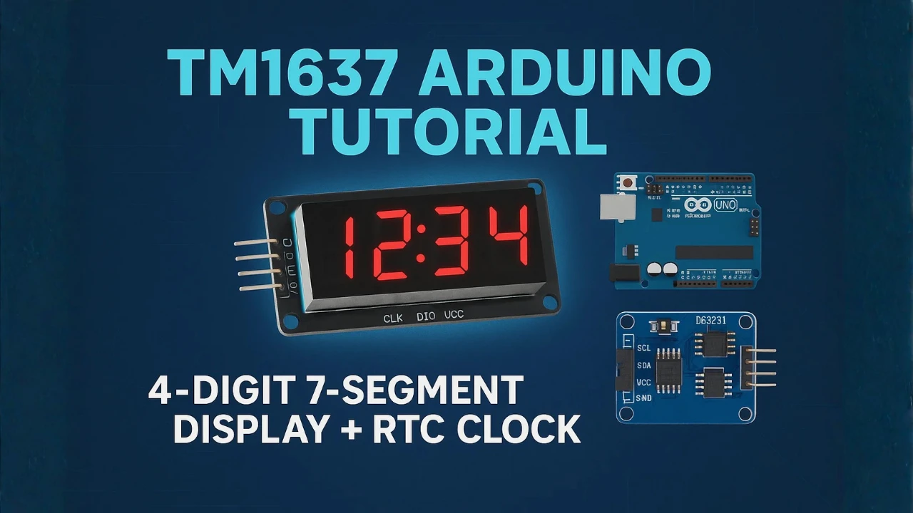
Table Of Contents
What is the TM1637 4-Digit 7-Segment Display?
The TM1637 module is a widely used 4-digit 7-segment display. It is perfect for showing numbers, counters, timers, clocks, and sensor values. This display works on a simple 2-wire interface, which makes it ideal for beginners. In this part, we will look at its features, pinout, and how communication works.
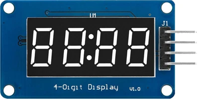
Features of TM1637 Display
- It has 4 digits, each made of 7 segments plus a decimal point.
- Uses a TM1637 driver IC, which reduces the number of required pins.
- Works with only two control pins: CLK and DIO.
- Supports adjustable brightness levels.
- Operates on 5V, which is perfect for Arduino boards.
- Displays numbers, characters, and custom segment patterns.
- Easy to program using the TM1637Display library.
Pinout of TM1637 Module
The TM1637 module usually has 4 pins:
| Pin | Name | Description |
|---|---|---|
| 1 | VCC | Power supply (5V) |
| 2 | GND | Ground |
| 3 | DIO | Data input/output |
| 4 | CLK | Clock signal |
VCC and GND power the display.
DIO and CLK handle the communication between Arduino and the TM1637 IC.
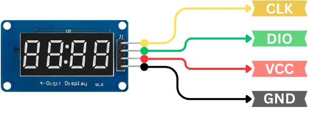
These four pins make the module simple to connect and easy to understand.
How the TM1637 Communication Works
The TM1637 uses a two-wire serial protocol, similar to I2C but not the same.
Here’s how it works:
- CLK pin sends the timing/clock pulses.
- DIO pin transfers data to and from the module.
- Arduino sends commands to control brightness, segments, and digits.
- The TM1637 IC handles the heavy work of driving the display.
This 2-wire system makes the display fast, stable, and easy to use in small microcontroller projects.
Components Required for This Arduino TM1637 Tutorial
List of Components
You will need the following items:
- Arduino board (Uno, Nano, Mega, Leonardo, etc.)
- TM1637 4-digit 7-segment display module
- Jumper wires (male-to-female or male-to-male depending on your setup)
- Breadboard (optional but helps keep wiring clean)
For the real-time clock project, you also need:
- DS3231 RTC module
- Extra jumper wires
These few components are enough to build all the examples, from simple counters to a complete real-time clock.
Arduino Board Compatibility
The TM1637 module works with almost every Arduino board.
Some popular and fully compatible options are:
- Arduino Uno
- Arduino Nano
- Arduino Mega 2560
- Arduino Leonardo
- Arduino Pro Mini
Since the display uses only 2 digital pins, it is also suitable for projects where I/O pins are limited. You can use 3.3V or 5V logic boards, but 5V boards work best for maximum brightness and stability.
Circuit Diagram: Arduino with TM1637 Display
Wiring the TM1637 module is very simple because it uses only two data pins: DIO and CLK. These pins connect directly to the Arduino’s digital pins. Follow the connection guide below to set up your display correctly.
The image below shows the wiring connection between TM1637 display module and Arduino UNO.
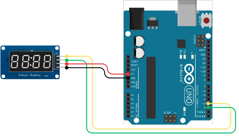
Here is the recommended wiring for the TM1637 module:
| TM1637 Pin | Connect To | Description |
|---|---|---|
| VCC | 5V | Powers the display |
| GND | GND | Common ground |
| DIO | D2 (or any digital pin) | Data line |
| CLK | D3 (or any digital pin) | Clock line |
You can use any available digital pins. The example codes in this tutorial will use D2 and D3 for simplicity.
Common Connection Mistakes
Avoid these common wiring issues to prevent display problems:
- Reversing VCC and GND. This is the most common mistake and can damage the module.
- Using very long jumper wires, which may cause unstable data communication.
- Connecting DIO and CLK to Arduino analog pins without setting them as digital pins.
- Loose jumper wires, especially on breadboards, often cause flickering digits.
- Using 3.3V power for the display. It may work, but the brightness will be very low and unstable.
Install the TM1637 Arduino Library
To make coding easier, we use the TM1637Display library. It provides ready-made functions to display numbers, adjust brightness, clear digits, and much more. Installing this library only takes a few seconds.
How to Install the Library from Arduino IDE
Follow these simple steps:
- Open the Arduino IDE.
- Go to Sketch → Include Library → Manage Libraries.
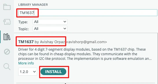
- In the search box, type “TM1637”.
- Look for TM1637Display by Avishay Orpaz.
- Click Install.
This will add all required files and examples to your IDE.
How to Verify Installation
To confirm that the library installed correctly:
- Go to File → Examples.
- Scroll down and look for TM1637Display.
- If you see example sketches, the installation was successful.
TM1637 Functions and Examples
Now we explore all the important functions of the TM1637 4-digit 7-segment display. Each function includes a small code example along with a short explanation. This will help you understand how the display behaves in real projects.
1. Displaying Numbers on TM1637
The code below can display a 1, 2, 3 or 4 digit number on the TM1637 display.
#include <TM1637Display.h>
#define CLK 3
#define DIO 2
TM1637Display display(CLK, DIO);
void setup() {
display.setBrightness(7); // Set maximum brightness
}
void loop() {
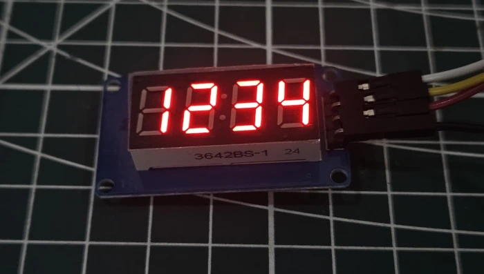
display.showNumberDec(1234); // Display a full 4-digit number
}Explanation:
showNumberDec()displays a 4-digit number.- Numbers smaller than 4 digits are padded with blank space on the left side.
- This is the simplest way to display numeric values.
Output:
The image below shows the number 1234 displayed on the TM1637 module.
2. Showing Individual Digits
The code below will display 4 digits, but individually.
#include <TM1637Display.h>

#define CLK 3
#define DIO 2

TM1637Display display(CLK, DIO);

void setup() {
  display.setBrightness(7);
  display.clear();
}

void loop() {
  display.showNumberDec(9, false, 1, 0);  // Digit 9 at position 0
  display.showNumberDec(3, false, 1, 1);  // Digit 3 at position 1
  display.showNumberDec(7, false, 1, 2);  // Digit 7 at position 2
  display.showNumberDec(2, false, 1, 3);  // Digit 2 at position 3
  delay(500);
}Explanation:
- Each digit can be updated individually by specifying its position (0–3).
- Useful for counters, timers, or animations where digits change separately.
What display.showNumberDec(9, false, 1, 0) does
This command tells the TM1637 display to show the digit 1 at position 0 (the leftmost digit).
- 9: the number to display
- false: don’t show leading zeros
- 1: display only one digit
- 0: starting position on the 4-digit display
So the result is simply:
[9] [ ] [ ] [ ]Only the first digit lights up with the number 9.
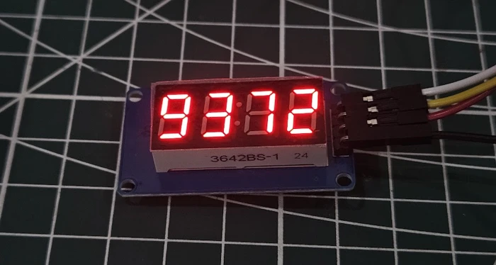
Output:
The image below shows each digit being updated individually on the TM1637 display.
3. Enabling and Blinking Middle Dots for Clock Display
In this part, we’ll control the two middle dots on the TM1637 display, the colon used in clock-style layouts. You’ll see how to turn them ON and OFF and make them blink to create a real-time clock effect, even before adding any RTC module.
#include <TM1637Display.h>

#define CLK 3
#define DIO 2

TM1637Display display(CLK, DIO);

void setup() {
  display.setBrightness(7);  // Set maximum brightness
  display.clear();
}

void loop() {
  // Display number 12:34 with middle dots ON
  display.showNumberDecEx(123, 0b11100000, true);
  delay(500);

  // Blink the dots by turning them OFF
  display.showNumberDecEx(123, 0b00000000, true);
  delay(500);
}Explanation:
showNumberDecEx(number, dots, leadingZeros)controls the middle dots.0b11100000turns both middle dots ON.0b00000000turns the dots OFF.- By alternating between ON and OFF every 500ms, you create a blinking effect, perfect for showing seconds in a clock.
truekeeps leading zeros visible for proper time formatting (like09:05).
Output:
The gif below shows the number 01:23 with blinking middle dots, simulating a real clock display.

4. Clearing the Display
#include <TM1637Display.h>

#define CLK 3
#define DIO 2

TM1637Display display(CLK, DIO);

void setup() {
  display.setBrightness(7);
}

void loop() {
  display.showNumberDec(1234);
  delay(1000);
  display.clear();  // Clears the display
  delay(1000);
}Explanation:
clear()removes all digits from the display.- Useful to reset the display before starting a new sequence.
Output:
The gif below shows the TM1637 display cleared of all digits.

Complete Arduino Projects Using TM1637 Display
After learning all the basic functions, it’s time to build complete Arduino projects. These examples show how the TM1637 display can be used in real applications. Each project includes full working code and simple explanations so you can understand how everything works.
Project 1 -> Simple Counter Display
This project shows a basic counter that increases every 200 milliseconds.
#include <TM1637Display.h>

#define CLK 3
#define DIO 2

TM1637Display display(CLK, DIO);
int counter = 0;

void setup() {
  display.setBrightness(7);
}

void loop() {
  display.showNumberDec(counter);  // Show counter value
  counter++;
  delay(200);
}Explanation:
- The
countervariable increases by 1 every 200ms. showNumberDec()updates the display with the current number.- Works for simple counters or numeric displays.
Output:
The gif below shows the TM1637 display counting numbers from 0 upwards.

Project 2 -> Stopwatch / Timer (With Blinking Colon)
This project works like a stopwatch, counting minutes and seconds up to 99:59. The colon blinks every second to mimic a real stopwatch display.
#include <TM1637Display.h>

#define CLK 3
#define DIO 2

TM1637Display display(CLK, DIO);

int seconds = 0;
int minutes = 0;
bool colonState = true;  // To toggle the colon

void setup() {
  display.setBrightness(7);
}

void loop() {
  seconds++;
  if (seconds == 60) {
    seconds = 0;
    minutes++;
  }

  int timeValue = minutes * 100 + seconds;

  // Toggle colon every second
  display.showNumberDecEx(timeValue, colonState ? 0b11100000 : 0b00000000, true);
  colonState = !colonState;

  delay(1000);
}Explanation:
colonStatevariable toggles between ON (0b11100000) and OFF (0b00000000).- This creates a blinking colon effect, like in a real stopwatch.
showNumberDecEx()displays the time in MM:SS format.- The stopwatch updates every second.
Output:
The gif below shows the stopwatch counting with a blinking colon in the middle.

3. Project -> Real Time Clock Using DS3231 + TM1637
In this project, we will display real-time clock data from the DS3231 RTC module on a TM1637 4-digit display. The colon in the middle will blink every second, giving you the look and feel of a real digital clock.
Before writing the code, let’s cover the wiring and required libraries.
Components & Libraries Required
- Arduino (UNO/Nano/Pro Mini)
- TM1637 4-digit display
- DS3231 RTC module
- Jumper wires
Installing “RTClib” Library
The RTClib library is one of the most popular libraries for DS3231. It provides simple functions to read and set the time.
Follow these steps:
- Open Arduino IDE
- Go to Sketch → Include Library → Manage Libraries
- In the search bar, type RTClib
- Install the library published by Adafruit
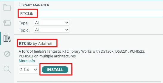
This library supports DS1307, DS3231, and other RTC modules, so it works perfectly for this tutorial.
Connection Diagram
The image below shows the wiring connection between DS3231 RTC module, TM1637 Display and Arduino.
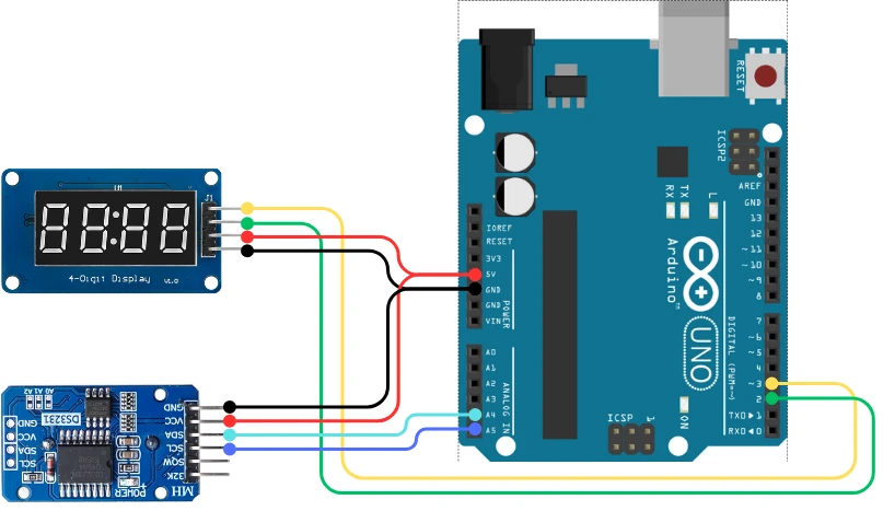
Here is the wiring in tabular form for better clarity:
| Arduino UNO | DS3231 RTC | TM1637 |
|---|---|---|
| 5V | VCC | VCC |
| GND | GND | GND |
| A4 (SDA) | SDA | – |
| A5 (SCL) | SCL | – |
| D3 | – | CLK |
| D2 | – | DIO |
Arduino Code -> Displaying Time With Blinking Colon
#include <Wire.h>
#include <TM1637Display.h>
#include "RTClib.h"

#define CLK 3
#define DIO 2

TM1637Display display(CLK, DIO);
RTC_DS3231 rtc;

bool colonState = true;  // To toggle the colon

void setup() {
  Wire.begin();
  rtc.begin();
    // Set RTC using the compile time
  rtc.adjust(DateTime(F(__DATE__), F(__TIME__)));
  display.setBrightness(7);
}

void loop() {
  DateTime now = rtc.now();

  int hour = now.hour();
  int minute = now.minute();

  int timeValue = hour * 100 + minute;

  // Toggle colon for blinking effect
  display.showNumberDecEx(timeValue, colonState ? 0b11100000 : 0b00000000, true);
  colonState = !colonState;

  delay(1000);
}Explanation
- The
colonStatevariable switches between ON and OFF every second. 0b11100000enables the colon on the TM1637 display.0b00000000turns it off.showNumberDecEx()prints the time in HHMM format while applying the colon state.- The
delay(1000)updates the display every second, creating the blinking effect.
For more details about interfacing DS3231 RTC module with Arduino, you can check my guide: Interface DS3231 RTC with Arduino.
Output
The TM1637 display will show the time in HH:MM format, with the colon blinking every second, just like a standard digital clock. This is shown in the gif below.

Project 4 -> Clock with Intermittent Temperature Display
This project shows the current time on the TM1637 display and switches to temperature every 5 seconds for 2 seconds.
#include <Wire.h>
#include <TM1637Display.h>
#include "RTClib.h"

#define CLK 3
#define DIO 2

TM1637Display display(CLK, DIO);
RTC_DS3231 rtc;

bool colonState = true;  // For blinking colon
unsigned long previousMillis = 0;

void setup() {
  Wire.begin();
  rtc.begin();
    // Set RTC using the compile time
  rtc.adjust(DateTime(F(__DATE__), F(__TIME__)));
  display.setBrightness(7);
}

void loop() {
  unsigned long currentMillis = millis();

  // Display time normally for 5 seconds
  if (currentMillis - previousMillis < 5000) {
    DateTime now = rtc.now();

    int hour = now.hour();
    int minute = now.minute();
    int timeValue = hour * 100 + minute;

    // Blink colon every second
    display.showNumberDecEx(timeValue, colonState ? 0b11100000 : 0b00000000, true);
    colonState = !colonState;
    delay(1000);
  }
  // Display temperature for 2 seconds
  else if (currentMillis - previousMillis < 7000) {
    float temp = rtc.getTemperature();
    int tempInt = (int)temp;

    // Custom segments for °C symbol on the last digit
    uint8_t segments[] = {
      display.encodeDigit(tempInt / 10),  // Tens
      display.encodeDigit(tempInt % 10),  // Units
      0,                                  // Blank
      0b01100011                           // °C symbol (custom segment)
    };
    display.setSegments(segments);
    delay(2000);
  }
  else {
    // Reset timer
    previousMillis = currentMillis;
  }
}Explanation:
- The display shows current time with a blinking colon for 5 seconds.
- Every 5 seconds, it switches to temperature display for 2 seconds.
0b01100011is a custom segment pattern to represent°Con the last digit.- Uses
millis()for non-blocking timing, so the display can alternate automatically.
Since we are build a custom segment to display °C symbol, the function display.encodeDigit is used to convert the digit to the segment data.
For more details about interfacing DS3231 RTC module with Arduino, you can check my guide: Interface DS3231 RTC with Arduino.
Output:
The gif below shows the TM1637 displaying current time normally, and then switching to temperature for 2 seconds.

These projects demonstrate how the TM1637 display can be used in real-world Arduino applications. You can now build clocks, timers, counters, and temperature displays using these examples.
Troubleshooting TM1637 Display Issues
If your TM1637 display is not working as expected, do not worry. Most problems are caused by wrong wiring, loose connections, or incorrect code settings. This section gives you a quick and simple troubleshooting guide to fix the most common issues.
Display Not Powering On
If the display stays completely blank:
- Make sure VCC is connected to 5V on the Arduino.
- Ensure GND is connected properly.
- Check the USB cable or power supply.
- Try another set of jumper wires.
- Confirm that you did not connect VCC to 3.3V by mistake, which may cause dim or no display.
Most of the time, this issue is due to a loose or wrong power connection.
Display Showing Random Segments
If random numbers or broken segments appear:
- Check the CLK and DIO pins.
- Ensure the pins in code match the actual wiring.
- Make the wires shorter to avoid noise.
- Try lowering the brightness level in the code.
- Reset the Arduino after uploading the sketch.
Random segments often mean the display is receiving unstable or incorrect data.
Incorrect Time or Digits
If the digits blink, skip, or show incorrect values:
- Verify the delay timing in the code.
- Check if the display.showNumberDec() or showNumberDecEx() is used correctly.
- For RTC projects, confirm that the DS3231 time is set correctly.
- Re-upload the code after resetting the board.
- Ensure the wires for DS3231 (SDA, SCL) are connected properly.
This issue usually happens when the data sent to the display is wrong or the RTC module time is not synchronized.
Conclusion
This tutorial covered everything you need to start using the TM1637 4-digit 7-segment display with Arduino. You learned how the module works, how to wire it, and how to use its main functions with simple code examples. You also explored complete Arduino projects, including a real-time clock using the DS3231 module.
The TM1637 display is a powerful tool for showing numbers, timers, counters, and sensor data. Because it uses only two pins, it fits perfectly in projects where I/O pins are limited. You can easily expand these examples into bigger ideas such as digital clocks, countdown timers, speedometers, and home automation displays.
With the basics now clear, you can continue experimenting, add more sensors, and build more interactive projects. The TM1637 display will help you bring your Arduino ideas to life in a simple and readable way.
Browse More Arduino Display Tutorials

ST7735 Arduino TFT Tutorial: SPI Wiring, Graphics, Text & SD Card Image Display
Arduino ILI9341 Touchscreen Tutorial: XPT2046 Wiring, Graphics, Calibration & UI
ST7920 Arduino Projects Tutorial: Real-Time Graphs, Menu System, and Full Dashboard UI using U8g2
Arduino SH1106 OLED Tutorial: I2C Wiring, Text, Bitmaps & Animations

SSD1306 Arduino OLED Tutorial: I2C Wiring, Text, Bitmaps & Animations

Arduino ST7920 Graphics Guide: How to Create Scrolling Text, Animations and Page Transitions (U8g2)
How to Interface MAX7219 7 Segment Display with Arduino | Display Text, Scrolling Message, and Time
Arduino TM1637 Project Download
Arduino TM1637 FAQs

Subscribe
Login
0 Comments
Newest
