Home ▸ Arduino ▸ Displays & Interfaces ▸
Updated On: February 6, 2026
ST7920 Graphics Tutorial with Arduino: Draw Shapes, Icons, Bitmaps and Simple UI using U8g2
This is the second guide in our ST7920 Display Series. In the first tutorial, we learned how to connect the ST7920 128×64 display with Arduino and how to print basic text using the U8g2 library. You can check the first part here:
https://controllerstech.com/st7920-arduino-tutorial-u8g2-wiring-guide/
In this tutorial, we move one step ahead. We will draw shapes, show icons, and display bitmaps on the ST7920 screen. You will learn how to use graphics mode, how to create buttons and UI boxes, and how to place images like logos or small symbols.
The goal is simple: Build clean and visually rich screens using shapes, images, and text.
Switching to Graphics Mode in ST7920 (Full-Buffer and Page-Buffer Explained)
Before we draw shapes, icons, or bitmaps, we must switch the ST7920 display to Graphics Mode. U8g2 provides two ways to handle graphics data in memory: full-buffer and page-buffer.
Both modes work well, but they behave differently in terms of RAM usage and speed. Understanding these modes will help you choose the right option for your Arduino project.
What Is Graphics Mode in ST7920
Graphics Mode allows the ST7920 display to show pixels instead of only text. In this mode, every pixel in the 128×64 screen becomes addressable. This is required for drawing shapes like lines, circles, and rectangles, and for displaying icons or bitmaps.
U8g2 handles this by maintaining a small graphics buffer in memory. You draw everything in that buffer, and then send the final image to the display. This process makes drawing simple and efficient.
Full-Buffer Mode -> When to Use It
In full-buffer mode, U8g2 keeps the entire 128×64 frame in RAM. This means the whole screen is updated in one shot.
Advantages:
- Faster drawing speed
- Smooth graphics
- Easy rendering of complex layouts
- Best for heavy graphics, UI screens, and bitmap animations
Disadvantages:
- Requires more RAM
- Not suitable for very low-memory boards
A full-buffer for a 128×64 display takes about 1 KB, which fits easily on boards like Arduino Mega or any ARM-based microcontroller.
Page-Buffer Mode -> Why It Saves RAM
Page-buffer mode breaks the screen into smaller parts, called “pages.” Only one small page is stored in RAM at a time. U8g2 draws the graphics page-by-page and sends each to the display.
Advantages:
- Much lower memory usage
- Works on small boards like Arduino Uno or Nano
- Ideal for static screens or slow updates
Disadvantages:
- Slightly slower drawing
- Complex animations may flicker
- More draw cycles required
Page-buffer mode is a good choice when your project runs on small 8-bit boards and doesn’t need fast screen refresh.
Choosing the Right Buffer for Your Project
Choosing between full-buffer and page-buffer depends on your microcontroller and the complexity of your UI.
Use Full-Buffer if:
- You are using Arduino Mega, ESP32, STM32, or similar
- You need smooth graphics or animations
- You plan to display bitmaps often
- The project has enough RAM
Use Page-Buffer if:
- You are using Arduino Uno or Nano
- Your graphics are simple
- The display updates slowly
- RAM is limited and must be saved
Both modes work well with U8g2, so you can pick the one that matches your hardware.
Drawing Shapes on ST7920 using U8g2
U8g2 makes graphics drawing simple and clean. With just a few commands, you can draw different shapes on the ST7920 screen. These shapes form the base of most UI elements like buttons, bars, and indicators.
Let’s explore the essential drawing functions you will use in almost every project.
Drawing Lines
Below is the complete Arduino sketch for drawing different types of lines on the ST7920 128×64 display using U8g2. It follows the same initialization, wiring, and display update style used in the previous tutorial.
#include <U8g2lib.h>
#include <SPI.h>
#include <Wire.h>

// Constructor
U8G2_ST7920_128X64_F_SW_SPI u8g2(U8G2_R0, /* clock=*/ 13, /* data=*/ 11, /* CS=*/ 10, /* reset=*/ 8);

void setup() {
  u8g2.begin();
}

void loop() {
  u8g2.firstPage();
  do {

    // ---- Draw various lines ----

    // Horizontal line
    u8g2.drawLine(5, 10, 120, 10);

    // Vertical line
    u8g2.drawLine(10, 5, 10, 55);

    // Diagonal (top-left to bottom-right)
    u8g2.drawLine(20, 20, 80, 50);

    // Diagonal (bottom-left to top-right)
    u8g2.drawLine(20, 50, 80, 20);

    // A "pointer" style line
    u8g2.drawLine(90, 20, 120, 35);

    // Underline text using a line
    u8g2.setFont(u8g2_font_6x10_tr);
    u8g2.drawStr(5, 60, "Line Demo");
    u8g2.drawLine(5, 62, 60, 62);

  } while (u8g2.nextPage());

  delay(1000);
}Explanation:
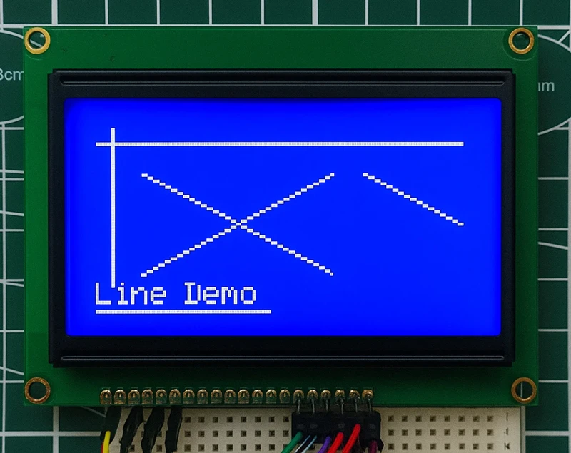
Lines are the simplest graphics you can draw on the ST7920. They help create UI elements like dividers, borders, pointers, or underlines.
U8g2 provides the line command:
u8g2.drawLine(x1, y1, x2, y2);In the example above:
- A horizontal and vertical line are drawn to show the basics.
- Two diagonal lines demonstrate angled drawing.
- A pointer-style line shows how to create indicators for menus or gauges.
- A line is also used to underline text, just like modern UI elements.
Output
The image below shows the lines output on the display.
Drawing Rectangles
Rectangles are key building blocks of simple interfaces. They are used for boxes, labels, menus, and layout elements.
U8g2 rectangle command (outline only):
u8g2.drawFrame(x, y, width, height);Below is the complete code to draw Rectangles on the display.
#include <U8g2lib.h>
#include <SPI.h>
#include <Wire.h>

U8G2_ST7920_128X64_F_SW_SPI u8g2(U8G2_R0, /* clock=*/ 13, /* data=*/ 11, /* CS=*/ 10, /* reset=*/ 8);

void setup() {
  u8g2.begin();
}

void loop() {

  u8g2.firstPage();
  do {

    // Simple rectangle box
    u8g2.drawFrame(5, 5, 50, 20);

    // Rectangle at center
    u8g2.drawFrame(40, 30, 60, 30);

    // Small UI box
    u8g2.drawFrame(100, 5, 20, 20);

    // Label under rectangle
    u8g2.setFont(u8g2_font_6x10_tr);
    u8g2.drawStr(5, 55, "Rectangle Demo");

  } while (u8g2.nextPage());

  delay(1000);
}Explanation
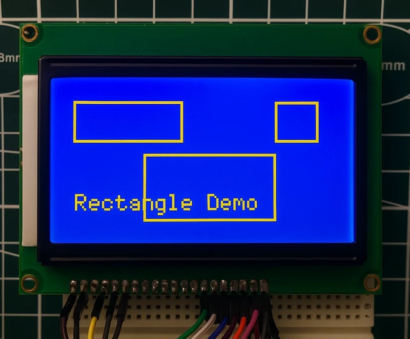
This example draws three outline rectangles of different sizes to show how they can be used for:
- UI boxes
- Menu items
- Labels and borders
drawFrame() creates thin borders without filling the inside, perfect for clean UI elements.
Output
The image below shows the rectangles on the display.
Drawing Filled Rectangles (Bars)
Filled rectangles are useful for progress bars, battery bars, or bold UI blocks. They stand out clearly on a monochrome LCD.
Command:
u8g2.drawBox(x, y, width, height);Below is the full code to Draw Filled Rectangles:
#include <U8g2lib.h>
#include <SPI.h>
#include <Wire.h>

U8G2_ST7920_128X64_F_SW_SPI u8g2(U8G2_R0, /* clock=*/ 13, /* data=*/ 11, /* CS=*/ 10, /* reset=*/ 8);

void setup() {
  u8g2.begin();
}

void loop() {

  static int barWidth = 10;

  u8g2.firstPage();
  do {

    // Filled box 1
    u8g2.drawBox(5, 10, 40, 10);

    // Filled box 2
    u8g2.drawBox(5, 30, 80, 15);

    // Animated bar (progress style)
    u8g2.drawFrame(5, 55, 100, 8);
    u8g2.drawBox(5, 55, barWidth, 8);

  } while (u8g2.nextPage());

  barWidth += 5;
  if (barWidth > 100) barWidth = 10;

  delay(400);
}Explanation
We use drawBox() to create solid filled rectangles. The last one is animated by increasing its width, just like a progress bar.
Filled shapes are essential for dashboards and indicators.
Output
The gif below shows the filled rectangles on the display.

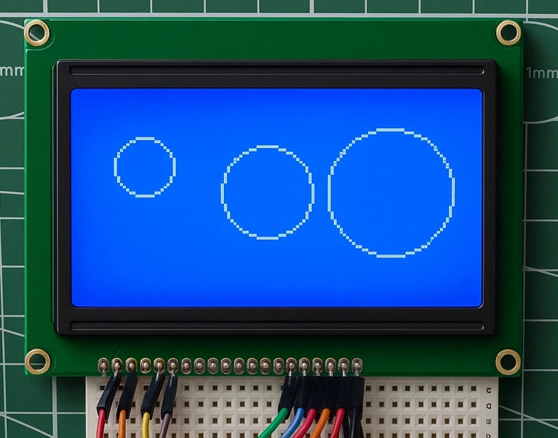
Drawing Circles
Circles are useful for indicators, round icons, radio buttons, or decorative UI elements.
Command:
u8g2.drawCircle(cx, cy, r, U8G2_DRAW_ALL);Below is the Full Code to Draw Circles:
#include <U8g2lib.h>
#include <SPI.h>
#include <Wire.h>

U8G2_ST7920_128X64_F_SW_SPI u8g2(U8G2_R0, /* clock=*/ 13, /* data=*/ 11, /* CS=*/ 10, /* reset=*/ 8);

void setup() {
  u8g2.begin();
}

void loop() {

  u8g2.firstPage();
  do {

    // Small circle
    u8g2.drawCircle(20, 20, 10, U8G2_DRAW_ALL);

    // Medium circle
    u8g2.drawCircle(60, 30, 15, U8G2_DRAW_ALL);

    // Large circle for gauge or dial
    u8g2.drawCircle(100, 30, 20, U8G2_DRAW_ALL);

  } while (u8g2.nextPage());

  delay(1000);
}Explanation
This demo draws circles of three different sizes:
- Small circle -> icons
- Medium circle -> UI symbols
- Large circle -> dials or gauges
Circles can be combined with lines to make indicators or radio buttons.
Output
The image below shows the circles output on the display.
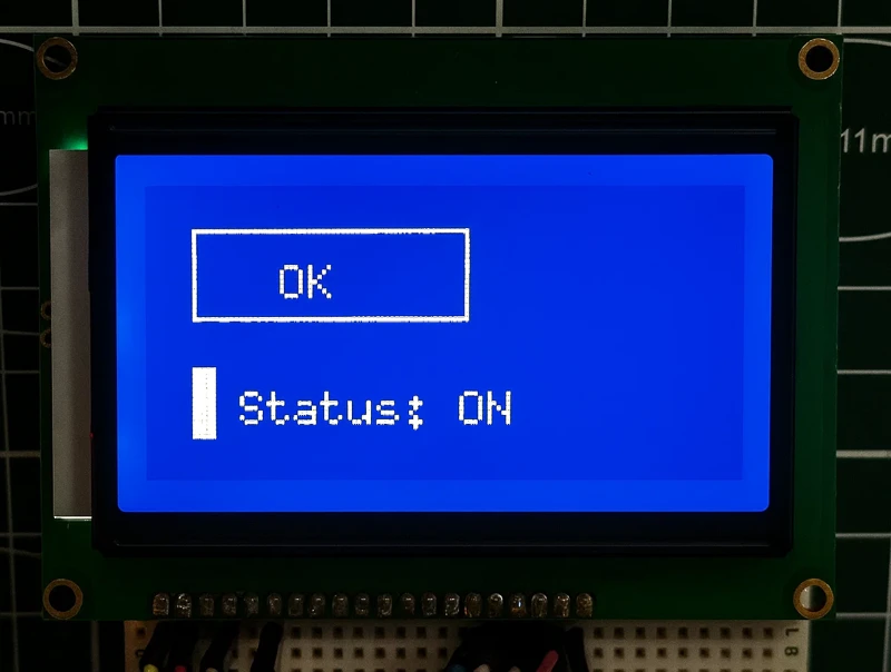
Making Simple UI Boxes (Buttons and Labels)
UI elements are made by combining shapes and text.
Two common examples:
Button
- Draw a frame
- Add text inside
Label Box
- Draw filled bar
- Place text next to it
Below is the Full Code to draw UI Boxes (Buttons & Labels)
#include <U8g2lib.h>
#include <SPI.h>
#include <Wire.h>

U8G2_ST7920_128X64_F_SW_SPI u8g2(U8G2_R0, /* clock=*/ 13, /* data=*/ 11, /* CS=*/ 10, /* reset=*/ 8);

void setup() {
  u8g2.begin();
}

void loop() {

  u8g2.firstPage();
  do {

    u8g2.setFont(u8g2_font_6x10_tr);

    // -------- BUTTON EXAMPLE --------
    u8g2.drawFrame(10, 10, 60, 20);      // button border
    u8g2.drawStr(30, 25, "OK");          // button label

    // -------- LABEL BOX EXAMPLE --------
    u8g2.drawBox(10, 40, 5, 15);         // small bar
    u8g2.drawStr(20, 52, "Status: ON");  // text next to it

  } while (u8g2.nextPage());

  delay(1000);
}Output
The image below shows the UI boxes on the display.
Why Use u8g2.firstPage() and u8g2.nextPage() ?
U8g2 uses a paged drawing system for most displays, including the ST7920. This system helps the library handle low-memory microcontrollers and also supports displays that cannot be updated in a single write.
1. U8g2 Clears and Prepares the Buffer
u8g2.firstPage();
This function resets the internal drawing buffer and prepares U8g2 for rendering the screen.
Think of it as: “Start drawing a new frame now.”
2. U8g2 Renders the Display One Page at a Time
The ST7920 needs the screen to be updated in small chunks (pages). So U8g2 does not send the whole buffer at once. Instead, it draws the screen in multiple passes.
The loop:
do {
   // Your drawing commands here
} while (u8g2.nextPage());
means:
- Draw one page
- Send that page to the display
- Move to the next page
- Draw again
- Continue until the whole screen is finished
3. You Must Put All Drawing Commands Inside the do–while Loop
Every pass inside the loop draws the same frame again, but each time U8g2 outputs a different page to the display.
So U8g2 automatically handles:
- Breaking the screen into pages
- Sending updates page-by-page
- Managing the display RAM limits
If you remove firstPage() and nextPage(), the ST7920 will not update, because U8g2 will never tell the display to paint the new frame.
Using Bitmaps and icons on ST7920
Bitmaps help you display logos, icons, and small graphics on the ST7920. Since U8g2 supports 1-bit monochrome images, it becomes very easy to show clean and sharp visuals.
Logos, splash screens, and status icons add a polished look to your project, and they work perfectly with this display.
How to Convert an Image to 1-Bit Bitmap
To use your own image, you need to convert it into a C byte array. You can easily do this using the Image2CPP online tool.
The image below shows how to create bitmap using an existing image.
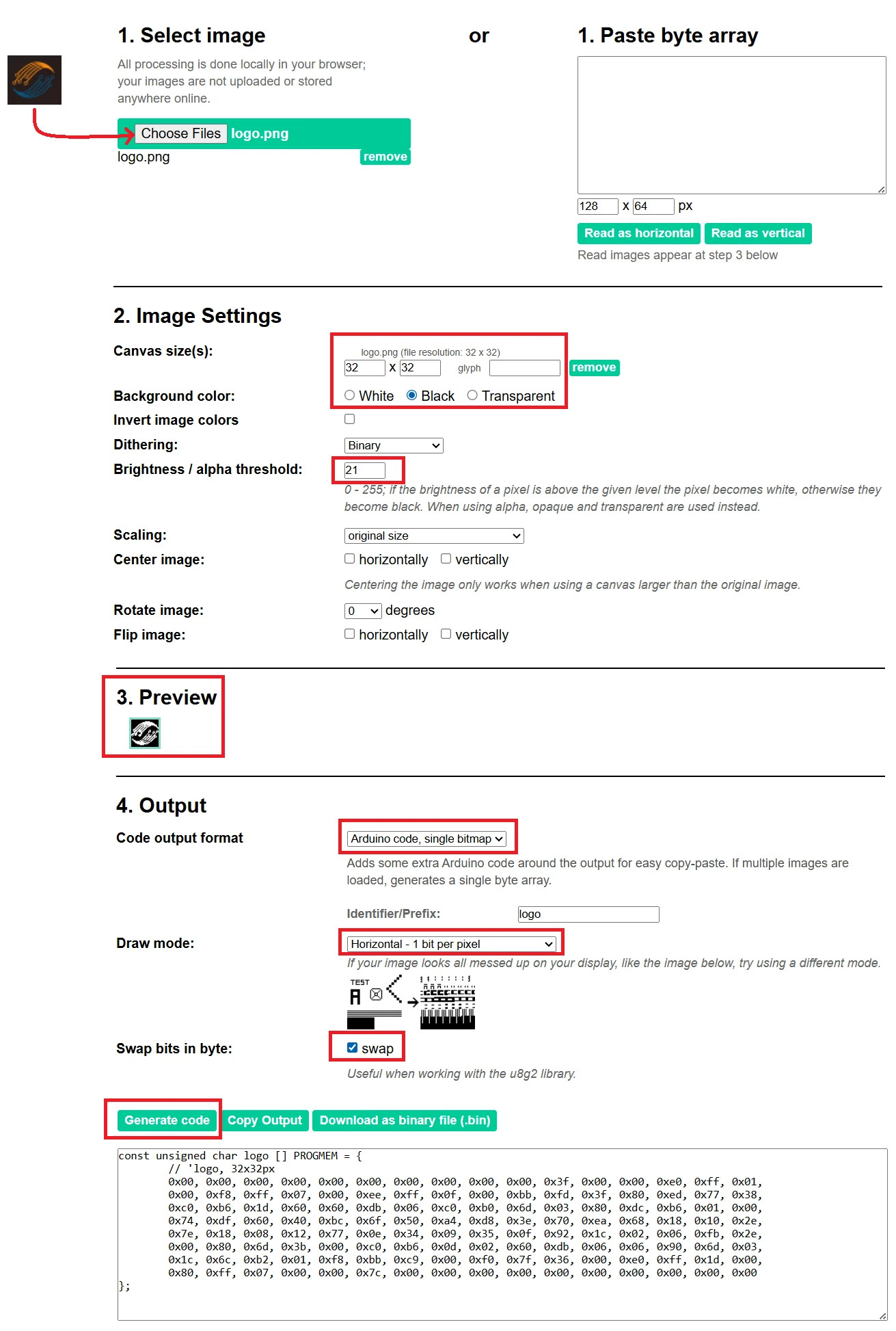
Follow these steps:
- Create a simple black-and-white image (for example, your logo).
- Upload it in Image2CPP.
- Configure the Image Settings. You can check the preview to see how the final image will look.
- Adjust the brightness/alpha threshold to generate clear image.
- Set output as Arduino Code.
- Choose Monochrome and Horizontal byte orientation.
- Enable Swap bits for the use with u8g2 library.
- Click Generate Code and copy the byte array.
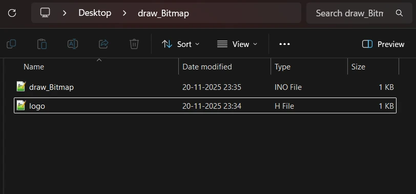
After copying the byte array, paste it in a new header file. It will keep the code clean as our image data will be in a separate file. In the image below, I have created a separate file named logo.h.
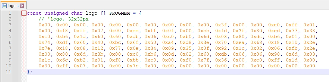
Now copy the file to the Arduino project folder, so that we can use it in the code.
Displaying a Bitmap
To show your bitmap on the ST7920, include the bitmap header file in the main file. Then use the drawXBMP() function to display the bitmap.
Here’s a simple example:
#include <U8g2lib.h>
#include <SPI.h>
#include <Wire.h>
#include "logo.h"

// Same constructor as previous ST7920 tutorials
U8G2_ST7920_128X64_F_SW_SPI u8g2(U8G2_R0, /* clock=*/ 13, /* data=*/ 11, /* CS=*/ 10, /* reset=*/ 8);

void setup() {
  u8g2.begin();

  // -------- DISPLAY SPLASH LOGO --------
  u8g2.firstPage();
  do {
    // Draw 32x32 logo centered
    u8g2.drawXBMP(48, 16, 32, 32, logo);
  } while (u8g2.nextPage());

  delay(1500);
}

void loop() {

}Explanation:
- We include logo.h, which contains the 32×32 bitmap array named logo.
drawXBMP()draws the bitmap in 1-bit format, which is ideal for ST7920.(48, 16)positions the logo in the center of the 128×64 screen.
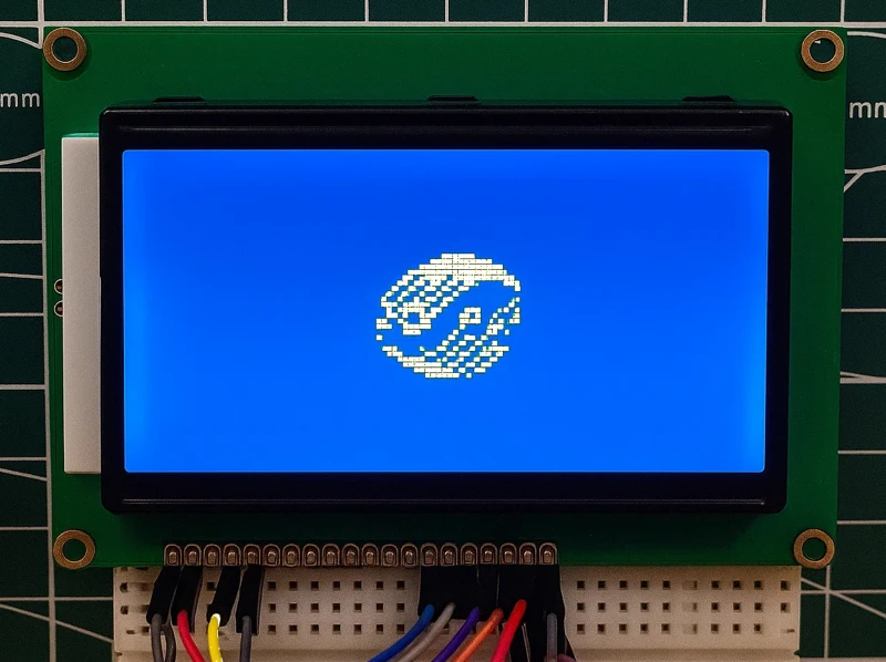
Output
The image below shows the logo bitmap on the display.
Drawing Small Icons (Battery, WiFi, Signal)
Small icons make your UI look clean and professional. On a monochrome display like the ST7920, bitmap icons give the best results because they remain sharp and consistent.
You can add icons such as:
- Battery indicators
- WiFi strength
- Signal bars
- Bluetooth symbol
- Any custom status icons
These icons are usually drawn using bitmap arrays stored in PROGMEM, and rendered with:
u8g2.drawXBMP(x, y, width, height, iconArray);Below is an example where we draw a 16×16 WiFi icon at the top right corner, and display the text “Connected” under it.
#include <U8g2lib.h>
#include <SPI.h>

// Constructor used in your previous tutorial
U8G2_ST7920_128X64_F_SW_SPI u8g2(U8G2_R0, 13, 11, 10, 8);

// ---- Corrected 16x16 WiFi Bitmap (bit-swapped) ----
const unsigned char wifi_icon [] PROGMEM = {
	// 'undefined, 16x16px
	0x00, 0x00, 0xf0, 0x01, 0xf8, 0x03, 0x1c, 0x07, 0x0e, 0x0e, 0x06, 0x0c, 0xe3, 0x18, 0xf1, 0x11,
	0x38, 0x03, 0x18, 0x03, 0x0c, 0x06, 0x0c, 0x06, 0x00, 0x00, 0x30, 0x00, 0x78, 0x00, 0x78, 0x00
};


void setup() {
  u8g2.begin();
}

void loop() {

  u8g2.firstPage();
  do {

    // ----- Draw WiFi Icon (Top-Right Corner) -----
    int iconX = 128 - 16;   // screen width - icon width
    int iconY = 0;
    u8g2.drawXBMP(iconX, iconY, 16, 16, wifi_icon);

    // ----- Draw Text "Connected" -----
    u8g2.setFont(u8g2_font_4x6_tf);
    u8g2.drawStr(iconX - 20, 26, "Connected");

  } while (u8g2.nextPage());   // required for ST7920

  delay(1000);
}Explanation
1. Drawing the Icon
u8g2.drawXBMP(iconX, iconY, 16, 16, wifi_icon);This places the 16×16 WiFi icon at the top-right corner (128 - 16).
2. Drawing the Label
u8g2.drawStr(iconX - 20, 26, "Connected");The text is placed below the icon.
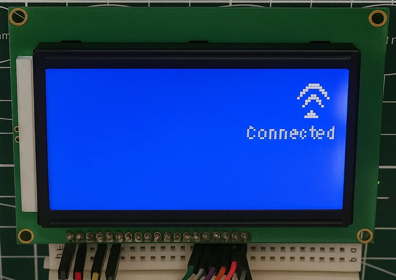
Output
The image below shows the icon and text on the display.
Mini Graphic Demos for ST7920
These small demos help you understand how to animate graphics and create useful UI elements for your ST7920-based project. Each example is simple, lightweight, and works well even on low-memory boards. You can use these elements in dashboards, menus, and device status screens.
Build a Battery Indicator
A battery icon is one of the most common UI elements in embedded displays. You can draw it easily using a simple frame + filled bar technique. The outline represents the battery body, while the fill level visually shows the remaining charge.
Battery Outline
u8g2.drawFrame(5, 5, 20, 10);  // Battery body
u8g2.drawBox(26, 7, 3, 6); // Battery tipBattery Fill Level (Dynamic)
int level = 12;  // change this for different battery levels
u8g2.drawBox(6, 6, level, 8);By increasing or decreasing level, you can animate a charging bar or show the current battery percentage. This technique works very well for sensors, handheld gadgets, and low-power devices.
Complete Example Code
This full example draws the battery outline and fills it based on a variable. You can update the level value to simulate real battery percentages.
#include <U8g2lib.h>
#include <SPI.h>

// Constructor used in your previous tutorial
U8G2_ST7920_128X64_F_SW_SPI u8g2(U8G2_R0, 13, 11, 10, 8);

int level = 0;  // Battery fill level (0–20)

void setup() {
  u8g2.begin();
}

void loop() {
  level += 2;
  if (level>=20) level=0;

  u8g2.clearBuffer();

  // Draw battery body
  u8g2.drawFrame(5, 5, 20, 10);    // Main body frame
  u8g2.drawBox(26, 7, 3, 6);       // Battery tip

  // Draw fill level
  u8g2.drawBox(6, 6, level, 8);    // Fill bar

  // Label
  u8g2.setFont(u8g2_font_6x10_tf);
  u8g2.drawStr(5, 25, "Battery");

  u8g2.sendBuffer();
  delay(1000);
}Explanation
This method is efficient and clean on monochrome displays like the ST7920.
- The drawFrame() function creates the battery outline.
- The drawBox() on the right forms the small battery tip.
- Another drawBox() inside the frame represents the current charge level.
You can animate charging by gradually increasing the level value.
Output
The gif below shows the icon and text on the display.

Create a Progress Bar
A progress bar is extremely useful for visually representing loading, updates, or any task that takes time. It is created using a simple outer frame and a filled bar that grows based on progress.
Progress Bar Structure
u8g2.drawFrame(10, 30, 100, 12);   // Outer progress bar frame
u8g2.drawBox(12, 32, progress, 8); // Filled portion of the barHere,
- Outer frame: 100×12 pixels
- Inner bar: starts from 0 and grows up to 96 pixels
Complete Animated Progress Bar Code
This example smoothly animates the loading bar from 0% to 100%, resets, and repeats.
#include <Arduino.h>
#include <U8g2lib.h>
#include <SPI.h>

// Constructor used in your previous tutorial
U8G2_ST7920_128X64_F_SW_SPI u8g2(U8G2_R0, 13, 11, 10, 8);

void setup() {
  u8g2.begin();
}

void loop() {

  // Animate progress bar from 0 to 96 pixels
  for (int p = 0; p <= 96; p++) {
    u8g2.clearBuffer();

    // Outer border of progress bar
    u8g2.drawFrame(10, 30, 100, 12);

    // Growing bar
    u8g2.drawBox(12, 32, p, 8);

    // Text label
    u8g2.setFont(u8g2_font_6x10_tf);
    u8g2.drawStr(10, 20, "Loading...");

    u8g2.sendBuffer();
    delay(20);
  }

  delay(500);  // Pause before restarting the animation
}Explanation
- The outer frame acts as the boundary of the progress bar.
- The inner bar grows horizontally as
pincreases from 0 → 96. clearBuffer()refreshes the screen on each loop so the animation looks smooth.sendBuffer()updates the ST7920 display in full-buffer mode.- The
delay(20)controls animation speed — smaller values = faster animation.
This produces a clean, modern loading animation perfect for splash screens, firmware updates, or any task progress indicator.
Output
The gif below shows the icon and text on the display.

Signal Strength Bars Animation
The Signal bars are widely used to show connection strength for WiFi, LoRa, RF, or Bluetooth. On a monochrome display like the ST7920, we can draw them using simple vertical filled rectangles (“bars”).
Each bar is slightly taller than the previous one:
u8g2.drawBox(10, 55, 4, 5);    // Bar 1 (short)
u8g2.drawBox(16, 52, 4, 8);    // Bar 2
u8g2.drawBox(22, 49, 4, 11);   // Bar 3
u8g2.drawBox(28, 46, 4, 14); // Bar 4 (tall)To animate signal strength, we simply choose how many bars are drawn based on a variable.
Complete Animated Signal Strength Code
#include <Arduino.h>
#include <U8g2lib.h>
#include <SPI.h>

// Constructor used in your previous tutorial
U8G2_ST7920_128X64_F_SW_SPI u8g2(U8G2_R0, 13, 11, 10, 8);

void setup() {
  u8g2.begin();
}

void loop() {

  // Animate signal strength from 0 to 4 bars
  for (int strength = 0; strength <= 4; strength++) {
    u8g2.clearBuffer();

    // Title text
    u8g2.setFont(u8g2_font_6x10_tf);
    u8g2.drawStr(10, 15, "Signal Strength");

    // Draw bars based on strength
    if (strength >= 1) u8g2.drawBox(10, 55, 4, 5);     // Bar 1
    if (strength >= 2) u8g2.drawBox(16, 52, 4, 8);     // Bar 2
    if (strength >= 3) u8g2.drawBox(22, 49, 4, 11);    // Bar 3
    if (strength >= 4) u8g2.drawBox(28, 46, 4, 14);    // Bar 4

    // Optional label
    u8g2.drawStr(40, 55, String(strength).c_str());

    u8g2.sendBuffer();
    delay(400);    // Slow animation so changes are visible
  }

  delay(800);      // Pause before restarting the cycle
}Explanation
- Each bar is drawn using
drawBox(x, y, width, height). - The height increases to represent stronger signal levels.
- The variable
strengthincreases from 0 → 4, enabling more bars. clearBuffer()andsendBuffer()ensure smooth animation.- This creates a clean, modern-looking signal indicator just like on phones and WiFi devices.
Output
The gif below shows the icon and text on the display.

Conclusion
In this tutorial, we explored how to build clean and modern user interfaces on the ST7920 128×64 display using the U8g2 graphics library. We covered everything from drawing basic shapes to rendering bitmap icons, creating animations, adding battery indicators, WiFi and signal-strength icons, progress bars, and small status symbols. Each example showed how easily U8g2 can handle precise graphics, smooth animations, and custom UI elements on a simple monochrome display.
By understanding these drawing techniques, you can now design richer interfaces for your embedded projects—whether you’re building IoT dashboards, sensor monitors, handheld devices, or custom controllers. With just a few lines of code, you can turn a basic display into a polished, user-friendly visual system that greatly improves the usability and professional appearance of your project.
Browse More Arduino Display Tutorials

SSD1306 Arduino OLED Tutorial: I2C Wiring, Text, Bitmaps & Animations
ST7735 Arduino TFT Tutorial: SPI Wiring, Graphics, Text & SD Card Image Display
Arduino SH1106 OLED Tutorial: I2C Wiring, Text, Bitmaps & Animations
How to Interface MAX7219 7 Segment Display with Arduino | Display Text, Scrolling Message, and Time
Arduino ST7920 Tutorial (128×64 LCD): Wiring, Setup, U8g2, and Text Display Guide
Arduino ST7920 Graphics Guide: How to Create Scrolling Text, Animations and Page Transitions (U8g2)
ST7920 Arduino Projects Tutorial: Real-Time Graphs, Menu System, and Full Dashboard UI using U8g2
Arduino ST7920 Project Download
Arduino ST7920 Graphics FAQs

Subscribe
Login
0 Comments
Newest
