Home ▸ Arduino ▸ Displays & Interfaces ▸
Updated On: February 6, 2026
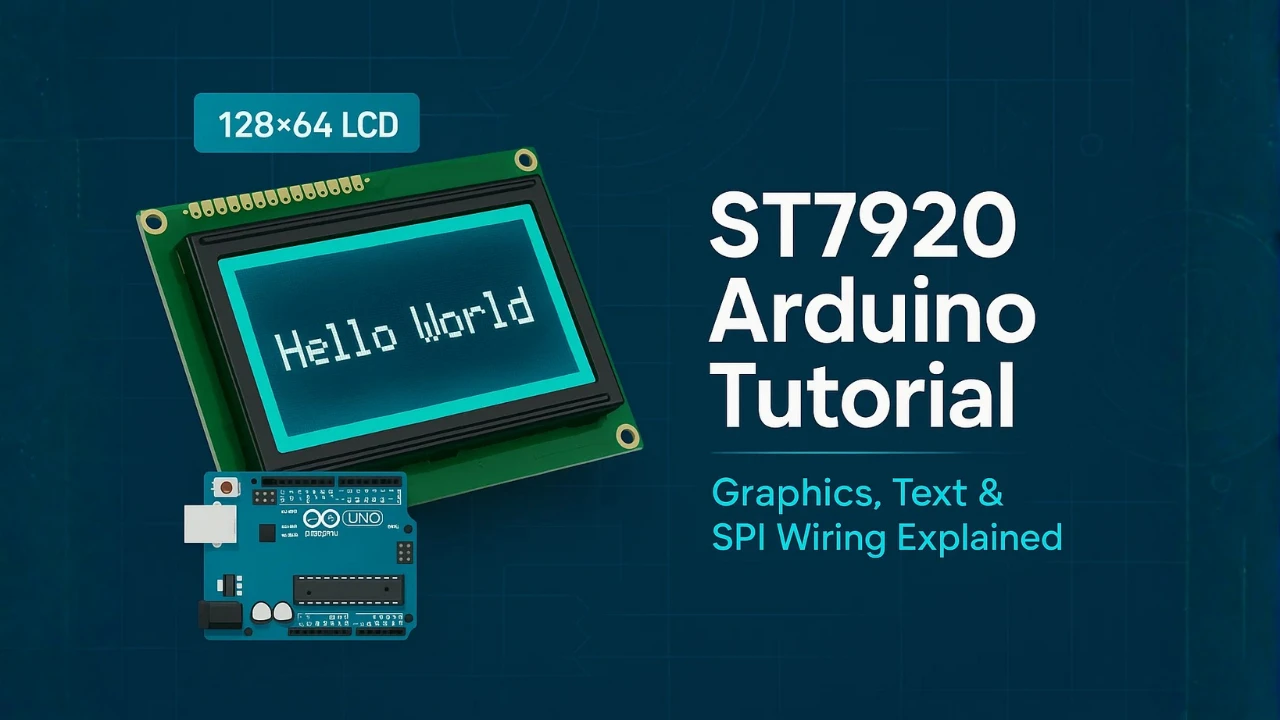
Arduino ST7920 (128×64) Display Tutorial: Introduction, Wiring, Setup and Text Display
The ST7920 128×64 graphic LCD is one of the most popular displays for Arduino projects. It is cheap, reliable and easy to control with the U8g2 graphics library. In this beginner-friendly tutorial, you will learn how to wire the ST7920 in SPI mode, install the right library, and display clear text on the screen.
We will go step-by-step, starting from the basics. You will understand the pinout, the PSB pin, the backlight pins and the power requirements. Then you will set up U8g2, run your first “Hello World” program, and explore different fonts and text styles. Finally, you will learn how to fix common issues like contrast problems, flickering, or a blank screen.
Introduction to the ST7920 128×64 Graphic LCD
The ST7920 128×64 graphic LCD is a powerful display module used in many embedded and Arduino projects. It is affordable, easy to wire, and supports both text and graphics. With the U8g2 library, beginners can control this display without dealing with low-level commands. In this section, you will learn what the ST7920 is, what it can do, and which interface mode you should use.
What Is the ST7920 128×64 Graphic LCD?
The ST7920 is a 128×64 monochrome LCD module built around the ST7920 controller chip. This controller handles all display operations such as drawing pixels, characters, and bitmaps.
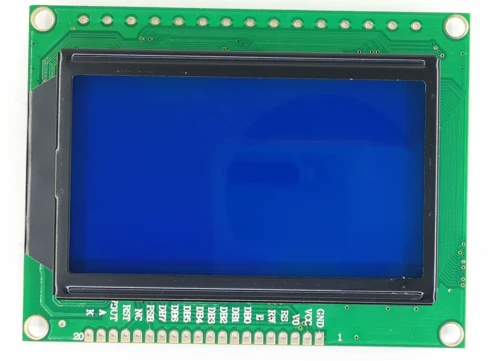
The display usually comes with a small PCB, a backlight, and a 20-pin header. You can mount it on a breadboard or use jumper wires to connect it to an Arduino. Because of its large resolution for a mono LCD, it is suitable for menus, sensor readings, icons, and simple animations.
Key Features and Display Capabilities
The ST7920 offers many useful features despite being low cost:
- 128×64 pixel resolution for clear text and graphics
- Built-in character generator, supports ASCII out of the box
- Full graphic mode, perfect for icons, bitmaps, and UI screens
- Wide viewing angle and bright LED backlight
- Operates at 5V, compatible with most Arduino boards
- Supports SPI and Parallel modes, giving flexibility
- Stable display output, no ghosting or heavy flicker
With these features, the ST7920 becomes a reliable choice for DIY projects, weather stations, clocks, data loggers, power meters, and many more Arduino builds.
Why Use the U8g2 Library for ST7920?
The ST7920 can be difficult to use if you rely on raw commands. The U8g2 library solves this problem. It handles all the complex parts and gives you simple functions for drawing text, shapes, and bitmaps.
Benefits of using U8g2:
- Easy setup for both hardware and software SPI
- Large collection of built-in fonts
- Smooth text rendering with bold, large, and compressed fonts
- Simple API for drawing lines, boxes, circles, and pixels
- Fast buffer-based drawing for flicker-free results
- Works on almost all Arduino boards
Because of these advantages, U8g2 is the most beginner-friendly and powerful library for the ST7920.
SPI Mode vs Parallel Mode (Which One to Choose?)
The ST7920 supports two interface modes:
1. SPI Mode (Recommended)
SPI mode uses fewer pins and gives stable communication. It only needs 3 data pins plus reset. This makes wiring simple and helps avoid timing issues. U8g2 also offers fast and reliable SPI constructors.
Use SPI when:
- You want fewer wires
- You use Arduino Nano, Pro Mini, or Uno
- You need more free pins for sensors or modules
2. Parallel Mode
Parallel mode uses many pins (8-bit data + control). It is faster in theory but harder to wire and not needed for most projects.
Use Parallel only if:
- You need maximum speed
- You are building a custom circuit or advanced project
ST7920 Hardware Overview and Pin Explanation
Before wiring the ST7920, it is important to understand its pinout and power requirements. The display includes multiple control pins, data pins, a special mode-select pin, and backlight pins. Learning the role of each pin will help you avoid wiring mistakes and make your setup stable.
ST7920 128×64 Pinout Table
| Pin Number | Pin Name | Function | Notes / Usage |
|---|---|---|---|
| 1 | GND | Ground | Connect to Arduino GND |
| 2 | VCC | +5V Power | Power input for the module |
| 3 | VO | Contrast Control | Connect to 10k potentiometer |
| 4 | RS | Register Select / CS | Command/Data select (Chip Select in SPI Mode) |
| 5 | RW | Read/Write / MOSI | Read or Write mode select (MOSI in SPI Mode) |
| 6 | E | Enable / SCLK | Provide Enable strobe (SCLK in SPI Mode) |
| 7 | DB0 | Data Bit 0 | Parallel mode only |
| 8 | DB1 | Data Bit 1 | Parallel mode only |
| 9 | DB2 | Data Bit 2 | Parallel mode only |
| 10 | DB3 | Data Bit 3 | Parallel mode only |
| 11 | DB4 | Data Bit 4 | Parallel mode only |
| 12 | DB5 | Data Bit 5 | Parallel mode only |
| 13 | DB6 | Data Bit 6 | Parallel mode only |
| 14 | DB7 | Data Bit 7 | Parallel mode only |
| 15 | PSB | Mode Select | LOW = SPI mode, HIGH = Parallel |
| 16 | RST | Reset | Connect to Arduino pin or 5V |
| 17 | NC | Not Connected | Ignore |
| 18 | NC | Not Connected | Ignore |
| 19 | LED+ (A) | Backlight Anode | Connect to 5V |
| 20 | LED– (K) | Backlight Cathode | Connect to GND |
Important things You MUST Remember
1. PSB pin decides the mode
- PSB = LOW -> SPI mode (best for Arduino)
- If it is HIGH, display will not respond.
2. Incorrect Contrast = Blank Screen
Without the VO pin connected, nothing will appear on the display.
A 10k potentiometer is required to set the correct contrast level.
3. Do Not Leave the RST Pin Floating
Connect RST either to:
- an Arduino pin, or
- 5V through a resistor
A floating reset pin causes unstable behavior, the display may work sometimes and fail randomly.
4. You Can Power the Backlight from a Separate 5V Source
If the backlight is drawing more current than the Arduino can handle, power it from an external 5V supply.
Just make sure the grounds are connected (common GND).
5. SPI Mode Uses Only 3 Pins
- SCLK (Clock)
- SID (Data)
- RST (Reset)
These are the only pins required for SPI communication with the ST7920.
Wiring the ST7920 in SPI Mode (Recommended)
Using the ST7920 in SPI mode is the simplest and cleanest way to connect it with an Arduino. Parallel mode requires many pins, but SPI mode needs only two data lines + CS + Reset, making it faster to wire and highly compatible with the U8g2 library.
Below is the correct wiring guide, including a pin-by-pin table in the exact order they appear on the module.
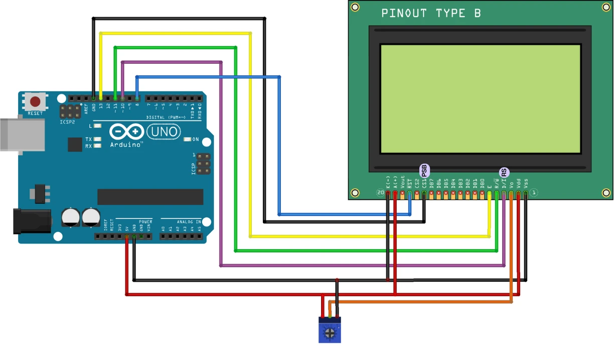
ST7920 SPI Wiring Table
(For Arduino UNO / Nano)
| ST7920 Pin No. | Pin Name | Function in SPI Mode | Arduino Pin | Important Notes |
|---|---|---|---|---|
| 1 | GND | Ground | GND | Must be common ground |
| 2 | VCC | +5V Power | 5V | Do NOT use 3.3V |
| 3 | V0 | Contrast | Middle pin of 10k pot | Wrong contrast → blank screen |
| 4 | RS | CS (Chip Select) | D10 (recommended) | Required in SPI mode |
| 5 | RW | SID (MOSI / Data) | D11 (MOSI) | Main data line |
| 6 | E | SCLK (Clock) | D13 (SCK) | SPI clock line |
| 7 | RST | Reset | D8 | Floating RST = random behavior |
| 10 | PSB | Mode Select | GND | LOW = SPI mode (MUST be grounded) |
| 11 | BLA | LED+ Backlight | 5V | Brightness depends on module |
| 12 | BLK | LED– Backlight | GND | Backlight ground |
Common Wiring Mistakes and How to Fix Them
1. PSB pin not grounded
If PSB is HIGH or floating, the display stays in parallel mode and shows nothing.
Fix: Tie PSB -> GND
2. Wrong contrast (V0)
A misadjusted contrast makes the screen appear blank.
Fix: Turn the 10k pot slowly until pixels appear.
3. RST pin left floating
Causes random resets or a blank screen.
Fix: Connect RST -> Arduino pin (D8) or pull-up to 5V.
4. Wrong U8g2 constructor
If the pin order or display type is wrong, nothing will show.
Fix: Use a U8g2 ST7920 SPI constructor with correct pin numbers.
5. Long and messy wires
SPI clock (E) is sensitive to noise.
Fix: Keep SCLK and SID wires short.
Contrast Adjustment and Potentiometer Tips
The V0 pin controls LCD contrast.
If contrast is too low, nothing will be visible.
If too high, you will see the dark blocks.
- Adjust contrast after uploading code.
- Turn the pot slowly — the visible range is small.
- A faint grid or blocks means contrast is too high.
Arduino Library Setup Using U8g2
The U8g2 library makes the ST7920 very easy to use. It includes ready-made fonts, drawing functions, and stable SPI communication. In this section, you will learn how to install the library and select the correct constructor for your wiring. After that, we will upload a simple test sketch to confirm that the display works properly.
Installing the U8g2 library is quick and simple. Follow these steps:
- Open the Arduino IDE.
- Go to Sketch → Include Library → Manage Libraries.
- In the Library Manager search bar, type “U8g2”.
- Select U8g2 by olikraus.
- Click Install.
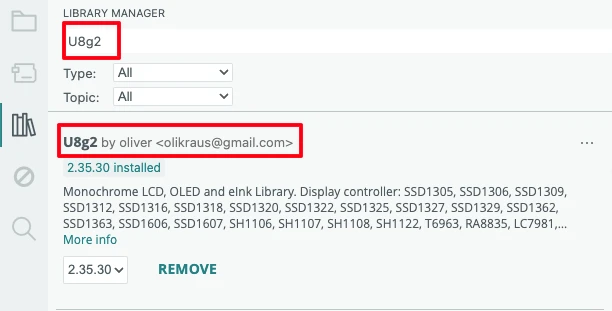
The library includes support for hundreds of displays, including the ST7920. You don’t need anything extra. After installation, restart the IDE for best results.
Choosing the Correct Constructor (Software SPI vs Hardware SPI)
Selecting the correct constructor is one of the most important steps. The constructor tells U8g2 which display you are using and which pins are connected.
1. Software SPI (Recommended for ST7920)
Software SPI lets you choose any pins, which makes wiring flexible.
This is also the most reliable method for ST7920.
Example constructor for Arduino:
U8G2_ST7920_128X64_F_SW_SPI u8g2(U8G2_R0, /* clock=*/ 13, /* data=*/ 11, /* cs=*/ 10, /* reset=*/ 8);You can change pins based on your wiring.
Use Software SPI if:
- You want custom pins
- You want stable operation
- You use Arduino Nano, Pro Mini, or Uno
2. Hardware SPI (Faster but Less Flexible)
Hardware SPI uses Arduino’s default SPI pins:
- MOSI : Pin 11
- SCK : Pin 13
Example constructor:
// Clock = 13 (E)
// Data  = 11 (RW / SID)
// CS    = 10 (RS)
// Reset = 8  (RST)

U8G2_ST7920_128X64_F_SW_SPI u8g2(U8G2_R0, 13, 11, 10, 8);- Pin 13 = Clock (E)
Sends timing pulses to the display. - Pin 11 = Data (RW / SID)
Sends pixel and character data. - Pin 10 = CS (RS)
Tells the display when it should listen. - Pin 8 = Reset (RST)
Ensures the display starts correctly every time.
Use Hardware SPI only when:
- Your wiring follows default SPI pins
- You want slightly faster performance
First Arduino Program : Displaying Text on the ST7920
In this section, you will learn how to print text on the ST7920 using the U8g2 library. We will start by initializing the display, then show a simple “Hello World”, and finally explore different fonts, centered text, and multi-line layouts.
Initialize the Display with U8g2
To begin, include the U8g2 library and create the display object.
We use Software SPI because it works with any Arduino pins and is very stable for the ST7920.
#include <U8g2lib.h>
#include <SPI.h>

// ST7920 (128x64) - Software SPI
// Clock = 13 (E), Data = 11 (RW/SID), CS = 10 (RS), Reset = 8 (RST)
U8G2_ST7920_128X64_F_SW_SPI u8g2(U8G2_R0, 13, 11, 10, 8);

void setup() {
  u8g2.begin();
}u8g2.begin() starts the display and prepares it for drawing.
If you see a blank screen here, re-check contrast and wiring.
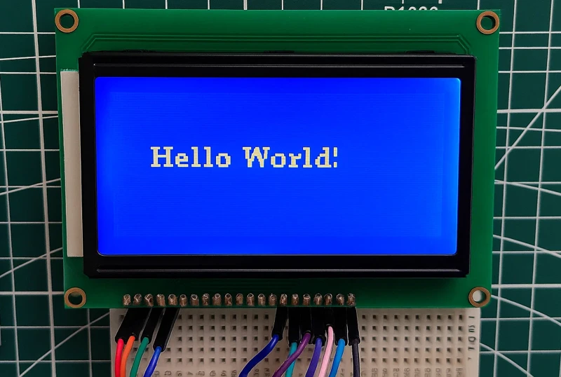
Print “Hello World!” on ST7920
The simplest way to draw text is using drawStr().
Below is a basic example that prints “Hello World!” at position (10, 30):
void loop() {
  u8g2.clearBuffer();
  u8g2.setFont(u8g2_font_ncenB08_tr);
  u8g2.drawStr(10, 30, "Hello World!");
  u8g2.sendBuffer();
}- clearBuffer()
Clears the internal graphics memory. - setFont()
Selects a readable font for the display. - drawStr(x, y, text)
Draws “Hello World!” on the screen at position (10, 30). - sendBuffer()
Sends the entire frame to the LCD, making the text appear.
This confirms your display is working. If you still see gibberish, your SPI wiring is not clean.
The image below shows the output on the display.
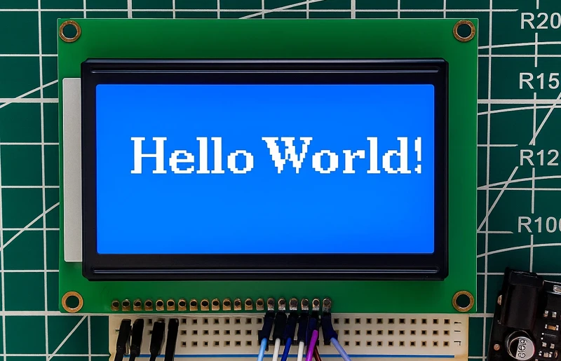
Change Fonts (Bold, Large, Fancy)
U8g2 includes hundreds of free fonts, and you can switch between them easily.
To change the appearance of your text, replace the font name:
u8g2.setFont(u8g2_font_ncenB14_tr); // Larger bold fontThe image below shows the output on the display.
Examples you can try:
u8g2_font_6x12_tr– small and cleanu8g2_font_ncenB08_tr– medium, boldu8g2_font_fub20_tr– big bold textu8g2_font_7x14B_tf– crisp bold fontu8g2_font_courB14_tr– typewriter style
You can test fonts quickly by changing only the font line.
Centered Text and Multi-Line Text Layout
You can center text by calculating its width using getUTF8Width():
const char* msg = "Centered!";
int w = u8g2.getUTF8Width(msg);
int x = (128 - w) / 2;   // center horizontally
u8g2.drawStr(x, 32, msg);The image below shows the output on the display.

Simple Multi-Line Text
Just change the Y-position for each line:
u8g2.setFont(u8g2_font_6x12_tr);

u8g2.drawStr(0, 20, "Line 1: Hello");
u8g2.drawStr(0, 35, "Line 2: Arduino");
u8g2.drawStr(0, 50, "Line 3: ST7920");The image below shows the output on the display.

ST7920 Troubleshooting Guide
The ST7920 is a reliable display, but small wiring mistakes, wrong contrast settings, or incorrect U8g2 constructors can easily make it look like the display is not working. This guide lists the most common problems beginners face and provides quick, practical fixes so you can get the display working smoothly in minutes. Whether your screen is blank, flickering, or showing mirrored text, the solutions below will help you diagnose and solve the issue fast.
Blank Screen or No Output
- Check VCC (5V) and GND connections.
- Make sure PSB is LOW → required for SPI mode.
- Verify wiring of E (CLK), RW (DATA), RS (CS) pins.
- Ensure correct U8g2 constructor is selected (SW SPI vs HW SPI).
- Adjust contrast potentiometer (usually 10k).
- Try adding a Reset pin in constructor if display doesn’t start.
Dim Backlight or Low Contrast
- Increase contrast using the onboard 10k potentiometer.
- Check LED+ and LED– wiring; some modules require a series resistor.
- Ensure the display is powered from 5V, not 3.3V.
- Avoid powering the backlight directly from Arduino 5V if it’s too weak—use external 5V.
Display Flicker or Slow Refresh
- Use full buffer mode (
_F_constructor) if performance seems slow. - Switch to Hardware SPI for faster updates.
- Avoid using
delay()inside the drawing loop. - Keep wires short and reduce noise on SPI lines.
Wrong Rotation or Mirrored Display
- Use U8g2 rotation options like:
U8G2_R0 // normal U8G2_R1 // 90° U8G2_R2 // 180° U8G2_R3 // 270° - Flip screen if mirrored:
u8g2.setFlipMode(1); - Double-check screen orientation if mounted sideways.
Conclusion
The ST7920 128×64 graphic LCD may look complex at first, but once you understand its pin functions and choose the right interface mode, it becomes a very beginner-friendly display. Using the U8g2 library greatly simplifies the entire process—whether you’re printing text, drawing shapes, making animations, or designing a complete user interface.
In this guide, you learned how to wire the display in SPI mode, set up the Arduino library, test your first “Hello World!” program, and fix the most common problems like contrast issues or flickering. With these fundamentals in place, you now have a solid foundation to experiment with more advanced features such as icons, menus, splash screens, and dynamic graphics.
The ST7920 is capable of much more than simple text. As you explore further, you’ll discover how powerful and flexible this display becomes when combined with the U8g2 library. So keep experimenting, try different fonts and layouts, and build your own fully custom graphic UI.
Browse More Arduino Display Tutorials
TM1637 Arduino Tutorial: Interface 4-Digit 7-Segment Display, Examples and Real-Time Clock Project
Arduino ILI9341 (PART 2): Build an MP3 Music Player with DFPlayer Mini
How to Interface MAX7219 7 Segment Display with Arduino | Display Text, Scrolling Message, and Time
Arduino ST7920 Display Graphics Guide: Shapes, Icons, Bitmaps, and UI Design
Arduino ILI9341 Touchscreen Tutorial: XPT2046 Wiring, Graphics, Calibration & UI
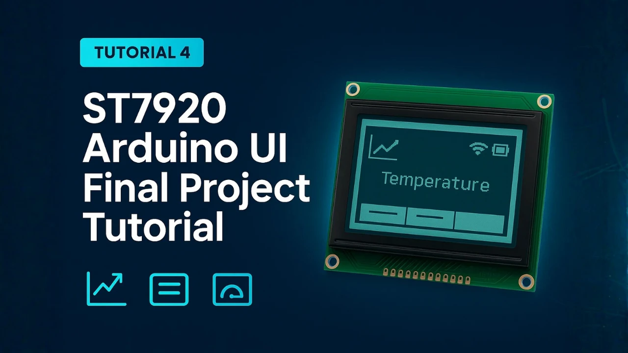
ST7920 Arduino Projects Tutorial: Real-Time Graphs, Menu System, and Full Dashboard UI using U8g2
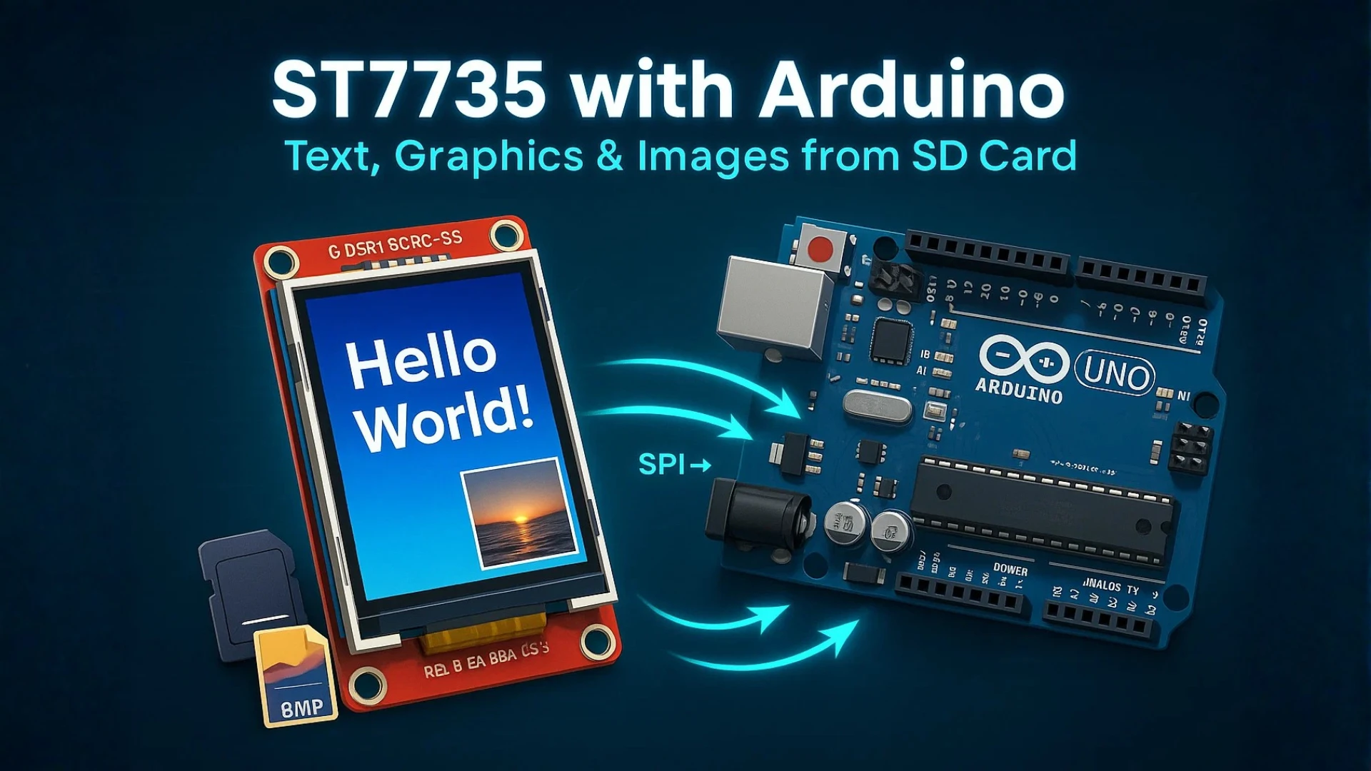
ST7735 Arduino TFT Tutorial: SPI Wiring, Graphics, Text & SD Card Image Display
Arduino ST7920 Project Download
Arduino ST7920 Display FAQs

Subscribe
Login
0 Comments
Newest
