Add Touch Interface to LVGL ESP32 Display
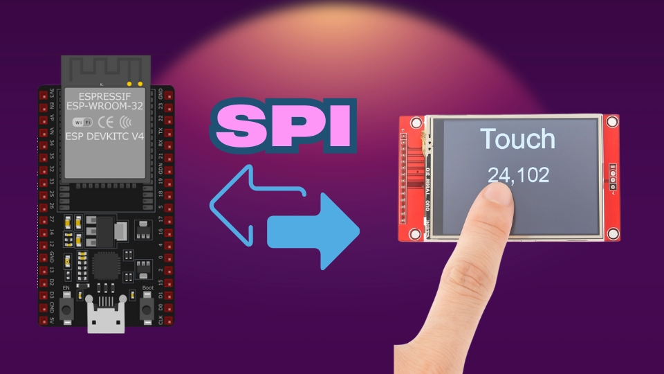
In this tutorial you will learn how to add a touch interface to an SPI LCD using ESP32. This tutorial provides a Step-by-step guide with code and circuit to create interactive touch-enabled displays.
Recommended Resources:
This is the 12th tutorial in the ESP32 series using the Espressif-IDE and 3rd in the mini series covering SPI-LCDs in ESP32. In the previous tutorials we saw how to connect the LCD to the ESP32 Dev Board and how to implement the LVGL graphic library to our project. We also covered how to create user interface using the LVGL’s squareline studio and then how to use the UI in our project.
You should take a look at the following tutorials before continuing here:
VIDEO TUTORIAL
You can check the video to see the complete explanation and working of this project.
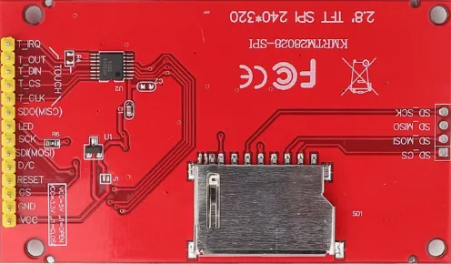
Introducing ILI9341 Display
The ILI9341 is a popular 2.4″ to 3.2″ TFT LCD display controller that supports 240×320 resolution and SPI interface. It’s often paired with the XPT2046 touch controller, enabling capacitive or resistive touch input. Together, they provide an affordable and efficient solution for graphical user interfaces in embedded systems like STM32 and ESP32.
Here are the important features of the ILI9341 Display:
- 240×320 pixel resolution with 262K color support
- SPI communication for both display (ILI9341) and touch (XPT2046)
- Integrated resistive touch support via XPT2046
- Compact size and low power consumption, ideal for embedded GUIs
WIRING DIAGRAM
Below is the image showing the connection between ESP32 and ILI9341.
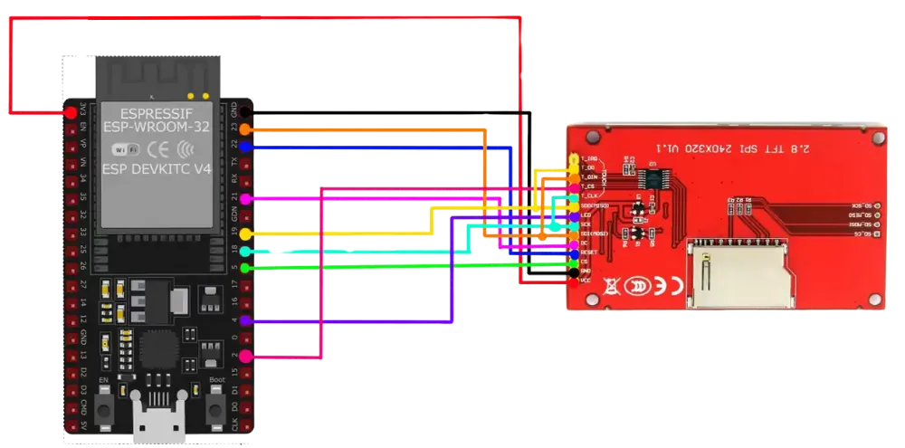
I am going to use the VSPI_HOST for the SPI. The SPI pins in the image above are defined according to it. You can check the SPI tutorial to know more about the available instances on ESP32.
The Display and Touch drivers are connected to the same SPI Pins (Mosi, Miso and SCK). Only the CS pins needs to be different.
| Pin Name | Function | Connected to |
|---|---|---|
| VCC | Power Supply (3.3V) | 3.3V |
| GND | Ground | GND |
| SDI / DI (MOSI) | SPI Data Input | GPIO23 |
| SDO / DO (MISO) | SPI Data Output | GPIO19 |
| SCK (Touch & Display) | SPI Clock | GPIO18 |
| DC / RS | Data/Command Select | GPIO21 |
| RESET | Reset Pin | GPIO22 |
| LCD_CS | Chip Select (LCD) | GPIO5 |
| Touch_CS | Chip Select (Touch – XPT2046) | GPIO2 |
| LED | Backlight Control | GPIO4 / 3.3V |
INITIAL SETUP
We will continue with the project from previous tutorial. In the previous tutorial, we have already implemented the LVGL in our project. So today we will just add the functions to include the touch interface in the previous project itself.
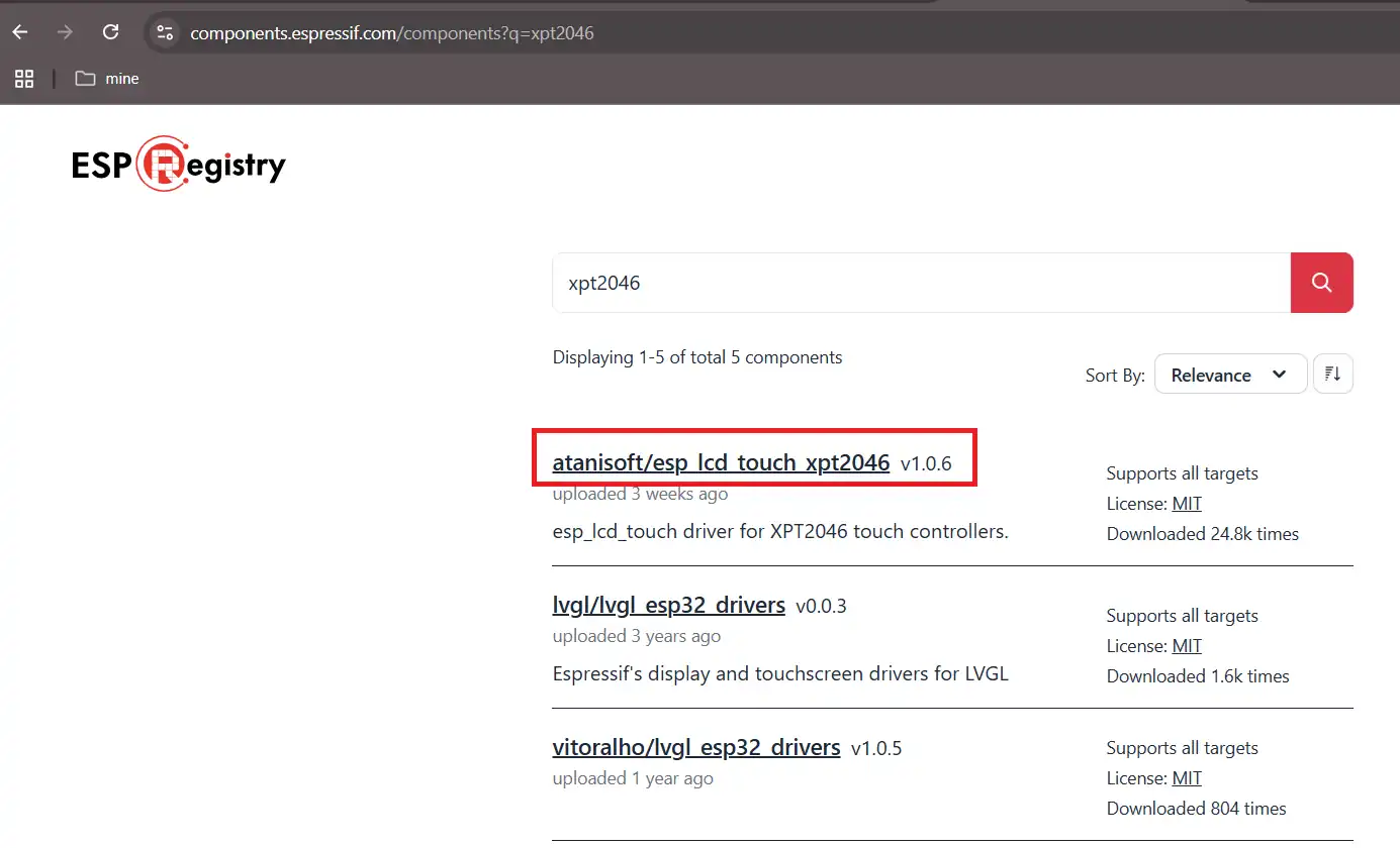
Get the Touch Library
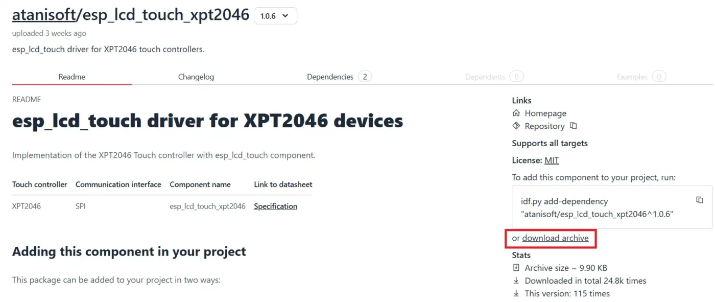
As I mentioned the ILI9341 display I am using has the touch interface XPT2046. We can download the library from the Espressif Components. Go to the https://components.espressif.com/ and search for XPT2046. You will get a lot of results, but make sure to open one with esp_lcd_**** as shown in the image below.
Download the component archive and extract it.
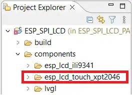
Now copy this extracted folder inside the component folder in the project.
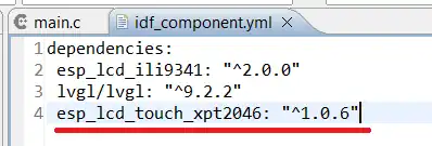
We need to link this component to our project. To do so, we will edit the file (idf_component.yml) inside the main folder and add the dependency of the XPT2046 component in this file. The LVGL version I am using is 1.0.6.
Squareline Studio
We will use the Squareline Studio to design the UI for the display. Below are the steps for creating a simple UI on the studio.
I am creating 2 screens. Both screens will have a button, when clicked, will change the screen. Below is the image showing the SCREENS.
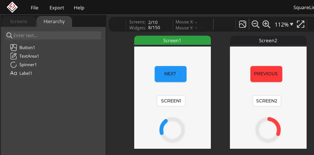
The TextArea shows the current screen. I have also added a spinner to check the animation. The button will be used to change the screen. Below is the image showing the button configuration for SCREEN1.
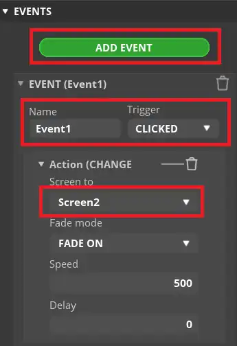
The Event will trigger when the button is clicked. It will change the screen to SCREEN2. We can also add the animation for the screen change.
Similarly the button on SCREEN2 will change the screen to SCREEN1.
Now we will export the UI files. To do so, first open the File->Project Settings and modify the UI Path and LVGL path as shown in the image below.
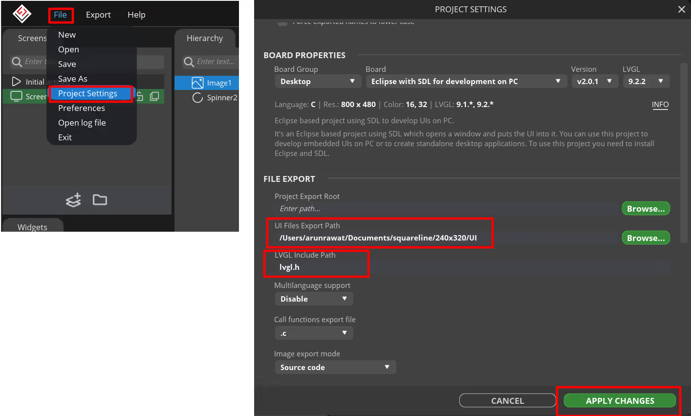
The UI Export path is where the UI files will be extracted to. I have created a folder named UI inside the project folder. This is where the UI files will be exported to. Also add lvgl.h in the LVGL include path.
Project Configuration
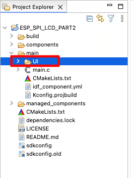
Next copy the generated UI folder inside the main folder.
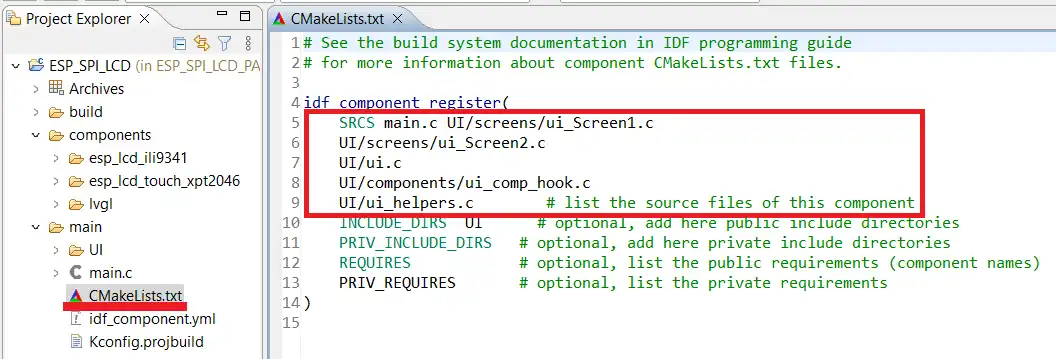
The UI files will not be recognised by the project. We need to manually include the source files in our project make file. Open the CMakeLists.txt file inside the UI folder and copy all the source files from here.
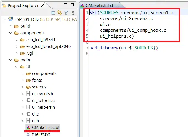
Now open the CMakeLists.txt file inside the main folder and paste the copied source files along with the main.c. Also include the folder UI in the INCLUDE_DIRS. We need to provide an additional path UI/*** in front of the source files because we are including these in the main folder.
THE CODE
We will add some more inclusions to our previously created project.
#include "esp_lcd_touch_xpt2046.h"The SPI pins used by the Touch driver are the same as the LCD driver. The only change is the use of CS pin. We need to define the CS pin along with previously defined pins.
#define PIN_NUM_TOUCH_CS 2Next We will define the LVGL Touch Callback. This function is called regularly by the LVGL to detect the touch.
static void lvgl_touch_cb(lv_indev_t * indev, lv_indev_data_t * data)
{
    uint16_t touchpad_x[1] = {0};
    uint16_t touchpad_y[1] = {0};
    uint8_t touchpad_cnt = 0;

    esp_lcd_touch_handle_t touch_pad = lv_indev_get_user_data(indev);
    esp_lcd_touch_read_data(touch_pad);
    /* Get coordinates */
    bool touchpad_pressed = esp_lcd_touch_get_coordinates(touch_pad, touchpad_x, touchpad_y, NULL, &touchpad_cnt, 1);

    if (touchpad_pressed && touchpad_cnt > 0) {
        data->point.x = touchpad_x[0];
        data->point.y = touchpad_y[0];
        data->state = LV_INDEV_STATE_PRESSED;
        printf ("Touch Pressed\n");
    } else {
        data->state = LV_INDEV_STATE_RELEASED;
    }
}Inside this callback, we will first get the touch coordinates using the function esp_lcd_touch_get_coordinates. This function stores the coordinates of the touched point inside the arrays touchpad_x and touchpad_y. This function returns true if the touch is detected, otherwise it returns false.
Once the touch is detected, we will copy the coordinates from the arrays and store them in the LVGL indev data structure. This structure will then be used by the UI to handle the touch event.
Inside the main function we will initialize the touch driver after completely initializing the LCD driver.
    esp_lcd_panel_io_handle_t tp_io_handle = NULL;
    esp_lcd_panel_io_spi_config_t tp_io_config = ESP_LCD_TOUCH_IO_SPI_XPT2046_CONFIG(PIN_NUM_TOUCH_CS);
    // Attach the TOUCH to the SPI bus
ESP_ERROR_CHECK(esp_lcd_new_panel_io_spi((esp_lcd_spi_bus_handle_t)LCD_HOST, &tp_io_config, &tp_io_handle));The function ESP_LCD_TOUCH_IO_SPI_XPT2046_CONFIG will configure the CS pin for the touch. The SPI pins are the same as the LCD, so we do not need to configure them again.
We will then add the touch panel to the SPI by calling the function esp_lcd_new_panel_io_spi.
Next we will configure the XPT2046 driver.
    esp_lcd_touch_config_t tp_cfg = {
        .x_max = LCD_H_RES,
        .y_max = LCD_V_RES,
        .rst_gpio_num = -1,
        .int_gpio_num = -1,
        .flags = {
            .swap_xy = 0,
            .mirror_x = 0,
            .mirror_y = 1,
        },
    };
    esp_lcd_touch_handle_t tp = NULL;

    printf("Initialize touch controller XPT2046\n");
ESP_ERROR_CHECK(esp_lcd_touch_new_spi_xpt2046(tp_io_handle, &tp_cfg, &tp));The Touchpad resolution is configured the same as LCD. We will not use the interrupt pin and reset pin, therefore they are set to -1.
You can test the touchpad to see if some swap or mirror along any axis is needed. Initially when I tested the touch, I found out that the coordinates are mirrored along the Y axis. That is why the mirror_y is set to 1. You can see this in the video at the end of this post.
Next we will initialize the LVGL indev driver.
    static lv_indev_t *indev;
    indev = lv_indev_create();  // Input device driver (Touch)
    lv_indev_set_type(indev, LV_INDEV_TYPE_POINTER);
    lv_indev_set_display(indev, display);
    lv_indev_set_user_data(indev, tp);
lv_indev_set_read_cb(indev, lvgl_touch_cb);- Here first create the LVGL indev driver.
- Next set the indev device type as the Pointer.
- Then link the indev driver with the display driver.
- Next connect the indev driver to the Touchpad we initialized above.
- Finally set the callback for the touch.
The rest of the code will remain the same as what we wrote in the previous project.
RESULT
Below is the gif showing the project working.

You can see the touch is working fine. The buttons are also responding, and we can see the screens changing when the button is clicked.
PROJECT DOWNLOAD

