Home ▸ STM32 Tutorials ▸
Published: March 16, 2019
Last Updated: January 16, 2026
Last Updated: January 16, 2026
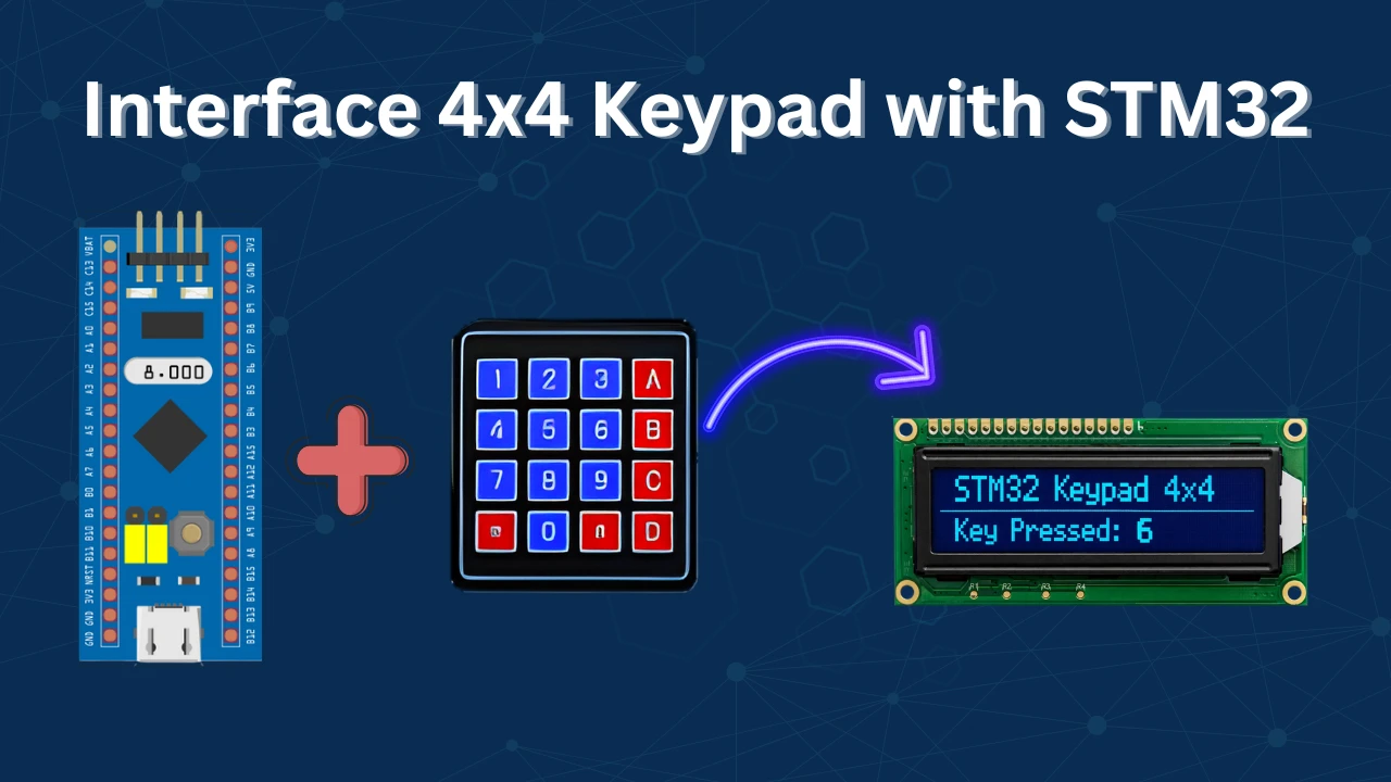
How to Use 4×4 keypad with STM32
A 4×4 keypad is a very common input device used in embedded systems for applications such as password entry, menu navigation, access control, and user input interfaces. When working with STM32 microcontrollers, interfacing a keypad is a simple yet important exercise that helps us understand GPIO configuration, scanning techniques, and basic input handling.
In this tutorial, we will learn how to interface a 4×4 matrix keypad with an STM32 microcontroller step by step. We will start by understanding how the keypad works internally using rows and columns. Then, we will configure the required GPIO pins using STM32CubeMX and write the necessary HAL code to scan the keypad and detect key presses. By the end of this tutorial, you will be able to read keypad inputs reliably and use them in your own STM32 projects for various user-interaction based applications.
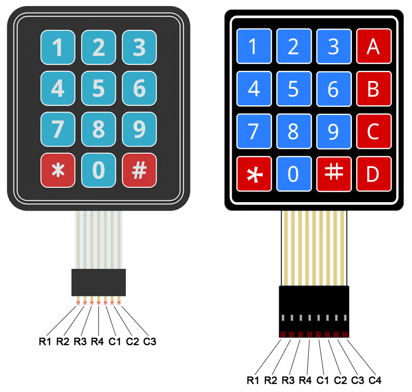
It does not matter which keypad you use or how many KEYs it have. We will use a method which can be used universally with any type of keypad or microcontroller out there.
Understanding the Working of a Matrix Keypad
Let’s start this discussion on How to actually interface a keypad with any microcontroller. The concept is pretty simple. The Keys in the keypad are divided into ROWs and COLUMNs and we are going to use these to find out which key has been pressed.
Below is the image showing how the keys are connected in the form of Rows and Columns.
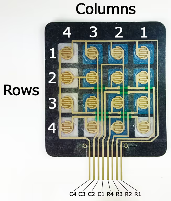
As shown in the picture above, the Keypad have 16 keys and they are divided in 4 ROWs and 4 COLUMNs. All the keys in a single ROW are interconnected and all keys in a single COL are interconnected.
We will connect the ROWs to output pins and the COLs to the input pins.
To identify the key pressed, we will pull one of the ROWs to LOW and other ROWs to HIGH. Whenever a key is pressed, the connection between ROW and COL gets completed and the COL pin will read 0. Now both, the ROW and COL will be 0 and we will know which pin has been pressed.
For example:
Let’s say I pressed the key 5. To identify this, we need to pull the R2 to LOW and than check for the Columns. Whenever the ‘5’ is pressed, the C2 will be pulled LOW as the connection between R2 and C2 will be completed. And for this combination of R2 and C2 being LOW, will be assigned value ‘5’.
STM32 CubeMX Configuration
Pin Configuration
Below is the image showing the pin configuration in the cubeMX.
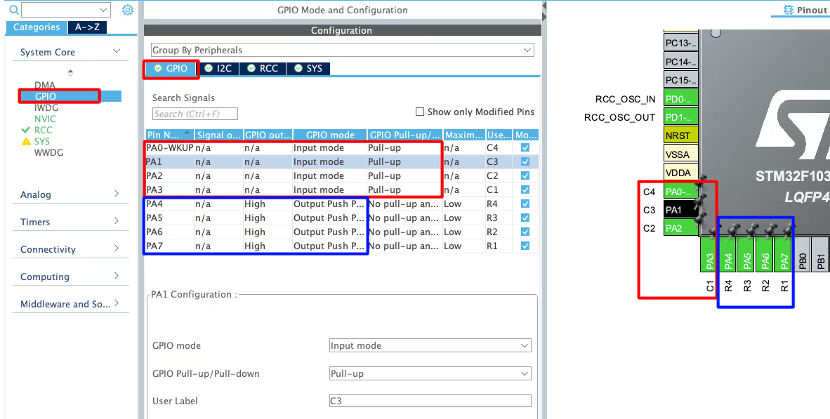
As you can see in the image above, I have configured 4 pins PA0 – PA3 as input pins and renamed them C1 – C4. These are the pins where we will connect the column pins. These pins are pulled Up by default.
The pins PA4 – PA7 are configured as the output pins and they are renamed as R1 – R4. These are the pins where we will connect the Row pins. These pins are pulled LOW by default.
I2C Configuration
I am using the LCD1602 to display the current Time and Date. The LCD is connected using the PCF8574 I2C extender. Below is the image showing the I2C configuration.
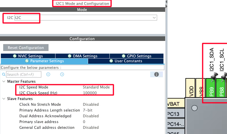
I am using the I2C1 to connect the LCD. The I2C is configured in the standard mode with the clock speed set to 100KHz. The pins PB8 and PB9 are configured as the SCL and SDA pins.
We have already covered how to interface the LCD via I2C with STM32. You can check out the tutorial for more details.
Wiring the Keypad to STM32
The image below shows the connection between the keypad and the STM32.
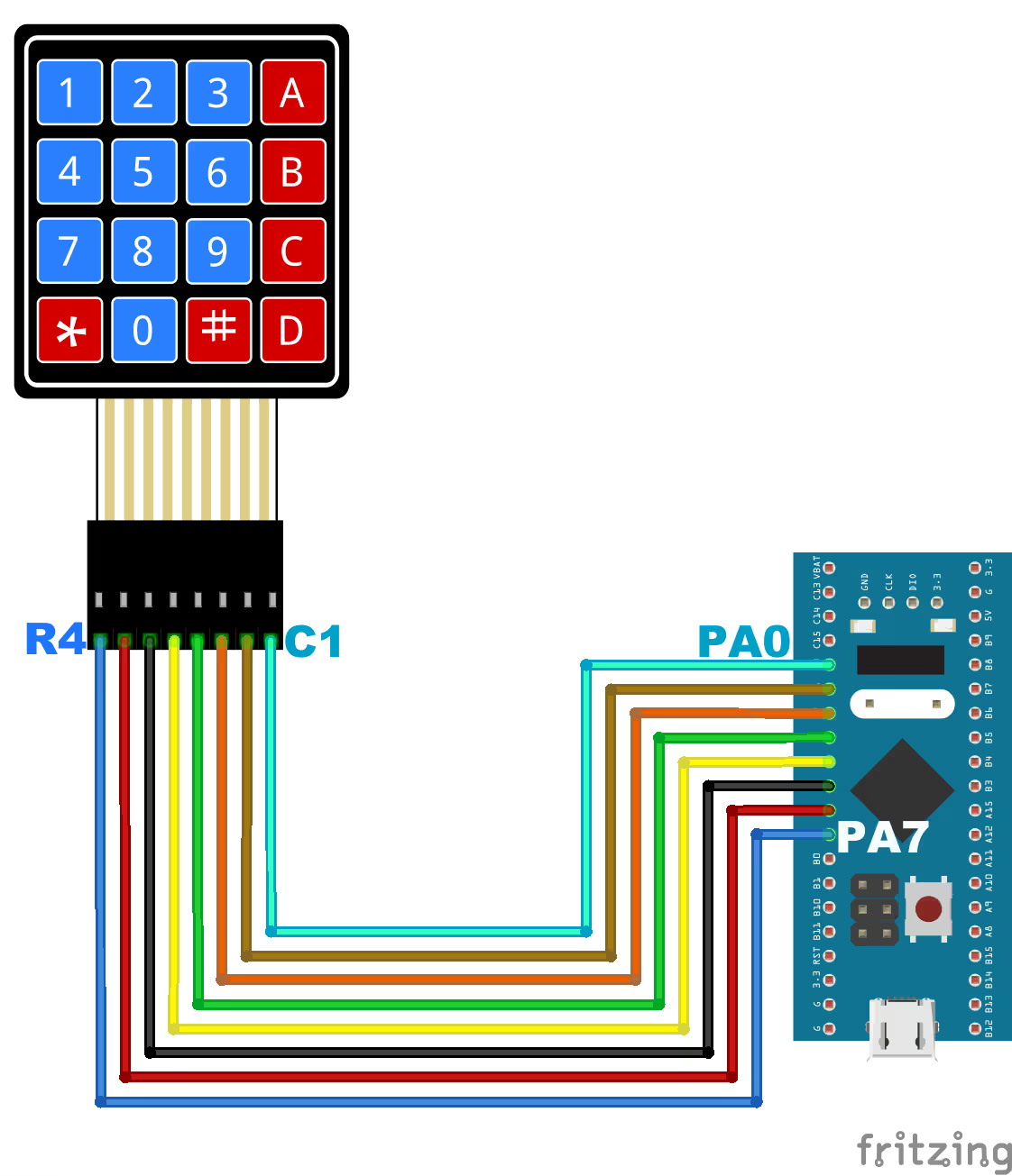
As you can see in the image above:
- The pins PA7 – PA4 are connected to the Row pins R4 – R1 respectively.
- The pins PA3 – PA0 are connected to the Column pins C4 – C1 respectively.
STM32 HAL Code to Interface 4×4 Keypad
We will define a separate function to read the data in the blocking mode.
char read_keypad (void)
{
	/* Pull ROW 1 to LOW and all other ROWs to HIGH */
	HAL_GPIO_WritePin (R1_GPIO_Port, R1_Pin, GPIO_PIN_RESET);  //Pull the R1 low
	HAL_GPIO_WritePin (R2_GPIO_Port, R2_Pin, GPIO_PIN_SET);  // Pull the R2 High
	HAL_GPIO_WritePin (R3_GPIO_Port, R3_Pin, GPIO_PIN_SET);  // Pull the R3 High
	HAL_GPIO_WritePin (R4_GPIO_Port, R4_Pin, GPIO_PIN_SET);  // Pull the R4 High

	if (!(HAL_GPIO_ReadPin (C1_GPIO_Port, C1_Pin)))   // if the Col 1 is low
	{
		while (!(HAL_GPIO_ReadPin (C1_GPIO_Port, C1_Pin)));   // wait till the button is pressed
		return '1';
	}

	if (!(HAL_GPIO_ReadPin (C2_GPIO_Port, C2_Pin)))   // if the Col 2 is low
	{
		while (!(HAL_GPIO_ReadPin (C2_GPIO_Port, C2_Pin)));   // wait till the button is pressed
		return '2';
	}

	if (!(HAL_GPIO_ReadPin (C3_GPIO_Port, C3_Pin)))   // if the Col 3 is low
	{
		while (!(HAL_GPIO_ReadPin (C3_GPIO_Port, C3_Pin)));   // wait till the button is pressed
		return '3';
	}

	if (!(HAL_GPIO_ReadPin (C4_GPIO_Port, C4_Pin)))   // if the Col 4 is low
	{
		while (!(HAL_GPIO_ReadPin (C4_GPIO_Port, C4_Pin)));   // wait till the button is pressed
		return 'A';
	}

    ..........
    ..........
}The function read_keypad will read the keypad in the blocking mode and return the character(Key) detected.
- Here first we will pull the ROW1 to LOW and all other ROWs to HIGH.
- Then we keep monitoring for the columns. If COL1 is low, that means the key pressed is ‘1’ or else if the COL2 is low, that means the key pressed is ‘2’ and so on.
- Similarly, we do the same for other ROWs as well, until all ROWs are covered.
The main function
int main()
{
  ....
  lcd_init();
  lcd_clear();
  lcd_put_cur(0, 0);
  lcd_send_string("KEY: ");
  while (1)
  {
	  char key = read_keypad();
	  if (key!=0x01)
	  {
		  lcd_send_data(key);
	  }
  }
} Inside the main function, we will initialise the LCD and send a fixed string (KEY: ) to it.
Then inside the while loop, read the key pressed on the keypad. If the key is pressed, we will print the key character on the display.
Result on the LCD Display
Below are the images showing the output on the LCD.
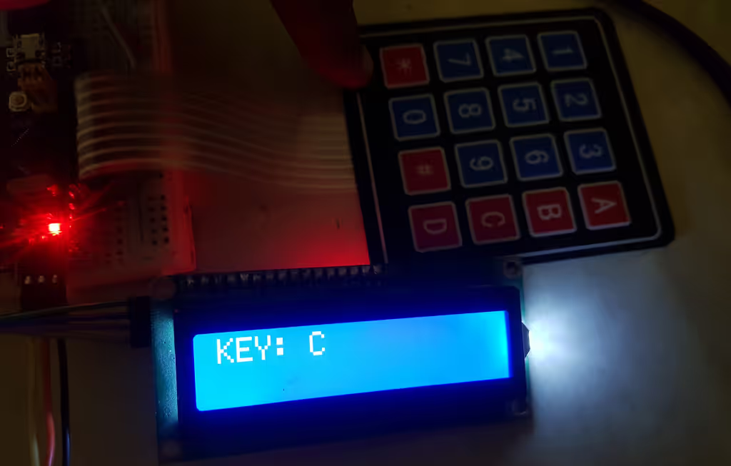
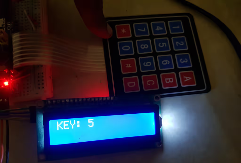
When the respective key is pressed, it is displayed on the LCD. The first image shows the key C on the LCD, while the second image shows the key 5.
VIDEO TUTORIAL
STM32 4×4 Keypad Interface – Video Tutorial
In this tutorial, we show how to interface a 4×4 matrix keypad with an STM32 microcontroller using GPIO pins and STM32CubeIDE. We will go through the keypad wiring, GPIO configuration in CubeMX, and the keypad scanning logic used to detect key presses using rows and columns. A step-by-step video walkthrough is included so you can clearly see how the scanning works and how the code identifies the pressed key.
Watch the Keypad Video TutorialConclusion
In this tutorial, we learned how to interface a 4×4 matrix keypad with an STM32 microcontroller step by step. We covered the internal working of the keypad using rows and columns, configured the GPIO pins using STM32CubeMX, and implemented the keypad scanning logic in code to detect key presses accurately. By pulling one row LOW at a time and reading the column inputs, we were able to identify exactly which key was pressed.
Interfacing a keypad is a very useful skill when building embedded applications that require user input, such as password systems, menu navigation, calculators, and access control projects. The same scanning technique explained in this tutorial can be easily extended to other matrix keypads or input devices. Once you understand this concept, you can further enhance your project by adding features like debouncing, interrupts, or combining the keypad with displays and other peripherals.
Checkout More STM32 Tutorials

STM32 W5500 Ethernet Tutorial (PART 3): TCP Server with FreeRTOS
STM32 USB CDC Tutorial: Device and Host Example Using HAL + CubeMX

Modbus #1. STM32 Master Reads Holding and Input Registers

FreeRTOS TUTORIAL #4 -> Using Counting Semaphore

WS2812 LEDs using SPI
STM32 ADC Using LL Drivers (Part 1): Single Channel Blocking and Interrupt Mode


I appreciate you for this tutorial. would you please provide another tutorial for interrupt method as you said above.
thanks in advance
hi would you like to please share the wiring diagram
how to connect both keypad and LCD with STM
no debouncing ??
hi
4*4 keypad download link do not work
It’s working fine.. maybe some issues earlier