
Home ▸ STM32 Tutorials ▸
Published: June 2, 2018
Last Updated: January 14, 2026
Last Updated: January 14, 2026
How to Interface 28BYJ‑48 Stepper Motor with STM32 Using ULN2003 Driver
In this tutorial, you’ll learn how to interface the popular 28BYJ‑48 stepper motor using the ULN2003 driver and STM32 HAL library via STM32CubeMX.
We’ll cover the complete setup, including wiring, timer configuration, and code implementation for wave, full, and half-step driving modes. Whether you’re building a robotic arm or a precision control system, this guide will help you get started with accurate motor control using STM32.
By the end, you’ll be able to drive stepper motors with accurate motion control using STM32 and the HAL library.
You should also take a look at the following guides:
- Generate Microseconds Delay using Timer
- How to Control Servo Motor using PWM
- How to Interface BLDC Motor with STM32
- How to use a Continuous Rotation Servo
Introducing the 28BYJ-48 Stepper Motor
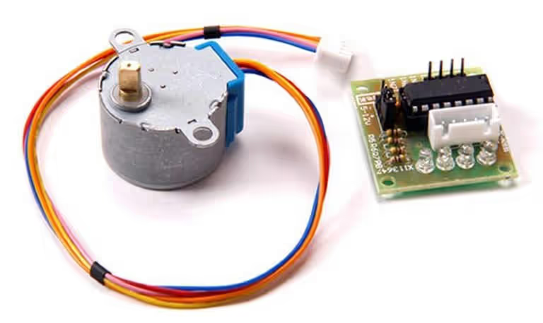
The 28BYJ‑48 is a popular and cost-effective unipolar stepper motor, commonly used in DIY electronics, automation, and robotics projects. It is often bundled with the ULN2003 driver board, which makes interfacing with microcontrollers like STM32 simple and efficient. The motor operates through step sequences that allow precise control over rotation angle and speed.
The ULN2003 driver module contains seven Darlington transistor arrays, which handle the higher current required to drive the motor coils. This makes it ideal for controlling the 28BYJ‑48 directly from GPIO pins using logic-level signals.
Key Features of 28BYJ‑48:
- 5V Operating Voltage: Runs directly from 5V, making it suitable for most microcontroller platforms.
- Step Angle of 5.625°/64 (Gear Reduction): With internal gear reduction, it offers a very fine resolution of rotation — ideal for precise movements.
- Low Power Consumption: Consumes minimal current (~240mA per phase), suitable for battery-powered or embedded systems.
- Easy Interfacing with ULN2003 Driver: The driver board simplifies control with onboard input indicators and standard connector pins.
This combination is perfect for beginner projects like robotic arms, camera sliders, and automation systems where accurate step control is required.
Why should you use the 28BYJ-48 ?
The 28BYJ‑48 stepper motor is an excellent choice for hobbyists, students, and embedded developers who need precise motion control at a low cost. It is one of the most affordable and widely available stepper motors, making it ideal for small-scale automation and learning projects.
Top Reasons to Use the 28BYJ‑48:
- Precise Control:
With a step angle of 5.625° and an internal gear ratio of 1:64, it offers high positional accuracy — perfect for tasks requiring controlled rotation. - Low Voltage & Current Requirements:
Operates at just 5V with low current (~240 mA per phase), so it can be powered directly from most development boards or USB sources. - Easy to Interface with ULN2003 Driver:
The included ULN2003 driver module allows quick connection to microcontrollers like STM32, Arduino, or ESP32 — no need for complex circuits. - Ideal for Learning and Prototyping:
Its slow speed and smooth stepping behavior make it great for learning stepper control algorithms and testing motor-driven systems. - Widely Supported:
Supported in many online tutorials (including STM32 HAL/CubeMX), example codes, and libraries, making development easier and faster.
In short, the 28BYJ‑48 is perfect for low-cost, low-speed applications where accurate control and ease of use are more important than torque or speed.
How to Drive the 28BYJ-48 Stepper Motor
Stepper motor 28BYJ-48 generally comes along with an IC ULN2003. This IC is used to drive motor because microcontroller pins are unable to provide sufficient current to drive these motors. There are three different types of stepping modes used for stepper motors:-
- Wave Drive
- Full Drive
- Half Drive
Wave Drive
In Wave Drive mode, also known as single-coil excitation, only one coil (electromagnet) of the stepper motor is energized at a time. This means the motor steps from one position to the next by activating one phase after another in a specific sequence.
Unlike other driving methods that energize multiple coils simultaneously, wave drive minimises power consumption by using just one coil at any moment. However, it also produces less torque, making it less suitable for high-load applications.
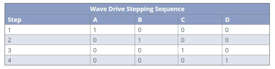
Although only one coil is active at a time, the number of steps per revolution remains the same as in full-step drive. For the 28BYJ‑48 stepper motor, a full 360° rotation requires:
- 2048 steps per revolution
- Since each full cycle of 4 coil activations (A → B → C → D) equals one step, it takes:
2048 / 4 = 512 sequences to complete one full revolution
So, in wave drive mode, the motor goes through 512 such sequences (each consisting of 4 individual coil steps) to rotate once fully.
Full Drive
In Full Step Drive mode, also known as dual-coil excitation, two stator coils are energized at the same time during each step of the motor’s rotation. This means that at every step, two electromagnets pull the rotor, providing stronger magnetic force compared to Wave Drive.
Because two coils are active simultaneously, the torque output is significantly higher, making Full Drive ideal for applications where the motor needs to handle more load or overcome resistance.
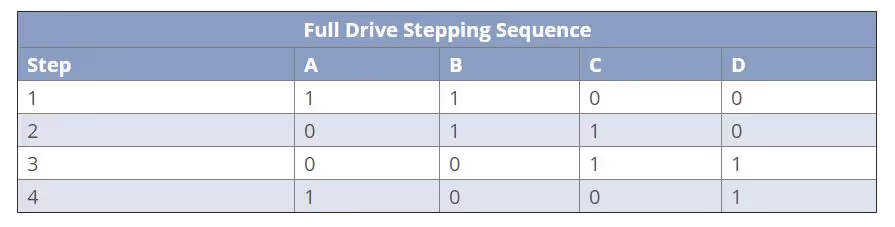
Just like in Wave Drive, the number of steps to complete one full revolution remains the same. For the 28BYJ‑48 stepper motor, it still takes:
- 2048 steps per revolution
- Each sequence involves 4 coil states (AB → BC → CD → DA), so:
2048 / 4 = 512 sequences per full rotation
The rotor moves the same distance per step as in Wave Drive, but with more force and better holding torque.
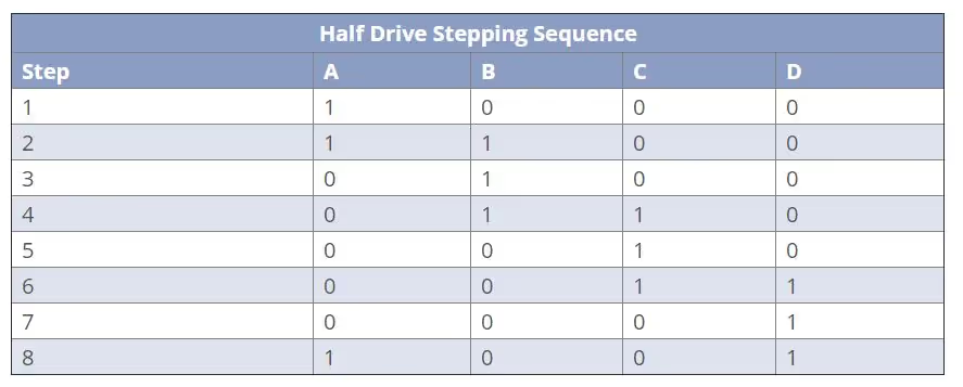
Half Drive
Half Step Drive, also known as half-stepping, is a combination of both Wave Drive and Full Step Drive modes. In this method, the motor is driven by alternating between energizing one coil and two coils. This results in smaller step angles and smoother motor movement.
By activating the coils in this alternating pattern, the motor effectively doubles its angular resolution. Instead of stepping once per coil change, it now steps halfway between the previous positions. This improves the precision and smoothness of the rotation, making it ideal for applications requiring finer control.
However, because the motor is not always running with both coils energized, the torque is lower than Full Drive, but higher than Wave Drive — making it a good balance between torque and resolution.
For the 28BYJ‑48 stepper motor, Half Step Drive mode increases the number of steps to:
- 4096 steps per revolution
- Each full cycle now includes 8 coil states, so:
4096 / 8 = 512 sequences per full revolution
Thus, the number of drive sequences remains the same, but each sequence consists of 8 half steps instead of 4 full steps.
Wiring Diagram: Connect Motor with STM232
Below is the image showing the connection between the stepper motor 28BYJ-48, ULN2003 and STM32F103.
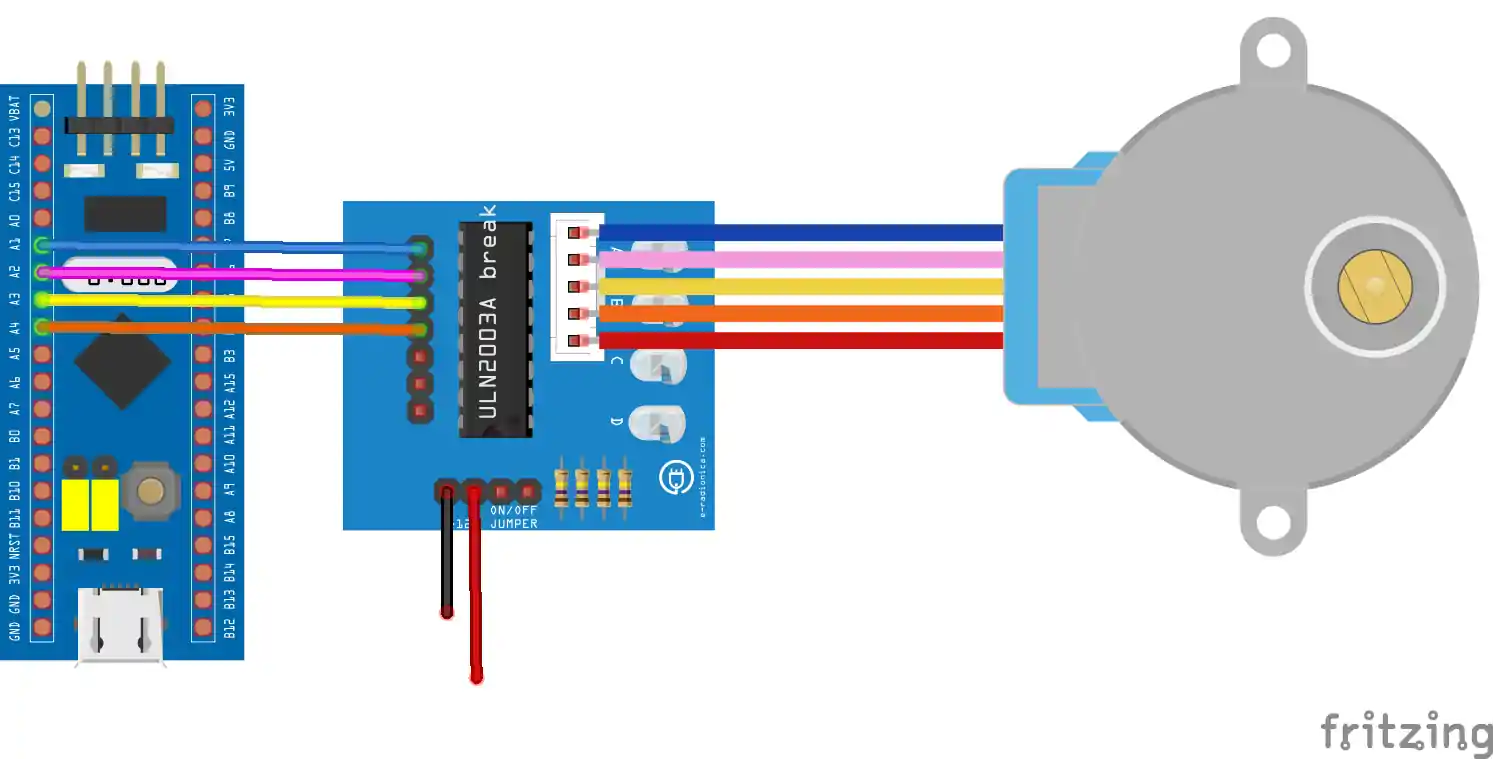
The ULN2003 driver connects the STM32 to the 28BYJ‑48 stepper motor, allowing safe control of the motor coils.
- IN1 to IN4 on the ULN2003 are connected to PA1, PA2, PA3, and PA4 on the STM32. These GPIOs send step signals to control the motor sequence.
- The driver is powered by 5V from an external battery, as the motor requires more current than the STM32 can supply.
- The 5-pin output header on the ULN2003 connects directly to the stepper motor, matching its socket.
Always connect the GND of the STM32 and the power source to the GND of the driver for proper operation.
STM32CubeMX Configuration
Clock Configuration
The image below shows the clock configuration in CubeMX.
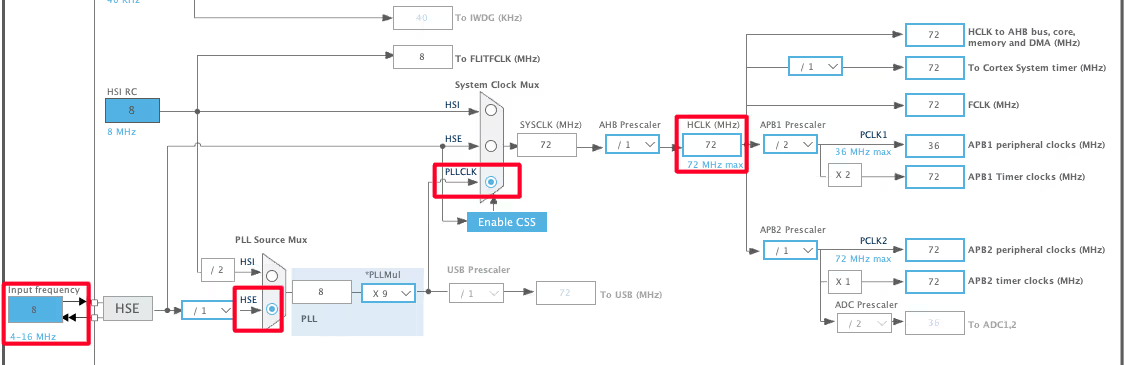
I am using the external crystal to provide the clock. The STM32F103C8 board has 8MHz crystal on it, and we will run the system at maximum 72MHz clock. Also note that the APB2 Timer clock is at 72MHz. This will be later used while configuring the timer.
Timer Configuration for delay
We need the delay in microseconds to control the RPM of the motor. I have already covered a tutorial about how to generate delays in microseconds. The image below shows the timer configuration for the delay.
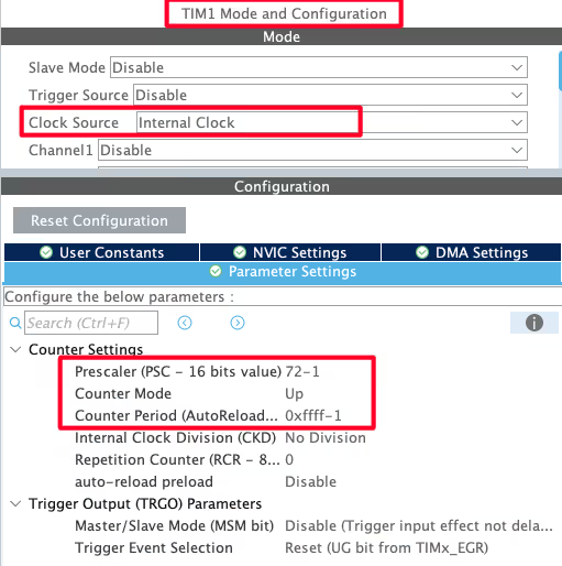
I am using TIM1 to provide the delay. The TIM1 is connected to the APB2 bus, which is running at 72MHz as shown in the clock configuration above.
We need the Timer frequency to be 1MHz, so we will use the prescaler of 72 to bring down the clock from 72MHz to 1MHz. The ARR is set to maximum, 0xFFFF, as it is generally set for delays.
Pin Configuration
The image below shows the pin configuration for this project.
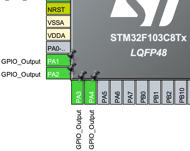
These pins, PA1 to PA4, are connected to the input of the driver ULN2003. I have set these pins as output.
Stepper Motor Control: Code Flow Explained
In this section we will drive the motor using Half Drive mode. We will also see how to generate the microsecond delay to control the angle of rotation.
Microsecond Delay
Below is the function to generate the delay in microseconds.
void delay (uint16_t us)
{
  __HAL_TIM_SET_COUNTER(&htim1, 0);
  while (__HAL_TIM_GET_COUNTER(&htim1) < us);
}When the function is called with the parameter as the number of microseconds, the following operations takes place
- The TIM1 counter will reset to 0.
- The counter will start counting up, till the value (us) has been reached.
- Once the value is reached, the function will exit.
As I mentioned before, each count takes 1 us, and therefore the counter will keep counting in microseconds until the input value has reached. Once it happens, the control will come out of the loop, and we have had achieved the delay.
If you don’t understand this part please check out https://controllerstech.com/create-1-microsecond-delay-stm32/
Defines
Define the number of steps the motor takes for 1 revolution. We will use the Half Drive in this tutorial, so we have a total of 4096 steps in 1 revolution.
#define stepsperrev 4096Now we will define the function to set the RPM of the Motor. We have to use it instead of delay.
void stepper_set_rpm (int rpm)  // Set rpm--> max 13, min 1,,,  went to 14 rev/min
{
	delay(60000000/stepsperrev/rpm);
}The parameter of the function stepper_set_rpm is the RPM with which we want the motor to rotate. This function basically generates a delay in microseconds, which depends on the 2 parameters. Here the value 60000000 represents the number of microseconds in 1 minute.
- The number of steps motor takes for 1 Revolution.
- The RPM of the motor we want.
Drive Stepper Motor
Next is the function to drive 1 sequence in the Half Drive Mode. In this mode, there are a total of 8 steps required to generate 1 sequence. We have to set the pins HIGH in a particular order, which is shown below.
void stepper_half_drive (int step)
{
  switch (step){
         case 0:
		  HAL_GPIO_WritePin(GPIOA, GPIO_PIN_1, GPIO_PIN_SET);   // IN1
		  HAL_GPIO_WritePin(GPIOA, GPIO_PIN_2, GPIO_PIN_RESET);   // IN2
		  HAL_GPIO_WritePin(GPIOA, GPIO_PIN_3, GPIO_PIN_RESET);   // IN3
		  HAL_GPIO_WritePin(GPIOA, GPIO_PIN_4, GPIO_PIN_RESET);   // IN4
		  break;

	  case 1:
		  HAL_GPIO_WritePin(GPIOA, GPIO_PIN_1, GPIO_PIN_SET);   // IN1
		  HAL_GPIO_WritePin(GPIOA, GPIO_PIN_2, GPIO_PIN_SET);   // IN2
		  HAL_GPIO_WritePin(GPIOA, GPIO_PIN_3, GPIO_PIN_RESET);   // IN3
		  HAL_GPIO_WritePin(GPIOA, GPIO_PIN_4, GPIO_PIN_RESET);   // IN4
		  break;

          case 2:
		  HAL_GPIO_WritePin(GPIOA, GPIO_PIN_1, GPIO_PIN_RESET);   // IN1
		  HAL_GPIO_WritePin(GPIOA, GPIO_PIN_2, GPIO_PIN_SET);   // IN2
		  HAL_GPIO_WritePin(GPIOA, GPIO_PIN_3, GPIO_PIN_RESET);   // IN3
		  HAL_GPIO_WritePin(GPIOA, GPIO_PIN_4, GPIO_PIN_RESET);   // IN4
		  break;

	  case 3:
		  HAL_GPIO_WritePin(GPIOA, GPIO_PIN_1, GPIO_PIN_RESET);   // IN1
		  HAL_GPIO_WritePin(GPIOA, GPIO_PIN_2, GPIO_PIN_SET);   // IN2
		  HAL_GPIO_WritePin(GPIOA, GPIO_PIN_3, GPIO_PIN_SET);   // IN3
		  HAL_GPIO_WritePin(GPIOA, GPIO_PIN_4, GPIO_PIN_RESET);   // IN4
		  break;

	  case 4:
		  HAL_GPIO_WritePin(GPIOA, GPIO_PIN_1, GPIO_PIN_RESET);   // IN1
		  HAL_GPIO_WritePin(GPIOA, GPIO_PIN_2, GPIO_PIN_RESET);   // IN2
		  HAL_GPIO_WritePin(GPIOA, GPIO_PIN_3, GPIO_PIN_SET);   // IN3
		  HAL_GPIO_WritePin(GPIOA, GPIO_PIN_4, GPIO_PIN_RESET);   // IN4
		  break;

	  case 5:
		  HAL_GPIO_WritePin(GPIOA, GPIO_PIN_1, GPIO_PIN_RESET);   // IN1
		  HAL_GPIO_WritePin(GPIOA, GPIO_PIN_2, GPIO_PIN_RESET);   // IN2
		  HAL_GPIO_WritePin(GPIOA, GPIO_PIN_3, GPIO_PIN_SET);   // IN3
		  HAL_GPIO_WritePin(GPIOA, GPIO_PIN_4, GPIO_PIN_SET);   // IN4
		  break;

	  case 6:
		  HAL_GPIO_WritePin(GPIOA, GPIO_PIN_1, GPIO_PIN_RESET);   // IN1
		  HAL_GPIO_WritePin(GPIOA, GPIO_PIN_2, GPIO_PIN_RESET);   // IN2
		  HAL_GPIO_WritePin(GPIOA, GPIO_PIN_3, GPIO_PIN_RESET);   // IN3
		  HAL_GPIO_WritePin(GPIOA, GPIO_PIN_4, GPIO_PIN_SET);   // IN4
		  break;

	  case 7:
		  HAL_GPIO_WritePin(GPIOA, GPIO_PIN_1, GPIO_PIN_SET);   // IN1
		  HAL_GPIO_WritePin(GPIOA, GPIO_PIN_2, GPIO_PIN_RESET);   // IN2
		  HAL_GPIO_WritePin(GPIOA, GPIO_PIN_3, GPIO_PIN_RESET);   // IN3
		  HAL_GPIO_WritePin(GPIOA, GPIO_PIN_4, GPIO_PIN_SET);   // IN4
		  break;

	}
}Once all these 8 steps are executes, 1 sequence will complete and the motor will rotate through an angle of 360/512 = 0.703125°.
Control Stepper Angle
The motor takes 512 sequences to complete 1 revolution. This means in each sequence, the motor rotates through an angle of 360/512 = 0.703125°. Now we will write a function to control the angle of rotation.
Below is the function to move the stepper by some angle. Here we can also control the direction and RPM.
void stepper_step_angle (float angle, int direction, int rpm) //direction-> 0 for CK, 1 for CCK
{
  float anglepersequence = 0.703125;  // 360 = 512 sequences
  int numberofsequences = (int) (angle/anglepersequence);
  for (int seq=0; seq<numberofsequences; seq++)
  {
	if (direction == 0)  // for clockwise
	{
       	  for (int step=7; step>=0; step--)
	  {
	    stepper_half_drive(step);
	    stepper_set_rpm(rpm);
	  }
	}
	else if (direction == 1)  // for anti-clockwise
	{
	  for (int step=0; step<=7; step++)
	  {
	    stepper_half_drive(step);
	    stepper_set_rpm(rpm);
	  }
	}
  }
}Inside this function we will first calculate the number of sequence required. This depends on the Angle through which we want to rotate the motor. numberofsequences = angle/0.703125.
Then we will call the function stepper_half_drive to drive the motor for 1 sequence. This will be repeated as many times as the numberofsequences we have.
We can also control the direction of rotation of motor by reversing the steps in each sequence.
Control Stepper Angle considering current position
The function stepper_step_angle can rotate the motor through an angle, but it does not consider the current position of the stepper motor. For eg– if you pass the angle 45 to the parameter and call the function twice, the motor will rotate through an angle of 90°.
We will write another function to rotate the motor through an angle, which will also consider the current position of the motor.
float currentAngle = 0;
void Stepper_rotate (int angle, int rpm)
{
	int changeinangle = 0;
	changeinangle = angle-currentAngle;  // calculate the angle by which the motor needed to be rotated
	if (changeinangle > 0.71)  // clockwise
	{
		stepper_step_angle (changeinangle,0,rpm);
		currentAngle = angle;  // save the angle as current angle
	}
	else if (changeinangle <0.71) // CCK
	{
		changeinangle = -(changeinangle);
		stepper_step_angle (changeinangle,1,rpm);
		currentAngle = angle;
	}
}The variable currentAngle is defined as global variable and it will keep track of the current position of the motor.
Inside the function Stepper_rotate, we will first calculate the changeinangle. If this change is greater than 0.71, we will call the function stepper_step_angle to rotate the motor in the clockwise direction.
Similarly, If this change is lesser than -0.71, we will call the function stepper_step_angle to rotate the motor in the counterclockwise direction.
The value 0.71 is chosen because the motor rotates through 0.703125° in 1 sequence. Therefore we can not rotate the motor through an angle, which is lesser than this value.
The main function
int main()
{
  ....
  HAL_TIM_Base_Start(&htim1);
  while (1)
  {
    for (int i=0; i<=360; i++)
    {
      Stepper_rotate(i, 10);
      HAL_Delay(250);
    }
    for (int i=360; i>=0; i--)
    {
      Stepper_rotate(i, 10);
      HAL_Delay(250);
    }
  }
} Inside the main function we will start the timer, so to enable the delay function.
In the while loop we will call the function Stepper_rotate in a for loop to rotate the motor through the entire 360°. The motor will wait for 250ms between each angle. Once the motor reached 360°, it will start rotating in the counterclockwise direction.
VIDEO TUTORIAL
STM32 Stepper Motor (28BYJ-48) Tutorial Video
This tutorial shows how to interface and control a 28BYJ-48 stepper motor with an STM32 microcontroller using the ULN2003 driver and STM32CubeIDE. You’ll learn the wiring, CubeMX configuration, and how to control motor direction, speed, and rotation angle using different stepping modes. A step-by-step video walkthrough is included to help you follow along easily.
Watch the VideoConclusion
In this tutorial, we learned how to control a 28BYJ-48 stepper motor using an STM32 microcontroller with the help of the ULN2003 driver. We started by understanding how the stepper motor and driver work, then moved on to the wiring and STM32CubeMX configuration. After that, we implemented the code to run the motor in different modes like wave drive, full drive, and half-step drive, and also learned how to control the motor speed, direction, and rotation angle.
This is useful because stepper motors are widely used where accurate movement is required, such as in robotics, automation, and positioning systems. The methods shown in this tutorial help you get smooth and precise control of the motor using simple GPIOs and timers. Overall, this tutorial gives a clear and practical starting point for anyone who wants to work with stepper motors using STM32 and build more advanced motion-control projects later.
Checkout More STM32 Tutorials
How to Control a Servo Motor with STM32 using PWM
STM32 OTA Bootloader (PART 7): Wireless Firmware Update Using ESP8266 WiFi Module
Send and Receive data from the WebServer using STM32
How to Interface SHT21 Sensor with STM32 using I2C (Step-by-Step with Code and Circuit Diagram)
FreeRTOS Tutorials #8 -> Software Timers
How to use DAC in STM32

HI this code is not working on Nucleo board L073RZ i have used the same code and made necessary changes but the stepper motor is not rotating, atleast itsnot vibrating, the stepper motor with ULN2003AN is working fine with ESP32
The code works well if you want to move the motor for a number of sequences. How would one move steps less than a sequence? Lets say I want to move 5 steps, which is less than a full sequence, how will this be done? Or if I want to move 9 steps, which is one full sequence plus one step.
Hi,
I have copied the code as is and made the connections which I have double checked. When I run the code, my motor vibrates but doesn’t rotate.
I have tested with two different motors and driver boards but no luck.
Can anyone please help.
Resolved the issue. My wiring was not right. Swapper IN1 and IN2 and the motor started rotating.
Hi, what is that 60000000 in delay function that is used in stepper_set_rmp function?
from where that number is written?
Hi, my motor is vibrating but no rotating, do you know why ?
Did you solve ur problem?
Check your wire connection
Can you suggest me what I need to drive three stepper motors with stm32f1
well 4 pins are used to drive 1 motor. So you need to use 12 pins
Couldn’t download the stepper motor code. I guess the application/user folder is missing. The download contains only the auto generated Core and driver folders.
check the main.c file
What consideraions should we have when we work with a NEMA 17.
I couldn’t do the connection, can you help me
What’s there to do the connection? Stepper comes along a fixed connector, and you can connect it only one way.
Is it possible to reverse direction of the rotation?
yes. In thew function stepper_step_angle , second parameter is direction. I have commented the values in the code.
1
your mathematic ist wrong
Ok. Can u elaborate ?
where is your Main function?
you can download the entire code.