How to communicate between HC-12 using STM32
HC-12 wireless serial port communication module is a new-generation multichannel embedded wireless data transmission module. Its wireless working frequency band is 433.4-473.0MHz, multiple channels can be set, with the stepping of 400 KHz, and there are totally 100 channels. The maximum transmitting power of module is 100mW (20dBm), the receiving sensitivity is -117dBm at baud rate of 5,000bps in the air, and the communication distance is 1,000m in open space.
I will be using the modules in the default setup. The parameters are as shown below
- Here Baud Rate is 9600
- Channel selected is1
- Transmitting Power is 20dBm
- and mode selected is FU3
you can see the datasheet for more information on how to change these parameters. But i think the default setup is pretty good and it gives you a fairly good communication range also.
VIDEO TUTORIAL
You can check the video to see the complete explanation and working of this project.
Check out the Video Below
CubeMX Setup
I am going to use the Uart Ring Buffer to communicate between the two HC-12 modules. These modules will be connected to the 2 different microcontrollers, and both of them will be using the same code. And that’s why I will just show the CubeMX setup for only one of them
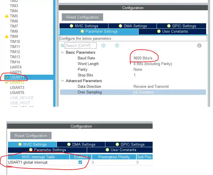
Above is the Setup for the UART1, where the HC-12 will be connected. I have selected the baud rate of 9600 as HC-12 is working at same Baud Rate. Also make sure that you turn on the interrupt. The connection between HC-12 and Microcontroller will be shown below in the connection section
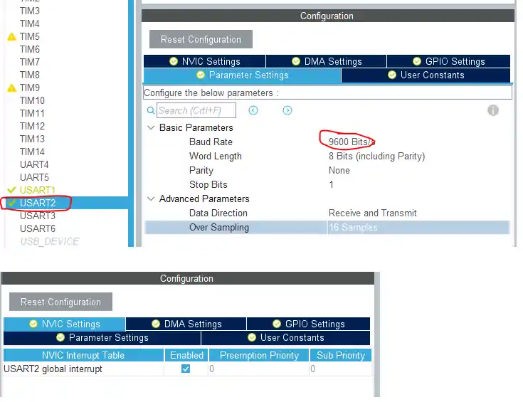
Above is the setup for UART2, which is connected to the computer
The exact same setup is needed for the second microcontroller too. For more information, check the video at the end of this post.
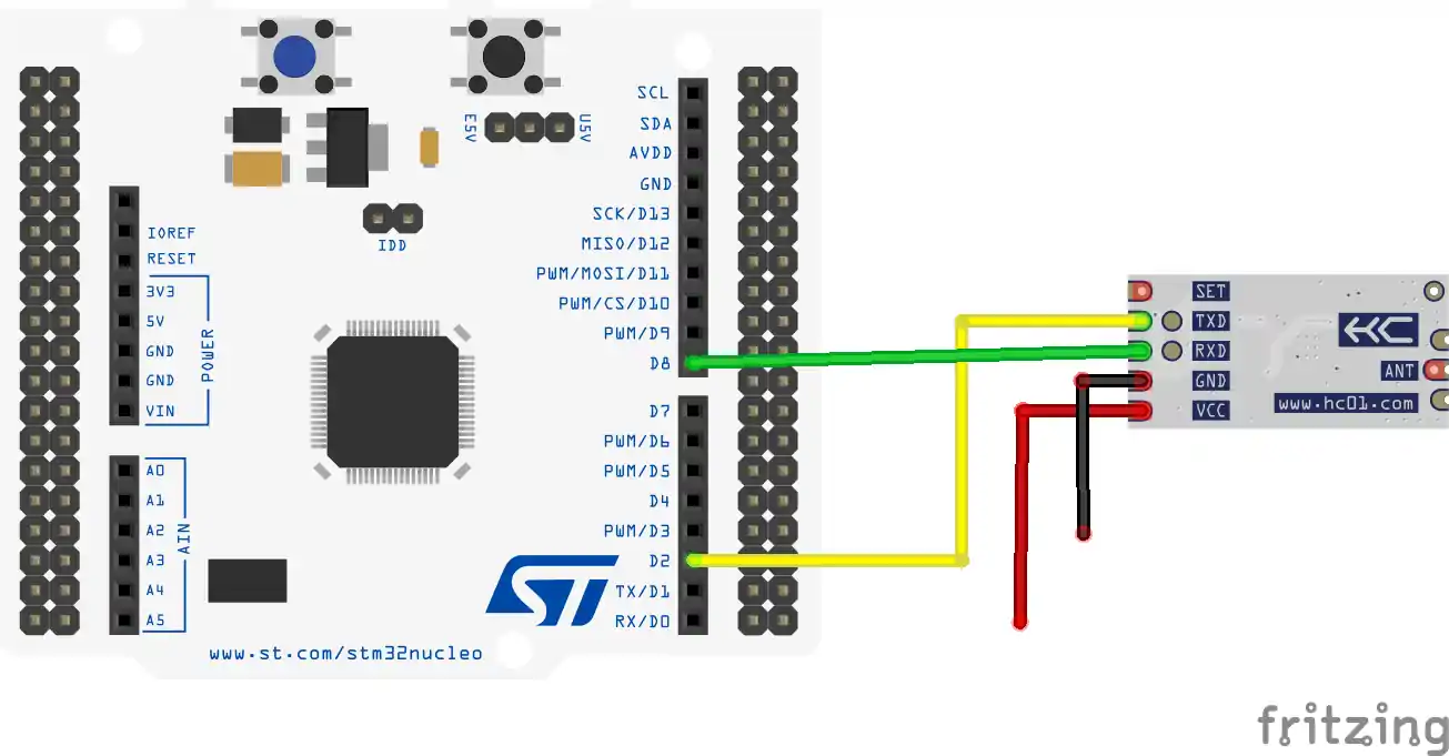
Connection
- Vcc is connected to 5V
- Gnd to Gnd
- Tx from the HC-12 is connected to the Rx from the MCU
- and Rx from HC-12 to Tx from the MCU
- SET pin must be left as it is for communication, and while using AT commands, we must Ground it
Those, who have errors in the Uart_isr function, like DR or SR registers are not present, or L4 series and G series MCUs have some issues with UART_ISR_TXE. To resolve them, visit https://controllerstech.com/managing-multiple-uarts-in-stm32/
and do what the UPDATE section have mentioned
Some Insight into the code
After generating the project, you have to include the library files into the project. Basically UartRingbuffer_multi.c file will go in the src folder and UartRingbuffer_multi.h file will go in the inc folder.
First of all I have defined the new names to the UART handlers as shown below
#define device_uart &huart1
#define pc_uart &huart2Next we need to initialize the ring buffer in the main function
Ringbuf_init();In the while loop, if the controller receives the data from device, it will send it to the PC. And if it receives the data from the PC, it will send it to the device. This way it will act as a mediator in between device and computer.
 while (1)
  {
    if (IsDataAvailable(pc_uart))
    {
     int data = Uart_read(pc_uart);
     Uart_write(data, device_uart);
    }

    if (IsDataAvailable(device_uart))
    {
     int data = Uart_read(device_uart);
     Uart_write(data, pc_uart);
    }
}Result
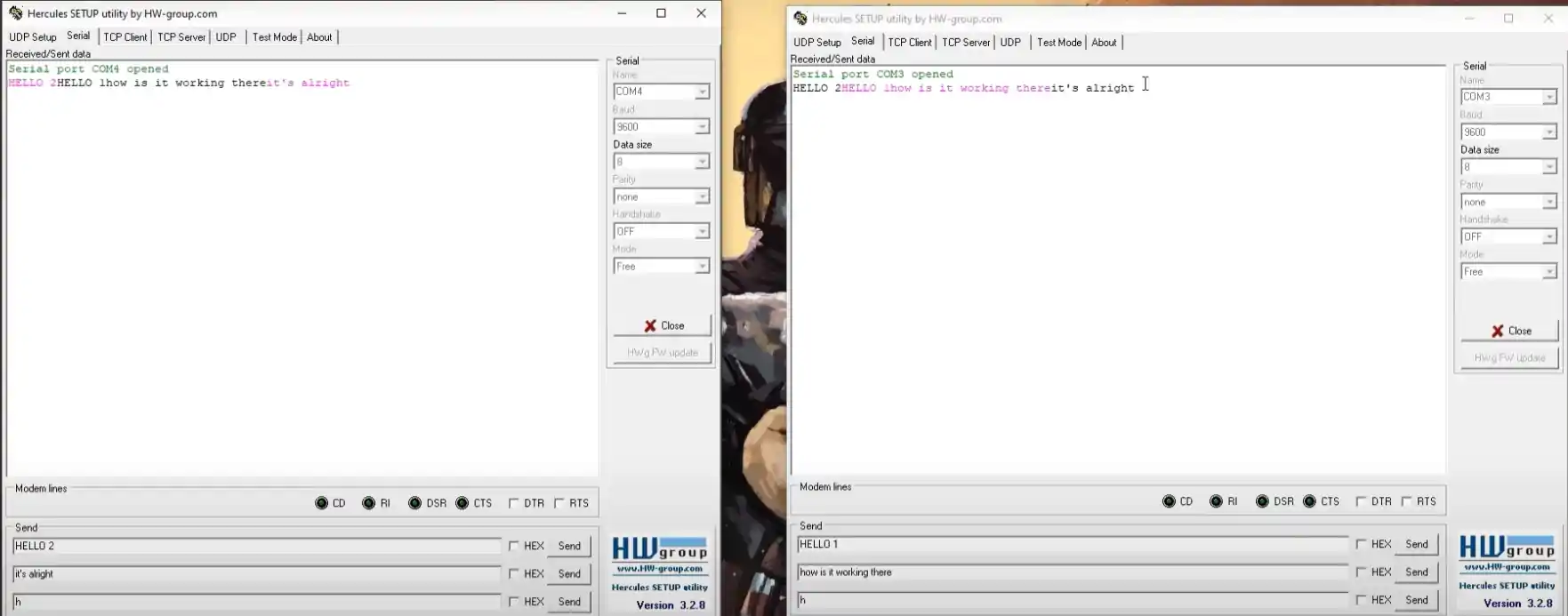
- In the above picture, both the MCUs are using different com ports.
- The Pink color is the one you send, and the black color is the one receive.
- As you can see, the data sent from the first MCU is being received by the second, and vice versa
Info
You can help with the development by DONATING Below.
To download the project, click the DOWNLOAD button.


Can you make a tutorial to put the stm32 and hc12 on sleep mode when no data is being received from the transmitter. It would be great.
thanks for your best tutorial if you can run remote code learn ev1527 with remote and teach us how to run it thanks from you
every day i see your site and check for best new tutorial from you and every where i share your site link such as in telegram and other ilk because i think its the best site for reciving the best tutorial thanks my best friend
i wish longevity and healthy for you
thanks for the kind words.
Regarding ev1527, i don’t have it, and i am not in a location where i can buy that too. SO probably it won’t happen anytime soon.
Although you can refer datasheet or some arduino codes to get an idea of how it works
thanks my best friend
Dear Sir,
Thanks for your efforts.
This is one of the best website to learn STM32 in Internet from beginner to Advanced.
So glad that you could help me to Learn STM32.