Getting started with Riverdi STM32 Embedded Display
This tutorial will cover how to run our first project in the STM32 Embedded displays provided by the Riverdi. They are specialized in manufacturing different kind of displays, which includes the STM32 based display that supports the TouchGFX. The display can be purchased from https://riverdi.com/product-category/stm32-embedded-displays
Using TouchGFX as the designer software gives it edge over some other intelligent displays you might have used so far that lacks a solid designer. Also having STM32H7 at the core is another advantage since we know how capable this MCU is.
Not only it can be used for interfacing the display but we also have all sort of peripherals available to interface other devices like CAN, ADD, DAC, UART, I2C, SPI, etc.
Let’s see how to run our first project on this Riverdi display.
VIDEO TUTORIAL
You can check the video to see the complete explanation and working of this project.
Connection
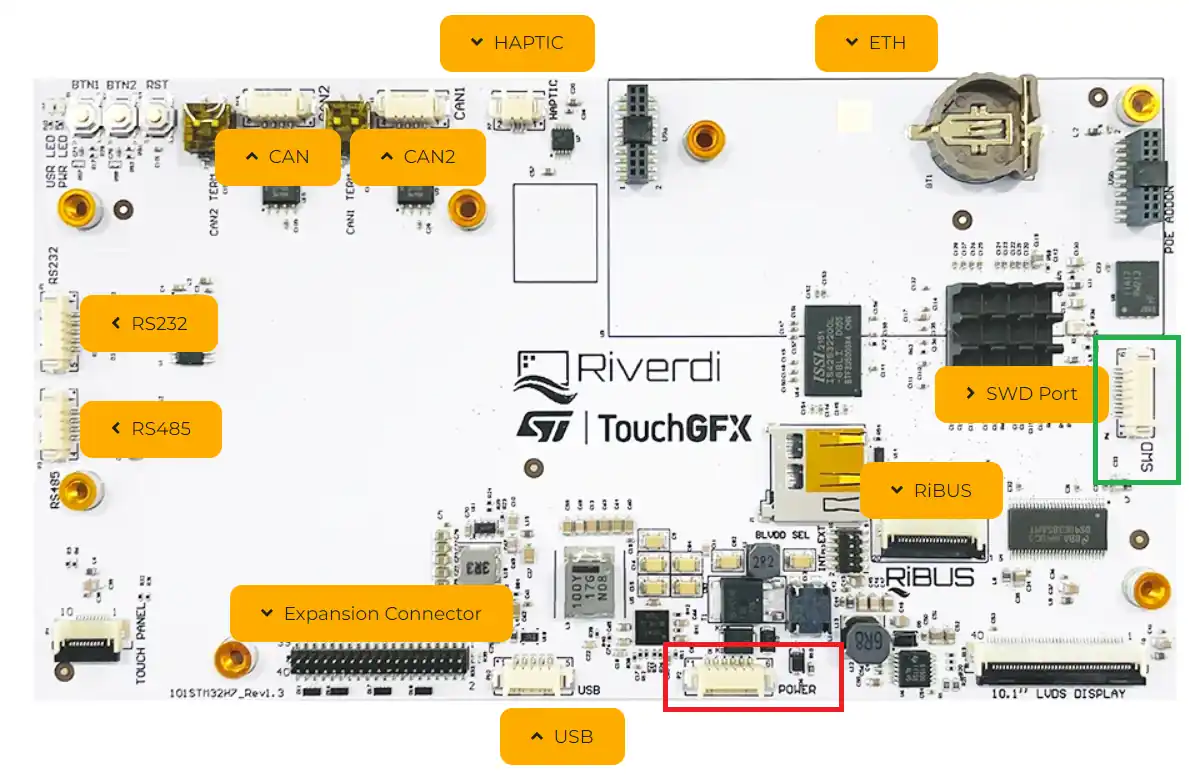
Since this is going to be a very basic project, I am not going to connect any external device to it. So for the basic connection we only need to connect the power and the ST link.
I have highlighted the Power and SWD ports in the picture above.
Below the picture, from datasheet of the display, shows the pinouts for these ports.
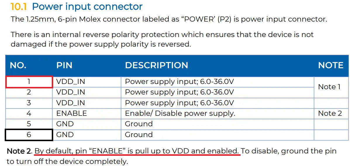
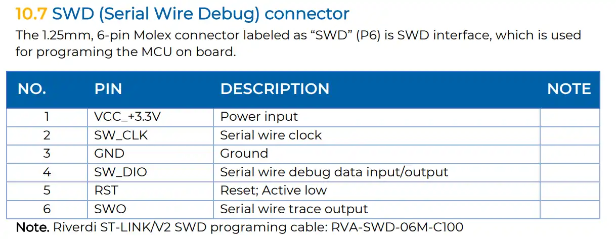
I have made the connection as per the pin description given in the pictures above.
For the Power connector I have only connected the VCC to pin 1 and GND to pin 6. And for the SWD, I have connected all 6 pins to the respective pins of the ST link.
TouchGFX Design
Note:- You need to have a minimum of TouchGFX Version 4.20.
Below is the image showing how to create the project.
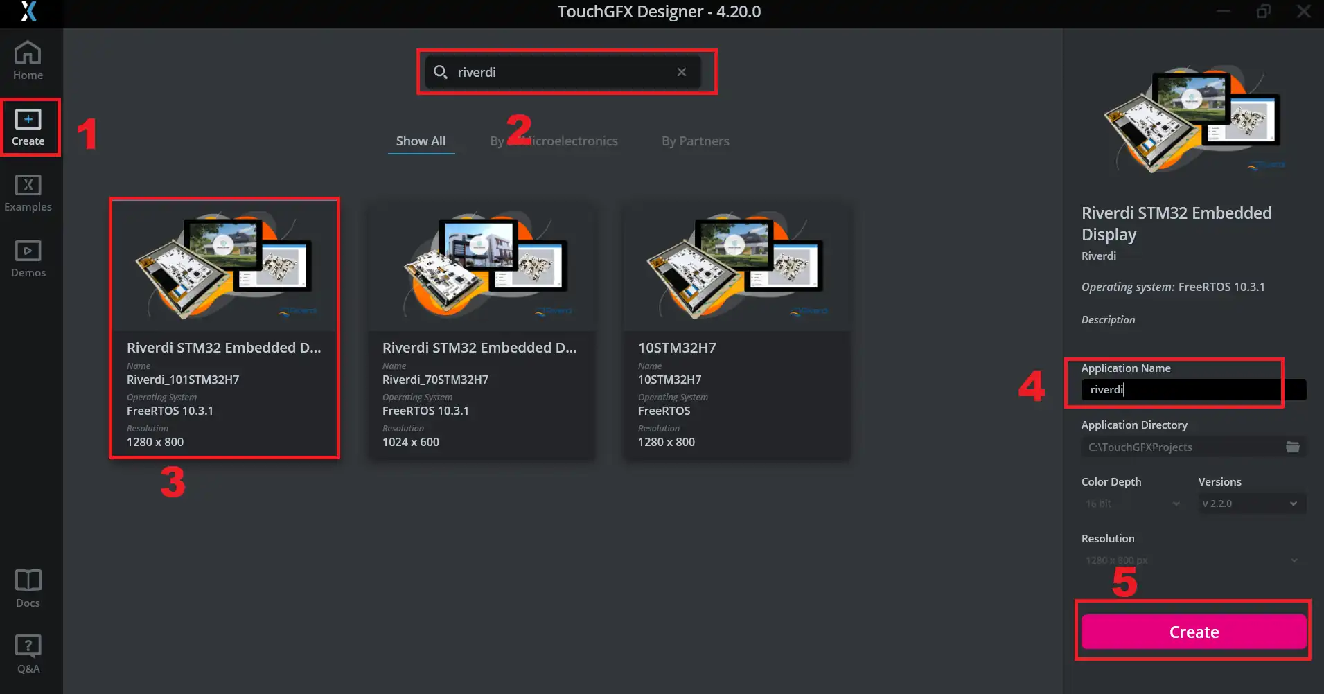
- click create to create a new project
- Search for the Riverdi to see the available boards
- Choose the display you have. I have the 10.1″ display, so I am choosing 101STM32H7
- Give the name to the project
- Click create to create the project.
Add Background Image
Below are the steps shows to add the background image. I already have the image of the same resolution as the display in PNG format.
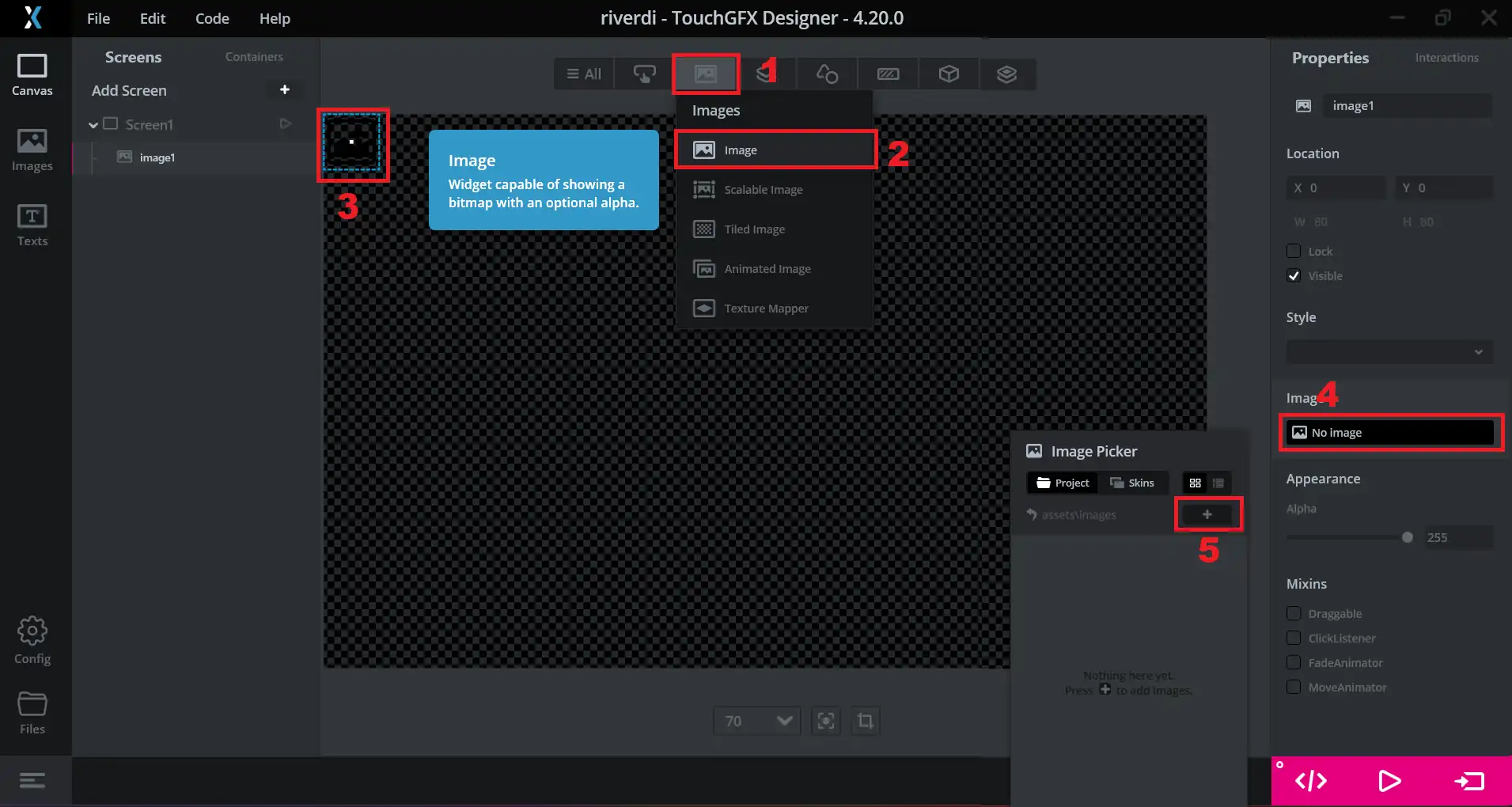
- click on the image tab
- select the image widget
- click on the empty image to see its properties
- In the image section, click on no image
- click the add(+) button to add the image.
Now browse the image and add it to the project.
Add the widgets
We will also add some widgets to this project. I am going to add a slider and a gauge. The Idea is simple, I want the gauge to rotate as according to how we move the slider.
Below are the images showing the slider and gauge configurations.
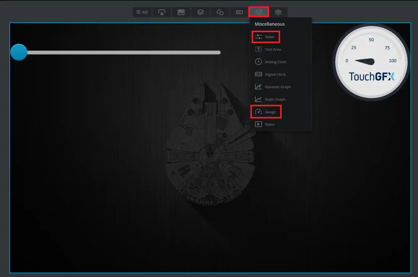


Basically I have added the slider and the gauge to the screen. The slider ranges from 0 to 100, and so does the gauge. This is to make sure the uniformity between them.
Add the interaction
Now in the end we will add one interaction to this screen. To do that you have to click on interaction, then click on the + button.
Now click on the interaction to configure it.
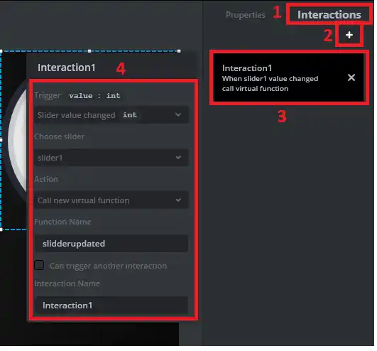
- The interaction will trigger whenever the slider’s value is changed.
- This will call a new virtual function, whose name I have set as sliderupdated.
- We will later write this function in the IDE.
Generate the code
Now everything is finished, so we will generate the code by clicking the generate button as shown in the picture below.
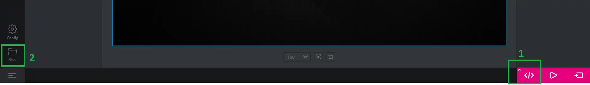
Once the code is generated, we will open it in the cube IDE.
Click on the files button as shown in the picture above. This will open the project folder.
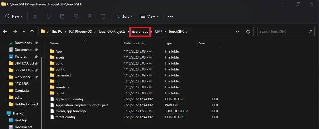
- Now go back to main project folder.
- Here you will see the cubeIDE folder, so open it.
- There you will find the project file, which can be opened with the cubeIDE.
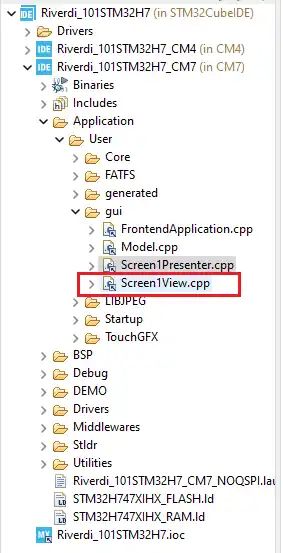
The code
We only need to write a small code in the Screen1view.cpp file. You can see the location of the fille in the project structure.
We need to first define the sliderupdated function we created (in the interaction) inside the header file.
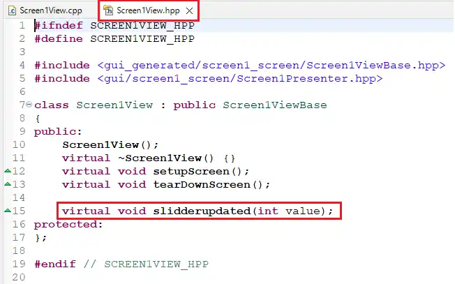
Now we will create this function in the source file and write the code inside it.
void Screen1View::slidderupdated(int value)
{
	gauge1.setValue(value);
	gauge1.invalidate();
}Here the slidderupdated function will be called whenever the slider reports a new changed value.
We will simply call setvalue function to set the value to the gauge. And the invalidate function will be called for the new value to take effect.
Load the project to display
You can not load the project using cube IDE. You have to either use the cube programmer or the touch GFX itself.
In either of the cases, we first need to copy the external loader file into the cube programmer directory.
The external loader file can be found inside the project we created. Its location is shown below
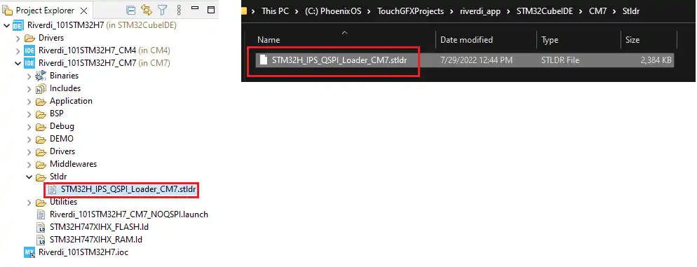
We just need to copy this file inside the cube programmer directory. In my case it is C:\Program Files\STMicroelectronics\STM32Cube\STM32CubeProgrammer\bin\ExternalLoader
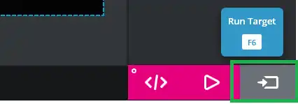
Once the loader has been copied, restart the touch GFX so that it can see the new loader.
Now click run target to load the project into the display.
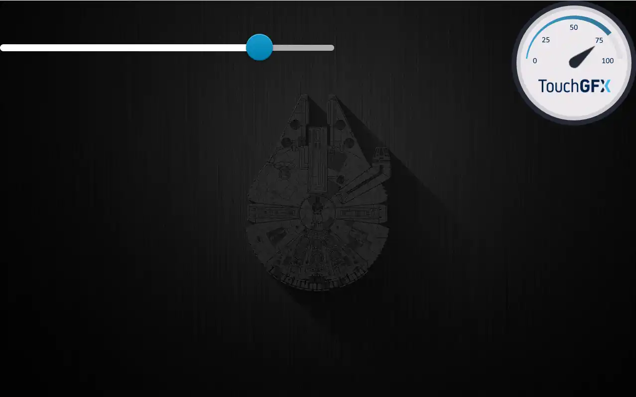
Result
Below are the images showing the slider position along with the gauge position.