Last Updated: February 6, 2026
ESP32 ADC Continuous Mode Guide
Learn to configure ESP32 ADC in continuous mode using DMA and interrupts in ESP‑IDF. This tutorial includes code setup, callback, and data handling. The project is available to download at the end of this post.
Recommended resources:
This is the 9th tutorial in the ESP32 series using the espressif-IDF and and 2nd in the mini series covering ADC peripheral in ESP32.
Please take a look at the following before continuing with this one:
VIDEO TUTORIAL
You can check the video to see the complete explanation and working of this project.
Introducing the ADC peripheral in ESP32
The Analog-to-Digital Converter (ADC) in the ESP32 is a built-in hardware module that enables the conversion of analog voltage signals into digital values for further processing in firmware. This allows the ESP32 to read input from analog sensors like temperature, light, potentiometers, and more. The ESP32 features two ADC peripherals, ADC1 and ADC2, which together provide multiple input channels and flexible configuration options.
The ADC hardware in ESP32 supports various modes of operation such as one-shot mode, continuous mode, and DMA mode (on newer chips), making it suitable for both low-latency and high-throughput applications.
ESP32 has 2 ADC units, which can be used in scenarios like:
- Generate one-shot ADC conversion result
- Generate continuous ADC conversion results
Below is the image showing the ADC channels on the ESP32 dev board.
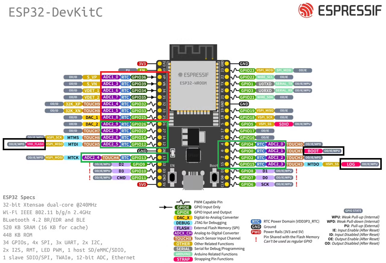
The Red box in the image above highlights the ADC1 channels, whereas the Green box highlights the ADC2 channels. We can use either of these ADC units. Just try to avoid the pins highlighted with Black box. These are the strapping pins which are used during flashing the chip. Therefore in order to use these pins for some other purpose, they require additional configuration.
I am going to read the ADC1 channel 0 (VP) and channel 3 (VN) using the ADC in Continuous mode. We will again use the 2 channels of ADC1. These channels will keep converting in the background and we can read their data at any point in our code.
WIRING DIAGRAM
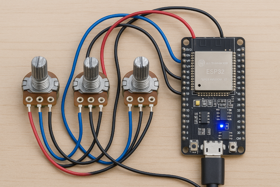
Below is the image showing the potentiometers connected to the ESP32 board.
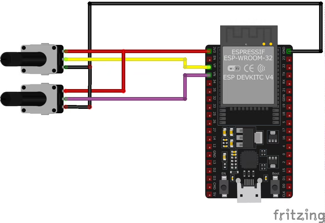
Both the potentiometers are connected between 3.3V and gnd of the ESP32 board. The out pins from the potentiometers are connected to the ADC1 Channel 0 (VP) and Channel 3 (VN).
THE CODE
Global Definitions
Below are some definitions that we will use in the entire code.
adc_channel_t channels[2] = {ADC1_CHANNEL_0, ADC1_CHANNEL_3};
int ADC_DATA[2];
int voltage[2];

adc_continuous_handle_t adc_handle;
TaskHandle_t cb_task;- The channels array stores the channels that we will convert using the Continuous mode.
- The adc_handle is the ADC Continuous handle which will be used throughout the code.
- adc_raw[2] is an array to store the RAW data for both the channels.
- voltage[2] is an array to store the converted voltage data for both channels.
- cb_task is the handle of the callback task. We will use this task to extract the channel’s raw data whenever the conversion is finished.
ADC Initialization
We will break down the initialization function into multiple parts. Let’s start with ADC handle initialization.
ADC Handle Initialization
adc_continuous_handle_cfg_t handle_config = {
	.conv_frame_size = 12,
	.max_store_buf_size = 24,
};
ESP_ERROR_CHECK(adc_continuous_new_handle(&handle_config, &adc_handle));The structure handle_config stores all the important information about the ADC Handle. The members of this structure are mentioned below:
- conv_frame_size is the size of conversion frame in Bytes.
- max_store_buf_size is the maximum data bytes the ADC buffer is allowed to store.
The function adc_continuous_new_handle initializes the ADC handle configured in the above structure. It also takes the pointer to the ADC continuous handle as the parameter.
Let’s understand what the above parameters mean.
Each conversion result occupies SOC_ADC_DIGI_RESULT_BYTES bytes. The variable SOC_ADC_DIGI_RESULT_BYTES is defined in soc/soc_caps.h file. In case of ESP32, the value of this variable is 2.
Each conversion frame consists of multiple conversion results. Each time one conversion frame is generated, an interrupt will trigger suggesting the conversion is complete. The conversion frame size should be declared in multiple of SOC_ADC_DIGI_DATA_BYTES_PER_CONV. This variable is again defined in soc/soc_caps.h file. In case of ESP32, the value of this variable is 4.
In the above case, I have defined the max_store_buf_size to 24 bytes. This means I want the ADC to sample 12 conversions (24/SOC_ADC_DIGI_RESULT_BYTES). Although the conv_frame_size is set to 12 bytes, which means one conversion frame can store 6 conversion results (12/SOC_ADC_DIGI_RESULT_BYTES). The rest of the 6 conversions will be in the queue and will be handled next time the interrupt is triggered.
Continuous mode configuration
adc_continuous_config_t adc_config = {
.pattern_num = numChannels,
.conv_mode = ADC_CONV_SINGLE_UNIT_1,
.format = ADC_DIGI_OUTPUT_FORMAT_TYPE1,
.sample_freq_hz = 20*1000,
};The structure adc_config stores all the information about the ADC Continuous Mode Driver. The members of this structure are mentioned below:
- pattern_num is the number of channels we want to convert.
- conv_mode configures the ADC units. We can use single ADC unit or multiple units simultaneously or alternatively. Here I am using only ADC1.
- format configures the output data type format. In Type1 format, the output data consists of channel number and the data for the corresponding channel. Whereas in Type2 format, the output data consists of the channel number, data for the corresponding channel and the ADC unit as well.
- sample_freq_hz is the sampling frequency. I have set it to 20 KHz and this is the minimum sampling frequency allowed on ESP32. You can check the threshold values in soc/soc_caps.h file.
We still need to configure the channels. The code below is continuation of the adc_config structure.
adc_digi_pattern_config_t adc_channel_config[SOC_ADC_PATT_LEN_MAX] = {0};
for (int i=0; i<numChannels; i++)
{
adc_channel_config[i].channel = channels[i];
adc_channel_config[i].atten = ADC_ATTEN_DB_12;
adc_channel_config[i].bit_width = ADC_BITWIDTH_12;
adc_channel_config[i].unit = ADC_UNIT_1;
}
adc_cnfig.adc_pattern = channel_config;The structure adc_channel_config stores the information about the ADC channels. The members of this structure are mentioned below:
- channel contains the ADC channel number, which is being configured.
- atten is the voltage attenuation to be used before it is input to the ADC. I am using the attenuation of 12dB, which allows us to measure voltages up to 2450mV. The details for the attenuation is shown in the image below.
- bitwidth is the resolution for the channel. It ranges from 9Bits to 13 Bits. The higher the resolution the precise is the measurement, but it also takes more time to convert the respective channel. I am using the 12bits resolution.
- unit is the ADC unit for the above channel.
After configuring the channels we will assign the structure channel_config to the adc_pattern structure of the adc_config structure.
We have all the configuration needed for the continuous mode driver, so we will pass the configuration to the adc_continuous_config function.
ESP_ERROR_CHECK(adc_continuous_config(adc_handle, &adc_cnfig));callback Configuration
adc_continuous_evt_cbs_t cb_config = {
.on_conv_done = callback,
};
ESP_ERROR_CHECK(adc_continuous_register_event_callbacks(adc_handle, &cb_config, NULL));The structure cb_config configures the callback handling for the ADC. After a conversion frame is generated (.on_conv_done), a callback is called. This callback is defined as the function callback in the structure.
We call the function adc_continuous_register_event_callbacks to register the callback.
Final ADC Initialization Function
Below is the ADC initialization function, which is a combination of everything we discussed above.
void ADC_Init (adc_channel_t *channels, uint8_t numChannels)
{
// handle configuration
adc_continuous_handle_cfg_t handle_config = {
	.conv_frame_size = 12,
	.max_store_buf_size = 24,
};
ESP_ERROR_CHECK(adc_continuous_new_handle(&handle_config, &adc_handle));
// ADC Configuration with Channels
adc_continuous_config_t adc_cnfig = {
.pattern_num = numChannels,
.conv_mode = ADC_CONV_SINGLE_UNIT_1,
.format = ADC_DIGI_OUTPUT_FORMAT_TYPE1,
.sample_freq_hz = 20*1000
};
adc_digi_pattern_config_t channel_config[2];
for (int i=0; i<numChannels; i++)
{
channel_config[i].channel = channels[i];
channel_config[i].atten = ADC_ATTEN_DB_12;
channel_config[i].bit_width = ADC_BITWIDTH_12;
channel_config[i].unit = ADC_UNIT_1;
}
adc_cnfig.adc_pattern = channel_config;
ESP_ERROR_CHECK(adc_continuous_config(adc_handle, &adc_cnfig));
// Callback Configuration
adc_continuous_evt_cbs_t cb_config = {
	.on_conv_done = callback,
};
ESP_ERROR_CHECK(adc_continuous_register_event_callbacks(adc_handle, &cb_config, NULL));
}The Callback Handling
When one conversion frame is generated, a callback is called. Below is the callback function used to handle the callback.
The Callback function
static bool IRAM_ATTR callback (adc_continuous_handle_t handle, const adc_continuous_evt_data_t *edata, void *user_data)
{
	BaseType_t mustYield = pdFALSE;
	vTaskNotifyGiveFromISR(cb_task, &mustYield);
	return (mustYield == pdTRUE);
}We will give the attribute IRAM_ATTR to the callback function so that it can work in the Internal Ram. We should try to keep the callback function as short as possible. Therefore we will simply notify the callback task (cb_task) here.
The function vTaskNotifyGiveFromISR is used to pass the notification to the cb_task handle. It is intended for use when task notifications are used as light weight and faster binary or counting semaphore equivalents.
The callback task
The callback task will extract the data from the buffer and store the data in the desired locations.
void cbTask (void *parameters)
{
	uint8_t buf[30];
	uint32_t rxLen = 0;
	for (;;)
	{
		ulTaskNotifyTake(pdTRUE, portMAX_DELAY);
		adc_continuous_read(adc_handle, buf, 12, &rxLen, 0);
		for (int i=0; i<rxLen; i+=SOC_ADC_DIGI_RESULT_BYTES)
		{
			adc_digi_output_data_t *p = (adc_digi_output_data_t *)&buf[i];
			uint16_t channel = p->type1.channel;
			uint16_t data = p->type1.data;
			if (channel == ADC1_CHANNEL_0) ADC_DATA[0] = data;
			if (channel == ADC1_CHANNEL_3) ADC_DATA[1] = data;
		}
	}
}Here we will first call the function ulTaskNotifyTake, which will wait indefinitely (portMAX_DELAY) for the notification. Once the notification is sent by the callback function, the cbTask will resume its operations. It will perform the operation once and then it will again go in the waiting mode.
The function adc_continuous_read is used to read the data from the ADC. The parameters of this function are as follows:
- @param[in] handle is the ADC continuous mode driver handle. In this case we are using adc_handle.
- @param[out] buf is the Conversion result buffer to read from ADC. This is where the data will be stored into and it is defined in the cbTask itself.
- @param[in] length_max is the Expected length of the Conversion Results read from the ADC, in bytes. It is set to 12 bytes.
- @param[out] out_length is the Real length of the Conversion Results read from the ADC via this API, in bytes. We will store this length in the rxLen variable. The number of conversions is rxLen/SOC_ADC_DIGI_RESULT_BYTES.
- @param[in] timeout_ms is the Time to wait for data via this API, in millisecond. I am setting it to 0, so there is no wait time.
We know that each conversion result occupies 2 bytes (SOC_ADC_DIGI_RESULT_BYTES) in the buffer. Therefore the for loop increments by 2.
Inside the for loop we will first copy the data from the buffer to the adc_digi_output_data_t structure. The data structure is of format TYPE1, therefore the 2 bytes of data contains the ADC channel and ADC data.
We will then extract the channel and data from the data structure and store them in the relevant variables.
Finally store the ADC1_CHANNEL_0 data in the ADC_DATA[0] and ADC1_CHANNEL_3 data in the ADC_DATA[1] positions.
The main function
void app_main(void)
{
	xTaskCreate(cbTask, "Callback Task", 4096, NULL, 0, &cb_task);
	ADC_Init(channels, 2);
	ESP_ERROR_CHECK(adc_continuous_start(adc_handle));
	while (1)
	{
		voltage[0] = ADC_DATA[0]*3300/4095;
		voltage[1] = ADC_DATA[1]*3300/4095;
		printf("CH0:%d\t CH3:%d\t mV[0]:%d\t mV[3]:%d\n",ADC_DATA[0], ADC_DATA[1], voltage[0], voltage[1]);
		vTaskDelay(pdMS_TO_TICKS(100));
	}
}Inside the main function we will first create the callback Task.
- cbTask is the Taskcode for the callback task.
- “Callback Task” is the name for it.
- 4096 is the stack size for this task.
- We will not pass any parameters to the task.
- The priority is set to 0 and cb_task is the task handle.
After creating the task, we will call the function ADC_Init is used to initialize the ADC and its channels. The parameters of this function are as follows:
- 2 is the number of channels we want to read.
- channels is the channel array we defined globally. It contains the ADC channels we want to read.
Next we will call the function adc_continuous_start to start the ADC conversion. Once a conversion frame is generated, the callback will be called. The callback will notify the callback task and the task will resume its operation. The task will extract and store the data in the ADC_DATA array.
We will process the ADC data in the while loop. Here I am simply printing the data on the console. The while loop runs every 100ms.
RESULT
Below is the image showing the output on the terminal and the reading on the voltmeter.
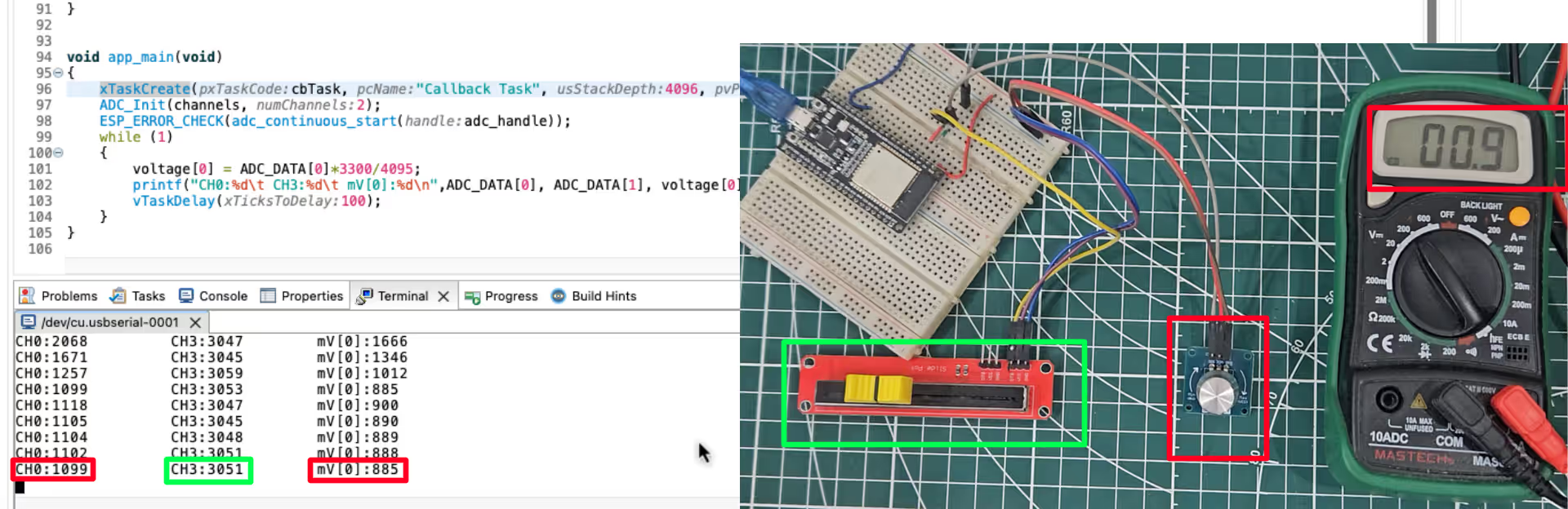
The Green boxes indicates the measurement for ADC_CHANNEL_3. The sliding potentiometer is connected to this channel. You can see the Raw and voltage data for this channel is printed on the console.
The Red boxes indicates the measurement for the ADC_CHANNEL_0. The rotary potentiometer is connected to this channel. The voltmeter is also connected to the potentiometer output. You can see the printed voltage value is approximately same as the one measured by the voltmeter.
This means that the ADC peripheral of the ESP32 can measure the input analog voltage to some degree of accuracy. We are getting the data from both the channels as well.

Thank you! This has helped me immensely with ADC continuous mode – very clear!
Thanks for this! I’ve been trying to figure out the esp-idf v5 ADC read with little success. You are a legend!