Learn how to read and write data to the MPU6050 accelerometer via I2C on ESP32 using ESP‑IDF. The tutorial includes wiring, configuration, master init & read/write ID of the device. The project is available to download at the end of the post.

This is the 4th tutorial in the ESP32 series using the espressif-IDF and 2nd in a mini series covering SPI peripheral of ESP32. In today’s tutorial we will read and write the data to the slave device.
Today we will connect an accelerometer (MPU6050) via the I2C. In order to get the acceleration data from this sensor, the ESP32 need to perform both Read and Write operations to the device memory. Hence we will be able to cover the following in today’s tutorial:
- How to write the data at a specific memory location in the slave device.
- How to read the data from a specific memory location in the slave device.
Note that this tutorial does not cover the full functionality of the MPU6050. We are just focussing on Writing and Reading data from the sensor using the ESP32. Here we will do the minimum configuration and read the acceleration data from the sensor.
VIDEO TUTORIAL
You can check the video to see the complete explanation and working of this project.
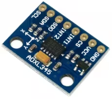
Introducing MPU6050
The MPU6050 is a popular 6-axis motion tracking device that combines a 3-axis gyroscope and a 3-axis accelerometer in a single chip. It communicates via the I2C protocol and is widely used in robotics, drones, gesture-based applications, and wearable devices for motion detection and orientation tracking.
Some of its important features are:
- Combines 3-axis gyroscope and 3-axis accelerometer
- I2C interface for easy microcontroller communication
- Built-in Digital Motion Processor (DMP) for sensor fusion
- Operates at low power with 3.3V or 5V compatibility
WIRING DIAGRAM
Below is the image showing the connection between MPU6050 and the ESP32.
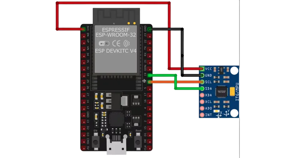
As you can see in the image above, the pin connection is as follows:
| Sensor Pin | ESP32 Connection | Description |
|---|---|---|
| SCL | GPIO 18 (I2C0_SCL) | Clock line for I2C communication |
| SDA | GPIO 19 (I2C0_SDA) | Data line for I2C communication |
| AD0 | Not Connected | Determines I2C address; used later for slave address configuration |
| VCC | 3.3V from ESP32 | Powers the MPU6050 sensor |
SLAVE ADDRESS OF MPU6050
Below is the image from pg 33 of the MPU6050 datasheet.
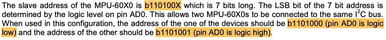
The 7 bit address is b110100X. Here the value of X depends on the pin AD0. We have left this pin un-connected and therefore this pin can be treated as Logic LOW. This means that the 7bit Slave Address of the device is 0x68. The ESP32 needs this 7bit address only. The I2C library will add the Read/Write bit by itself.
THE CODE
ESP32 I2C Configuration
#define I2C_NUM I2C_NUM_0
#define I2C_SCL GPIO_NUM_18
#define I2C_SDA GPIO_NUM_19
static esp_err_t i2c_master_init(void)
{
    int i2c_master_port = I2C_NUM;

    i2c_config_t conf = {
        .mode = I2C_MODE_MASTER,
        .sda_io_num = I2C_SDA,
        .scl_io_num = I2C_SCL,
        .sda_pullup_en = GPIO_PULLUP_ENABLE,
        .scl_pullup_en = GPIO_PULLUP_ENABLE,
        .master.clk_speed = 400000,
    };
    i2c_param_config(i2c_master_port, &conf);
    return i2c_driver_install(i2c_master_port, conf.mode, 0, 0, 0);
}The i2c_master_init function will be used to initialise the I2C in the master mode. Here we will first configure the I2C parameters, which are as follows
- mode sets the mode for the I2C. It can be either master/slave. Since we want the ESP32 to be a master, we will set the I2C_MODE_MASTER.
- sda_io_num sets the GPIO for the SDA(Data Pin). As shown in the connection diagram, the SDA is the GPIO_NUM_19.
- scl_io_num will set the GPIO for the SCL (Clock Pin). It is defined as GPIO_NUM_18.
- pullup_en basically configures if you want to enable the internal pullups for the SDA and SCL Pins. Since we are not using any external pullup resistors, we should enable the internal pullups.
- master.clk_speed configures the speed (in Hz) for the master. Most of the devices work at 100Khz, or 400Khz. The MPU6050 can work with 400Khz, so I have it to 400000.
i2c_param_config will configure the parameters we just set. I2C_NUM_0 is the I2C instance we are using. If your board have more than 1 I2C, then you should define the instance as per the pins you are using.
After configuring the parameters, i2c_driver_install will install the driver. The parameters are
- i2c_port_t, the I2C instance, which is 0 in our case.
- i2c_mode_t mode, the I2C mode, which is master in this case.
- slv_rx_buf_len and slv_tx_buf_len, The size of the RX and TX buffers. The buffers are only needed if the ESP32 is being used in the slave mode. Since we are using it as a master, we will keep these buffers as 0.
- intr_alloc_flags is to set the interrupt flag for the I2C. We will keep it as 0 too, since we are not using any interrupts.
Read and Write Functions
Now we will write the functions to Read and Write the data to the device. Mostly all the I2C devices has memory locations arranged in the form of Registers. These Registers serves specific purpose according to the device’s functionality. We will write the functions to read and write data into the MPU6050 Registers.
Reading data
Below is the function to read required number the data bytes, starting from a specific register in MPU6050.
esp_err_t mpuReadfromReg (uint8_t Reg, uint8_t *ReadBuffer, size_t len)
{
	return (i2c_master_write_read_device(I2C_NUM, MPU_ADDR, &Reg, 1, ReadBuffer, len, 2000));
}The parameters of this function are:
- @Reg is the address of the register, where we want to start reading the data from.
- @ReadBuffer is the pointer to the buffer, where we want to store the data read.
- @len is the number of bytes we want to read, starting from the address Reg.
The function i2c_master_write_read_device is used from the ESP32 I2C library. This function is used to first write the data to the slave device and then read the data from it.
It is basically used in the situation where we want to read the data from a specific memory location inside the slave device. In such situation, we first need to send the Address of the memory location, where we want to read the data from, and then perform the reading operation. The parameters of this function are as follows:
- @i2c_num I2C port number to perform the transfer on. I2C_NUM_0 in our case.
- @device_address I2C device’s 7-bit address. 0x68 in this case.
- @write_buffer Bytes to send on the bus. We want to read from the address Reg, so we will send it.
- @write_size Size, in bytes, of the write buffer. The Registers in MPU6050 are 1 byte in size, therefore send 1.
- @read_buffer Buffer to store the bytes received on the bus. ReadBuffer in this case.
- @read_size Size, in bytes, of the read buffer. len in this case.
- @ticks_to_wait Maximum ticks to wait before issuing a timeout. 2 seconds in this case.
Writing Data
Below is the function to write a single data byte at a specific memory location inside the slave device.
esp_err_t mpuWriteReg (uint8_t Reg, uint8_t data)
{
	uint8_t writeBuf[2];  // writeBuf[len+1];
	writeBuf[0] = Reg;
	writeBuf[1] = data;
	return (i2c_master_write_to_device(I2C_NUM, MPU_ADDR, writeBuf, 2, 1000));
}The function mpuWriteReg will write a single data byte to the memory Address (Reg).
Inside it we will call the function i2c_master_write_to_device, which is used to send the required number of data bytes to the device. Since we have 2 bytes to write, Register Address and the data byte, we will first define a buffer to store these 2 bytes. The Reg address needs to be sent first, hence store it in the first element of the buffer.
The main function
Inside the main function we will first initialise the I2C. If the initialisation is successful, log the message on the console.
void app_main(void)
{
    uint8_t data[10];
    ESP_ERROR_CHECK(i2c_master_init());
ESP_LOGI(TAG, "I2C initialized successfully");Initialising the sensor
In order to initialise the sensor, we will first check if the sensor is responding by reading the “WHO_AM_I (0x75)” Register. If the sensor responds with 0x68, that would means it’s available and good to go.
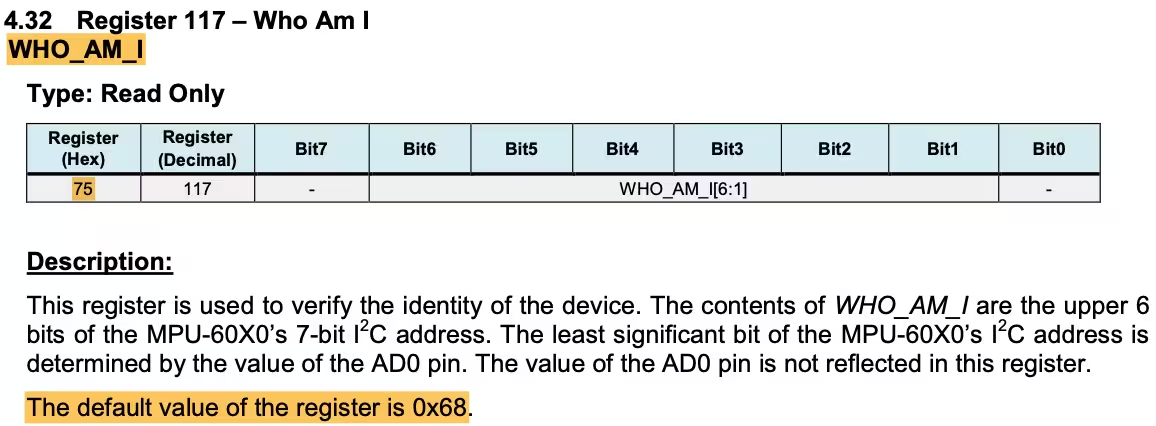
    mpuReadfromReg(0x75, data, 1);
ESP_LOGI(TAG, "%X", data[0]);Here we will use the function mpuReadfromReg to directly read from the given memory register (0x75). If the sensor respond with the value 0x68, we can proceed with the rest of the initialisation.
Then we will configure the “PWR_MGMT_1 (0x6B)” Register. Below is the image of the register.
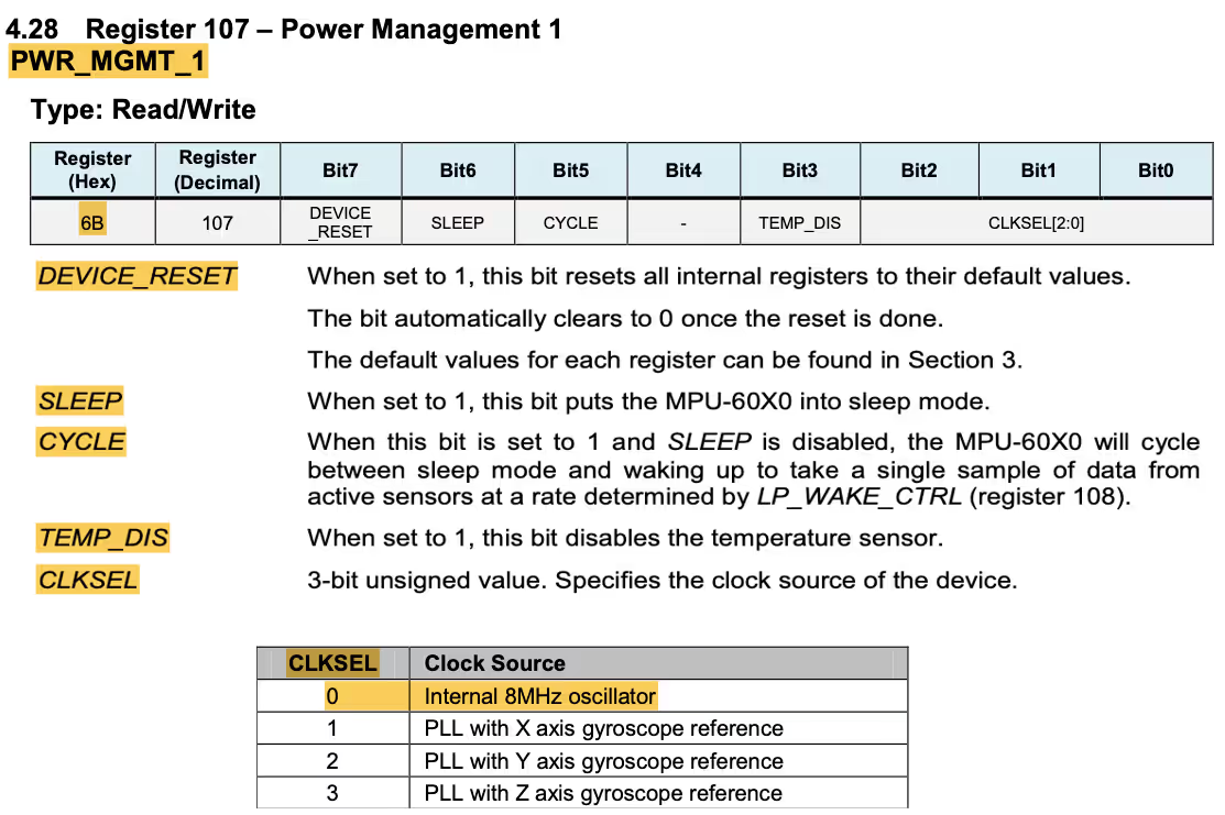
mpuWriteReg(0x6B, 0);We will reset this register to 0. In doing so, we will :
- Select the internal clock source of 8 MHz.
- The Temperature sensor will be enabled.
- The CYCLE between sleep mode and wakeup will be enabled.
- The SLEEP mode will be disabled.
- Also we are not performing the RESET.
Next we have to set the Data output Rate or Sample Rate. This can be done by writing into “SMPLRT_DIV (0x19)” Register. This register specifies the divider from the gyroscope output rate used to generate the Sample Rate for the MPU6050.
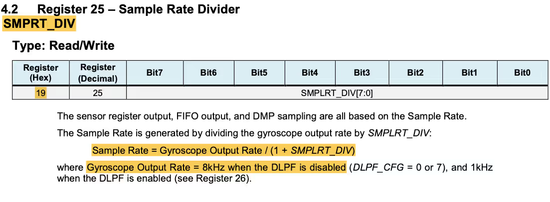
As the formula says Sample Rate = Gyroscope Output Rate / (1 + SMPLRT_DIV). We will keep the DLPF disabled, so the Gyroscope Output Rate will remain 8KHz. To get the sample rate of 1KHz, we will set the SMPLRT_DIV value to 7.
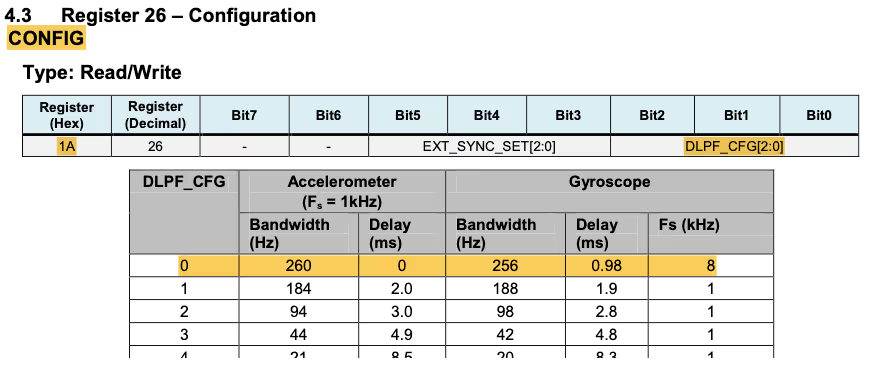
mpuWriteReg(0x19, 7); // sample rate 1KHzThe “CONFIG (0x1A)” Register can be used to configure the DLPF. Since this register is reset to 0 by default, the DLPF is disabled and the gyroscope output rate is set to 8KHz.
Now we will configure the Accelerometer register by modifying the “ACCEL_CONFIG (0x1C)”Registers.
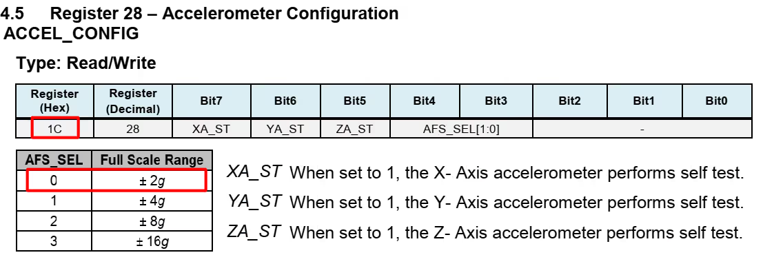
mpuWriteReg(0x1C, 0); // ACC FS Range ±2gWriting (0x00) to this register would set the Full scale range of ± 2g in ACCEL_CONFIG with self test disabled.
Read Values from MPU6050
In the while loop, we will Read the Data from the sensor and convert it in the ‘g’ format.
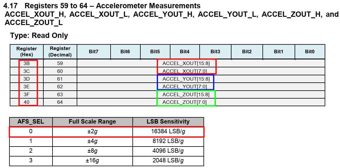
We can read 1 BYTE from each Register separately or just read all 6 BYTES in a burst, all together starting from ACCEL_XOUT_H(0x3B) Register.
    while (1)
    {
mpuReadfromReg(0x3B, data, 6);Here we are reading 6 bytes of data, starting from 0x3B register. These values will be stored in the data buffer.
The ACCEL_XOUT_H (0x3B) Register stores the higher Byte for the acceleration data along X-Axis and Lower Byte is stored in ACCEL_XOUT_L Register. So we need to combine these 2 BYTES into a 16 bit integer value. Below is the process to do that:-
ACCEL_X = (ACCEL_XOUT_H <<8) | ACCEL_XOUT_L
We are shifting the higher 8 bits to the left and than adding the result with the lower 8 bits.
Similarly we can do the same for the ACCEL_YOUT and ACCEL_ZOUT Registers.
		int16_t RAWX = (data[0]<<8)|data[1];
		int16_t RAWY = (data[2]<<8)|data[3];
int16_t RAWZ = (data[4]<<8)|data[5];These values are still the RAW values and we need to convert them into proper ‘g’ format. You can see in the picture above that for the Full-Scale range of ± 2g, the sensitivity is 16384 LSB/g. So to get the ‘g‘ value, we need to divide the RAW from 16384.
		float xg = (float)RAWX/16384;
		float yg = (float)RAWY/16384;
float zg = (float)RAWZ/16384;We will use the function sprintf to covert the float values to the character format and LOG them into the console. Also give a delay of 1 second between the readings.
		ESP_LOGI(TAG, "\nx=%.2f\ty=%.2f\tz=%.2f", xg, yg, zg);
		sleep(1);
	}
}RESULT
Below is the image showing the console LOG for one of the positions of the sensor.
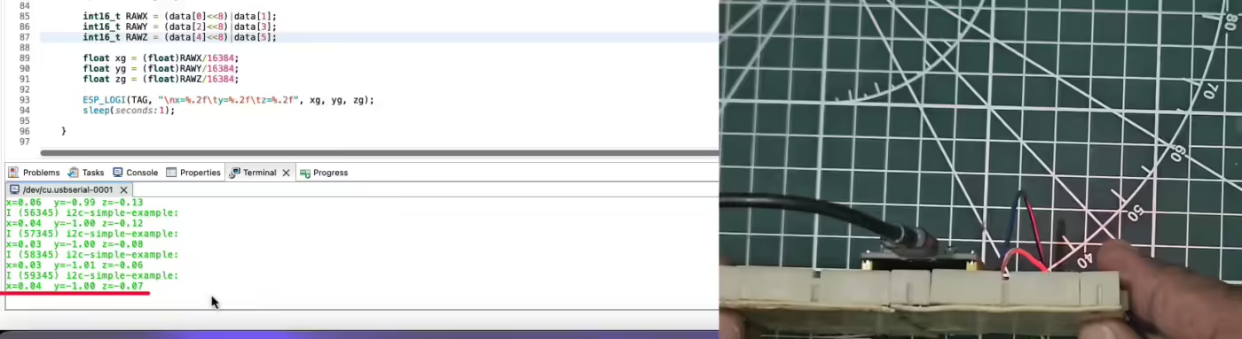
As you can see, the Acceleration in the x-axis = 0.04g, y-axis = -1g and in the z-axis = -0.07g. These are the acceleration values when the sensor is tilted in a certain position.
You can check out the video below to see the complete result.
PROJECT DOWNLOAD


I love your tourial about esp-idf. Please make more. Thanks!
Sure I will make more. I am busy with something now a days, so I will probably start making them in a month or 2.