Published: November 6, 2025
Last Updated: February 6, 2026
Last Updated: February 6, 2026
Interface SH1106 I2C 1.3” OLED Display with Arduino – Full Guide with Bitmaps and Animations
The SH1106 OLED display is a popular 1.3-inch graphical screen often used in small embedded projects. It looks very similar to the SSD1306 OLED, but it runs on a slightly different driver chip. In this tutorial, we’ll learn how to interface the SH1106 OLED display with Arduino using the I2C communication protocol.
We’ll start with the basics—understanding the pinout and connections—and then move on to displaying text, shapes, and images. Later in the post, we’ll also explore how to create custom bitmaps and even add simple animations to make your project more interactive.
If you are new to OLED displays, I recommend checking out my detailed guide on the Arduino SSD1306 OLED Display Tutorial before continuing. It explains the fundamentals that will help you better understand how OLEDs work and how to use them effectively in your Arduino projects.
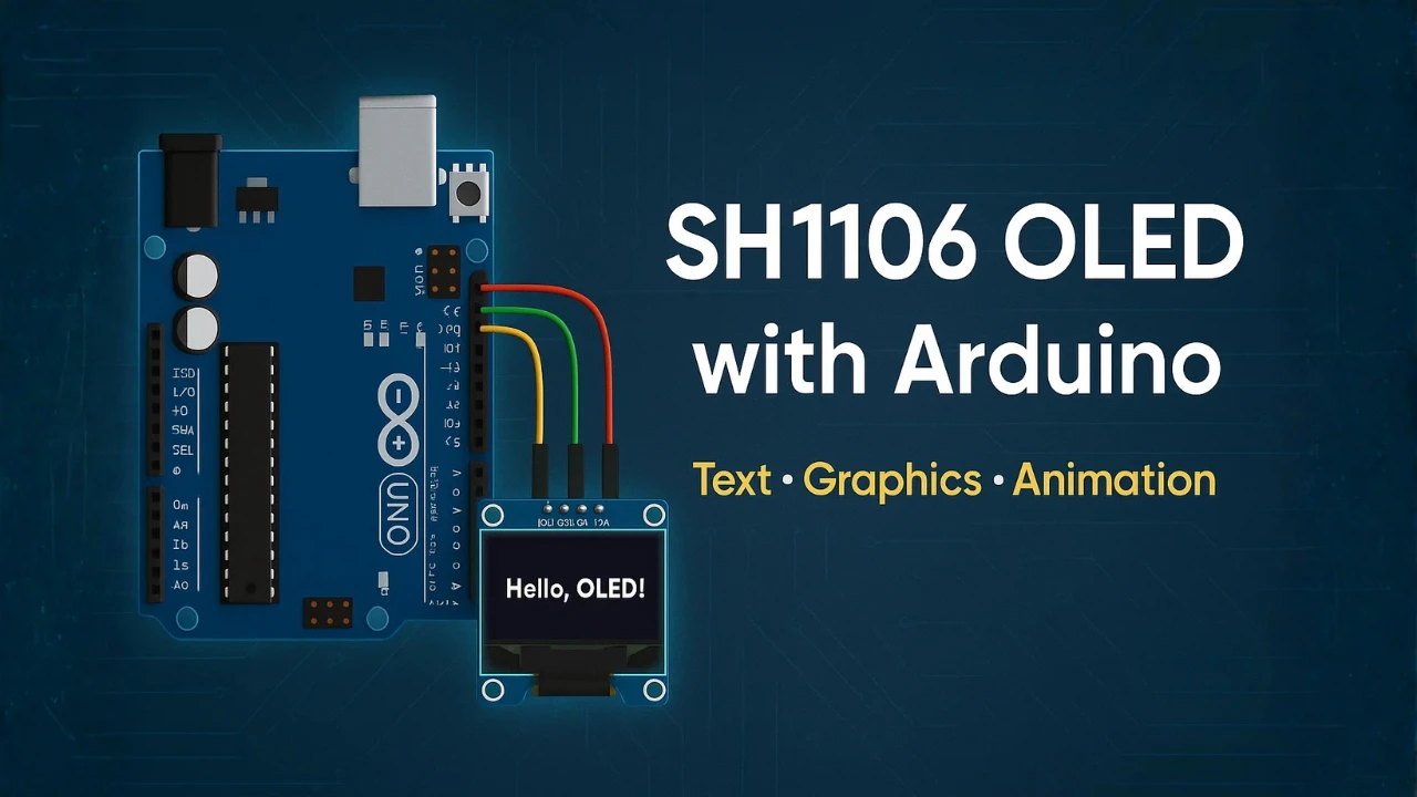
Table Of Contents
- Introduction to SH1106 OLED Display
- SH1106 Circuit Diagram and Wiring
- Installing SH1106 Library for Arduino
- Displaying Text and Graphics on SH1106 OLED
- Displaying Numbers and Floating Values
- Creating and Displaying Bitmap Images
- Adding Animations on SH1106 OLED
- How to Create Your Own Animations
- Common Issues and Troubleshooting
- Conclusion
Introduction to SH1106 OLED Display
The SH1106 OLED display is a compact 1.3-inch screen that uses I2C communication to connect with microcontrollers like Arduino, ESP32, and STM32. It’s a monochrome display, meaning it can show graphics and text in a single color, usually white, blue, or yellow, depending on the module version.
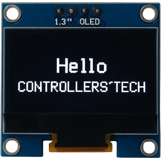
This display has a resolution of 128×64 pixels, offering a crisp and clear output that’s perfect for showing sensor data, menus, or small graphical animations. Its low power consumption and high contrast make it ideal for battery-powered projects and IoT devices.
Difference between SH1106 and SSD1306 Displays
The SH1106 and SSD1306 displays look almost identical from the outside, but they differ internally in their driver IC and memory organization.
- The SSD1306 controller has a built-in 128×64 memory that directly matches the display’s pixel resolution.
- The SH1106, however, has 132×64 internal memory, meaning there are 4 extra columns of pixels that aren’t visible on the display.
Because of this small difference, SSD1306 libraries may not work perfectly with SH1106 modules. You might notice text shifting or graphics misalignment if you use the wrong library. That’s why it’s important to use a library specifically designed for the SH1106 controller.
Why Use SH1106 with Arduino
The SH1106 OLED offers a slightly larger display area (1.3″) compared to the 0.96″ SSD1306, making it easier to read data and display graphics. It’s also widely available, inexpensive, and easy to interface using just two wires (SDA and SCL) via the I2C protocol.
Another reason to choose the SH1106 is its excellent contrast and sharpness, even under different lighting conditions. It doesn’t require a backlight like LCDs, which saves power and simplifies wiring.
With Arduino’s wide library support and straightforward coding environment, you can easily display text, sensor readings, custom logos, and animations on the SH1106 screen within minutes.
Required Hardware and Connections
To get started with this project, you’ll need a few basic components:
- Arduino Board – You can use Uno, Nano, or Mega.
- 1.3″ SH1106 OLED Display (I2C version)
- Jumper Wires – For connecting the display to Arduino.
- Breadboard – Optional, for neat prototyping.
The I2C version of SH1106 has four pins:
- GND – Connect to Arduino GND
- VCC – Connect to 5V (or 3.3V for some modules)
- SCL – Connect to Arduino A5 (on Uno/Nano)
- SDA – Connect to Arduino A4 (on Uno/Nano)
Once these connections are made, your display will be ready for programming. In the next section, we’ll set up the required libraries and write code to initialize the display.
SH1106 Circuit Diagram and Wiring
Before we start coding, let’s take a look at how to connect the SH1106 OLED display with the Arduino board. The SH1106 uses the I2C communication protocol, which makes wiring very simple, only four pins are needed: VCC, GND, SDA, and SCL.
This section will explain the pinout of the SH1106 display, how to wire it correctly with Arduino, and how to verify that the connections are working properly.
SH1106 Pinout and I2C Connection
The SH1106 I2C OLED module usually comes with four pins. The image below shows the pinout of SH1106 I2C Oled display.
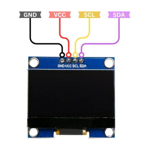
Here’s what each pin on the display does:
| Pin | Description | Connection to Arduino |
|---|---|---|
| GND | Ground | Connect to Arduino GND |
| VCC | Power Supply (3.3V or 5V) | Connect to 5V on Arduino Uno/Nano |
| SCL | Serial Clock Line | Connect to A5 on Arduino Uno/Nano (SCL pin) |
| SDA | Serial Data Line | Connect to A4 on Arduino Uno/Nano (SDA pin) |
Note: Some SH1106 modules work only at 3.3V, while others can handle 5V. Check your display’s datasheet or product label before connecting it to avoid damage.
The I2C communication allows multiple devices to share the same two data lines (SDA and SCL). Each device is identified by a unique I2C address — for SH1106, this is usually 0x3C or 0x3D, depending on the module version.
SH1106 Arduino Wiring
Let’s take the Arduino Uno as an example. You can connect the SH1106 display as follows:
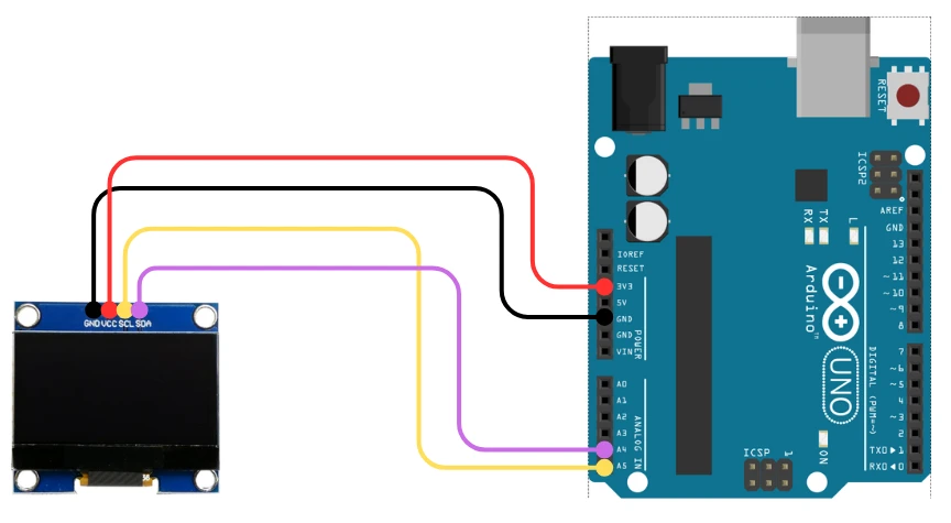
Here’s how to connect it:
| OLED Pin | Connects To | Description |
|---|---|---|
| VCC | 3.3V | Power supply for the display |
| GND | GND | Common ground |
| SDA | A4 (on Arduino Uno/Nano) | I2C Data line |
| SCL | A5 (on Arduino Uno/Nano) | I2C Clock line |
If you are using a different Arduino board, here are the equivalent I2C pins:
| Board | SDA Pin | SCL Pin |
|---|---|---|
| Arduino Uno/Nano | A4 | A5 |
| Arduino Mega | 20 | 21 |
| Arduino Leonardo | 2 | 3 |
| Arduino Due | 20 | 21 |
| ESP32 | GPIO 21 | GPIO 22 |
Make sure the connections are firm and not reversed. Incorrect wiring may cause the display not to power up or communicate with Arduino.
Testing the Connections
Once the wiring is complete, it’s time to verify the I2C connection. To do this, we can use the I2C Scanner sketch shown below.
#include <Wire.h>

void setup() {
  Wire.begin();
  Serial.begin(9600);
  Serial.println("Scanning for I2C devices...");
  for (byte i = 1; i < 127; i++) {
    Wire.beginTransmission(i);
    if (Wire.endTransmission() == 0) {
      Serial.print("I2C device found at address 0x");
      Serial.println(i, HEX);
    }
  }
}

void loop() {}Upload this code to your Arduino and open the Serial Monitor. You’ll see the detected I2C address printed there.
The image below shows the result of the I2C scanner code.
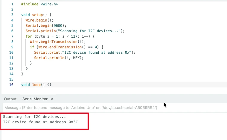
This means the SH1106 display is successfully detected. If no device is found, double-check your wiring, power, and SDA/SCL connections.
Once your display responds at address 0x3C, you are ready to move on to the next step — installing the SH1106 library and writing your first code to initialize and display text on the screen.
Installing SH1106 Library for Arduino
To control the SH1106 OLED display using Arduino, we need to install a suitable library that supports this controller. The SH1106 is very similar to the SSD1306, so it also works with the Adafruit GFX graphics library, but it requires its own display driver library for proper pixel mapping.
In this section, we’ll install the required libraries, understand how they work together, and test a simple example to initialize the display.
Using the Adafruit GFX and SH1106 Library
To make the SH1106 OLED work properly, we’ll use two main libraries:
- Adafruit GFX Library – This library provides basic graphics functions like drawing lines, circles, and displaying text. It acts as a universal graphics engine for many displays.
- Adafruit SH110X Library – This library specifically supports the SH1106 and SH1107 OLED driver chips. It handles the communication between Arduino and the SH1106 controller through I2C or SPI.
Together, these libraries make it easy to draw shapes, text, and even custom images on the OLED screen with very few lines of code.
If you have previously worked with the SSD1306 display, this setup will look very familiar. The only difference is that we are using the Adafruit_SH110X library instead of Adafruit_SSD1306.
How to Install Libraries in Arduino IDE
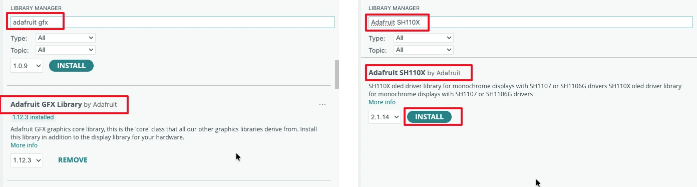
You can install both libraries directly from the Arduino Library Manager. Follow these steps:
- Open Arduino IDE.
- Go to Sketch → Include Library → Manage Libraries…
- In the search box, type “Adafruit GFX” and install the Adafruit GFX Library.
- Next, search for “Adafruit SH110X” and install the Adafruit SH110X Library.
Once installed, Arduino will automatically link these libraries in your sketches. You’ll now have access to functions like display.display(), display.clearDisplay(), and text/graphics drawing routines.
If you prefer manual installation, you can also download both libraries as ZIP files from the Adafruit GitHub repositories and add them using Sketch → Include Library → Add .ZIP Library…
Basic Example Code to Initialize Display
After installing the libraries, let’s test if the SH1106 display initializes correctly. Open a new Arduino sketch and paste the following code:
#include <Wire.h>
#include <Adafruit_GFX.h>
#include <Adafruit_SH110X.h>

#define SCREEN_WIDTH 128
#define SCREEN_HEIGHT 64
#define OLED_RESET -1 // Reset pin not used with I2C

Adafruit_SH1106G display(SCREEN_WIDTH, SCREEN_HEIGHT, &Wire, OLED_RESET);

void setup() {
  Serial.begin(9600);
  Serial.println("SH1106 OLED Test");

  if(!display.begin(0x3C, true)) { // Address 0x3C for most modules
    Serial.println("SH1106 allocation failed");
    for(;;);
  }

  display.display(); // Push buffer to the screen
}

void loop() {
}Explanation of the code:
- Includes required libraries for I²C and OLED display (
Wire,Adafruit_GFX,Adafruit_SH110X). - Defines screen width, height, and OLED reset pin (not used with I²C).
- Creates a display object for the SH1106 OLED module.
- In
setup():- Initializes serial communication.
- Initializes the OLED display at I²C address
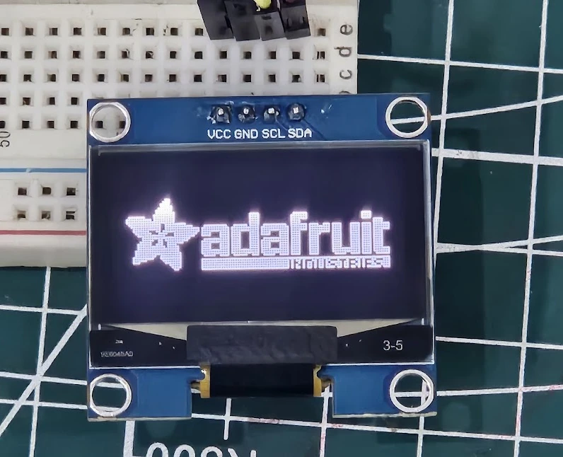
0x3C. - Displays the initial buffer (usually the Adafruit logo).
- The
loop()function is empty (no continuous updates).
After uploading the code, the Adafruit logo will appear on the screen. This is shown in the image below.
Displaying Text and Graphics on SH1106 OLED
Once the SH1106 OLED display is properly initialized, you can start displaying text and graphics on it. The Adafruit GFX library provides a powerful yet simple way to draw shapes, print text, and control screen effects.
In this section, we’ll go step by step — from showing simple text to drawing geometric shapes like lines, rectangles, and circles. We’ll also learn how to adjust display contrast and enable text scrolling for better visual effects.
Displaying Simple Text
Displaying text on the SH1106 OLED is straightforward. The GFX library lets you choose text size, color, and cursor position. Here’s a simple example:
#include <Wire.h>
#include <Adafruit_GFX.h>
#include <Adafruit_SH110X.h>
#define SCREEN_WIDTH 128
#define SCREEN_HEIGHT 64
#define OLED_RESET -1 // Reset pin not used with I2C
Adafruit_SH1106G display(SCREEN_WIDTH, SCREEN_HEIGHT, &Wire, OLED_RESET);
void setup() {
Serial.begin(9600);
Serial.println("SH1106 OLED Test");
if(!display.begin(0x3C, true)) { // Address 0x3C for most modules
Serial.println("SH1106 allocation failed");
for(;;);
}
display.clearDisplay();
display.setTextSize(2);
display.setTextColor(SH110X_WHITE);
display.setCursor(0, 10);
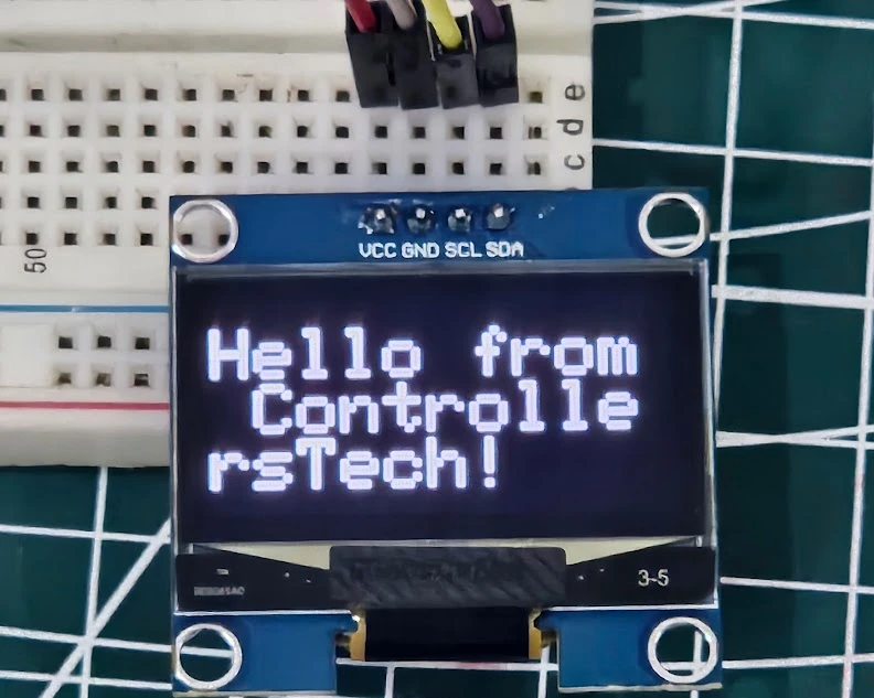
display.println("Hello from ControllersTech!");
display.display();
}
void loop() {
}Explanation of the Code
- The code starts by including the required libraries for I2C and SH1106.
- We define the display resolution as 128×64 pixels, matching the module’s size.
- The
display.begin(0x3C, true)function initializes the OLED at address 0x3C. - Inside
setup(), we clear the display, set the text size and color, and print a sample message. - Finally,
display.display()updates the screen with the written content.
The image below shows the text “Hello from ControllersTech!” displaying on the OLED screen.
In the next section, we’ll explore how to display text, draw shapes, and add basic graphics to the screen.
You can print multiple lines by moving the cursor position and calling println() again.
Drawing Lines, Rectangles, and Circles
The Adafruit GFX library also provides easy functions to draw basic shapes — useful for creating UI elements, progress bars, or custom icons.
Here’s a sample code showing different shapes:
#include <Wire.h>
#include <Adafruit_GFX.h>
#include <Adafruit_SH110X.h>

#define SCREEN_WIDTH 128
#define SCREEN_HEIGHT 64
#define OLED_RESET -1

Adafruit_SH1106G display(SCREEN_WIDTH, SCREEN_HEIGHT, &Wire, OLED_RESET);

void setup() {
  display.begin(0x3C, true);
  display.clearDisplay();

  // Draw a line
  display.drawLine(0, 0, 127, 63, SH110X_WHITE);

  // Draw rectangle outline
  display.drawRect(10, 10, 50, 30, SH110X_WHITE);

  // Draw filled rectangle
  display.fillRect(70, 10, 40, 20, SH110X_WHITE);

  // Draw circle outline
  display.drawCircle(30, 50, 10, SH110X_WHITE);

  // Draw filled circle
  display.fillCircle(90, 50, 10, SH110X_WHITE);

  display.display();
}

void loop() {
}Explanation of the code:
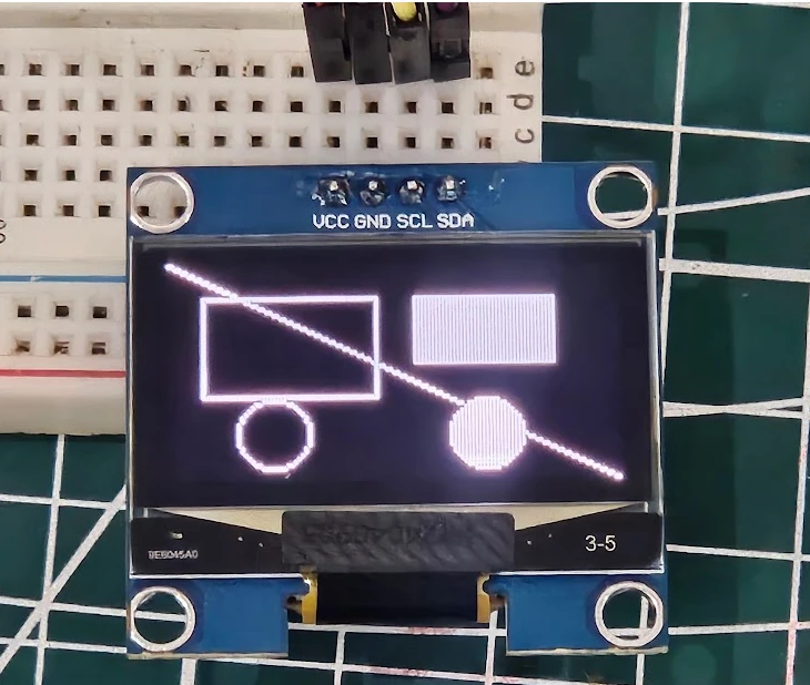
drawLine(x0, y0, x1, y1, color)draws a straight line between two points.drawRect(x, y, w, h, color)andfillRect()create empty or filled rectangles.drawCircle(x, y, r, color)andfillCircle()create circular shapes.
These commands make it easy to design custom layouts, highlight areas, or create animated graphics. The image below shows the output on the screen for the above code.
Displaying Numbers and Floating Values
Printing numbers on the SH1106 OLED display is just as easy as printing text. Whether you want to show sensor readings, counter values, or real-time measurements, the Adafruit GFX library provides simple methods to print both integers and floating-point numbers. You can even combine them with text for clear and informative displays.
Displaying Integer Values
To display integer values, you can directly use the display.print() or display.println() functions — just like you would use with the Serial Monitor.
Here’s a simple example that shows a counter increasing every second:
#include <Wire.h>
#include <Adafruit_GFX.h>
#include <Adafruit_SH110X.h>

#define SCREEN_WIDTH 128
#define SCREEN_HEIGHT 64
#define OLED_RESET -1

Adafruit_SH1106G display(SCREEN_WIDTH, SCREEN_HEIGHT, &Wire, OLED_RESET);

int counter = 0;

void setup() {
  display.begin(0x3C, true);
  display.clearDisplay();
  display.setTextSize(2);
  display.setTextColor(SH110X_WHITE);
}

void loop() {
  display.clearDisplay();
  display.setCursor(10, 20);
  display.print("Count: ");
  display.print(counter);
  display.display();
  counter++;
  delay(1000);
}In this example:
- The variable
counterincreases by 1 every second. display.print(counter);shows the current count value.- Each time the display is updated, it clears the previous value to prevent overlapping text.
Tip: If you forget to use display.clearDisplay(), the old numbers might overlap with the new ones, making the display unreadable.
The gif below shows the output of the code.

Printing Floating Point Numbers with Precision
The Adafruit GFX library also allows you to display floating-point numbers directly using display.print(). You can control the number of decimal places by passing a second parameter to the print() function.
Example:
#include <Wire.h>
#include <Adafruit_GFX.h>
#include <Adafruit_SH110X.h>
#define SCREEN_WIDTH 128
#define SCREEN_HEIGHT 64
#define OLED_RESET -1
Adafruit_SH1106G display(SCREEN_WIDTH, SCREEN_HEIGHT, &Wire, OLED_RESET);
float temperature = 23.2678;
void setup() {
display.begin(0x3C, true);
display.clearDisplay();
display.setTextSize(1);
display.setTextColor(SH110X_WHITE);
display.setCursor(10, 20);
display.print("Temp: ");
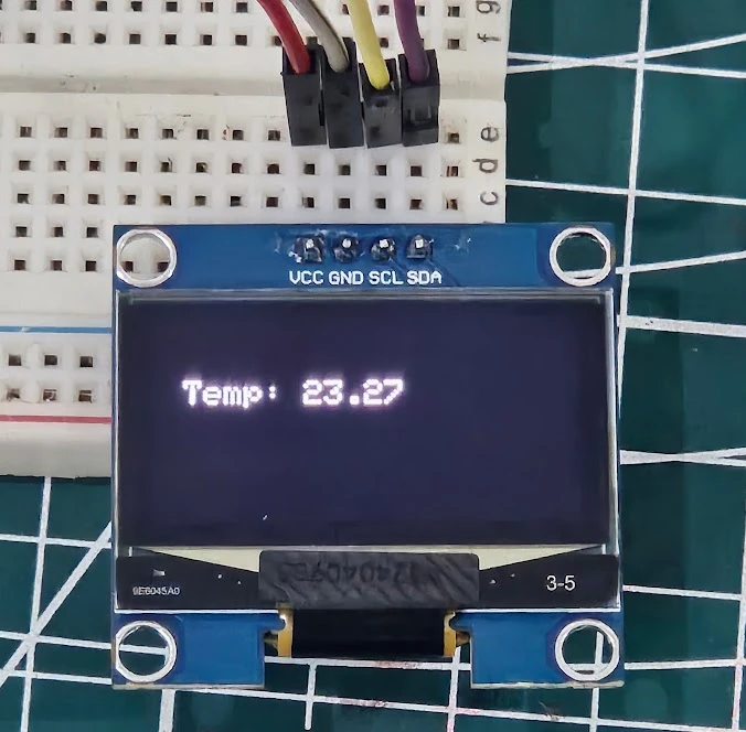
display.print(temperature, 2); // prints 23.27
display.display();
}
void loop() {
}In the line display.print(temperature, 2);, the number 2 specifies that only two digits after the decimal point should be shown.
You can adjust this value depending on the precision you need — for example, use (temperature, 1) for one decimal place or (temperature, 3) for three.
This feature is very helpful for displaying sensor values such as temperature, voltage, or humidity, where accurate decimal representation is needed.
Note: Avoid using too many decimal places because the OLED has limited space and smaller fonts may become hard to read.
The image below shows the float number displaying on the Oled.
Creating and Displaying Bitmap Images
The SH1106 OLED display is not limited to just text and shapes — you can also display custom images, icons, and logos by converting them into bitmap format. This feature is perfect for adding branding, startup logos, or small graphical elements to your Arduino projects.
In this section, we’ll learn how to convert an image into a compatible bitmap format, generate the C array code, and display it on the SH1106 OLED using Arduino.
Understanding Bitmaps on OLED Displays
A bitmap is a collection of binary data that represents each pixel on the screen.
- Each bit in the array corresponds to one pixel.
- A value of 1 means the pixel is turned ON (white), while 0 means it’s OFF (black).
- Since the SH1106 display is monochrome, there are no shades or colors — only black and white pixels.
You can use bitmaps to display small icons (like a Wi-Fi or battery symbol) or full-screen logos for branding your project.
Example of a simple 8×8 pixel bitmap:
const unsigned char myLogo [] PROGMEM = {
  0x00, 0x7E, 0x81, 0xA5, 0x81, 0x7E, 0x00,
  // more hex values...
};Here, each byte represents 8 pixels, and the pattern defines the shape to be displayed.
Converting Images to Bitmaps
To use your own image, you need to convert it into a C byte array. You can easily do this using the Image2CPP online tool.
The image below shows how to create bitmap using an existing image.
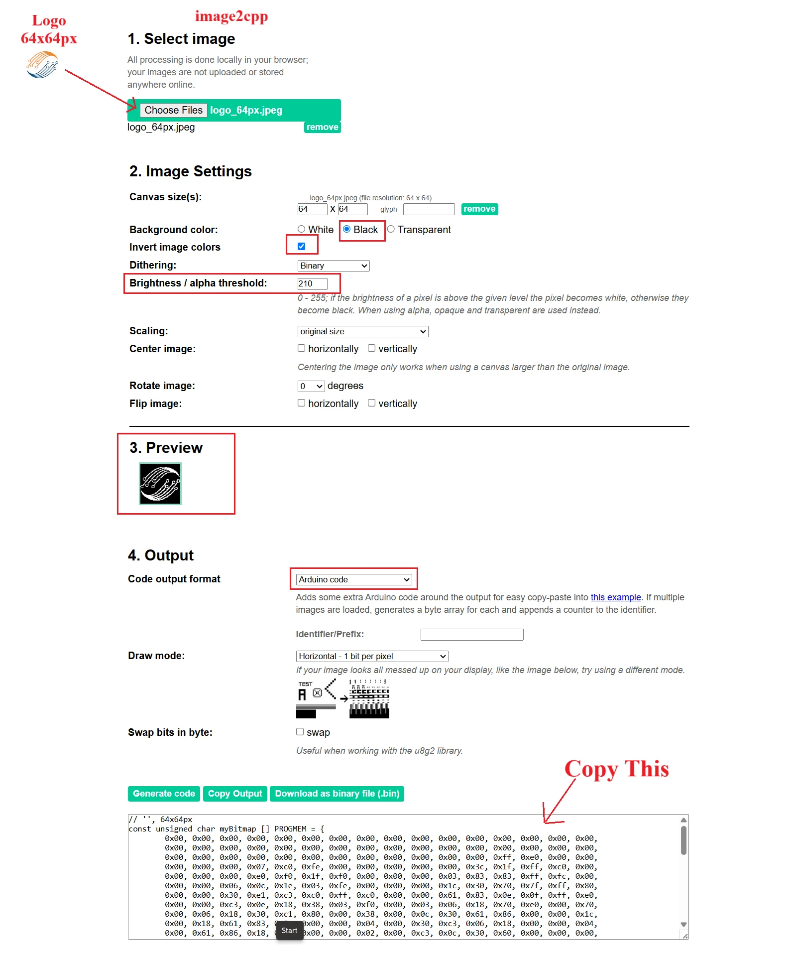
Follow these steps:
- Create a simple black-and-white image (for example, your logo).
- Upload it in Image2CPP.
- Configure the Image Settings. You can check the preview to see how the final image will look.
- Adjust the brightness/alpha threshold to generate clear image.
- Set output as Arduino Code.
- Choose Monochrome and Horizontal byte orientation.
- Click Generate Code and copy the byte array.
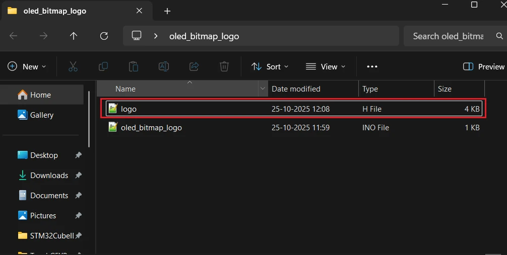
After copying the byte array, paste it in a new header file. It will keep the code clean as our image data will be in a separate file. In the image below, I have created a separate file named logo.h.

Now copy the file to the Arduino project folder, so that we can use it in the code.
Displaying a Bitmap Using Adafruit Library
To show your bitmap on the OLED, include the bitmap header file in the main file. Then use the drawBitmap() function provided by the Adafruit GFX library.
Here’s a simple example:
#include <Wire.h>
#include <Adafruit_GFX.h>
#include <Adafruit_SH110X.h>

#define SCREEN_WIDTH 128
#define SCREEN_HEIGHT 64
#define OLED_RESET -1

Adafruit_SH1106G display(SCREEN_WIDTH, SCREEN_HEIGHT, &Wire, OLED_RESET);

// Example bitmap data (replace with your own)
const unsigned char myLogo [] PROGMEM = {
  0x00, 0x7E, 0x81, 0xA5, 0x81, 0x7E, 0x00,
};

void setup() {
  display.begin(0x3C, true);
  display.clearDisplay();

  // Draw bitmap: (x, y, bitmapArray, width, height, color)
  display.drawBitmap(32, 0, myLogo, 64, 64, SH110X_WHITE);
  display.display();
}

void loop() {
}Explanation:
#include "logo.h"will include the bitmap header file.drawBitmap(x, y, array, width, height, color)is used to place the image on the screen.- You can adjust
(x, y)coordinates to move the image position. - Finally,
display.display()updates the screen to show the image.
If your image appears inverted (white background, black logo), simply invert the color setting in the online tool or change the color constant to SH110X_BLACK.
The image below shows the output of the above code. You can see the ControllersTech Logo is being displayed on the oled.
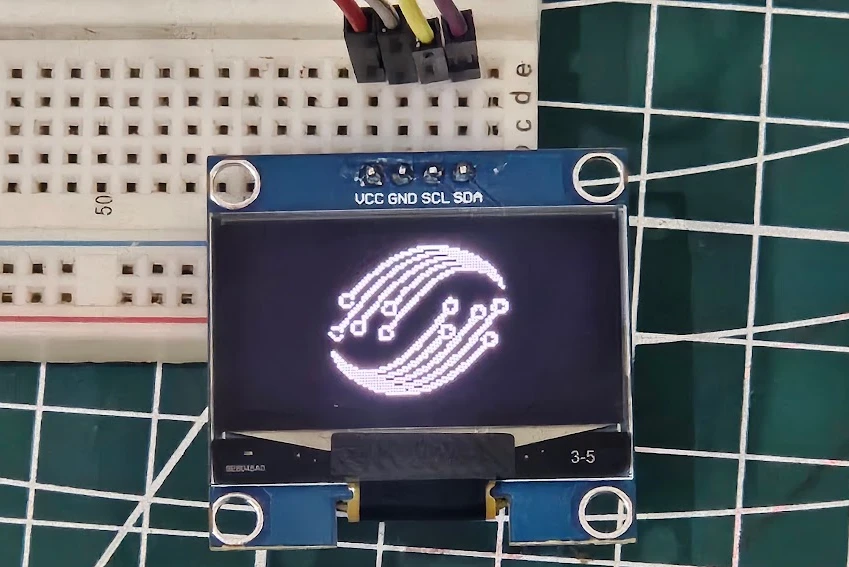
With this method, you can show your brand logo, custom icons, or even simple graphics at startup or during operation.
Combining Text and Bitmaps
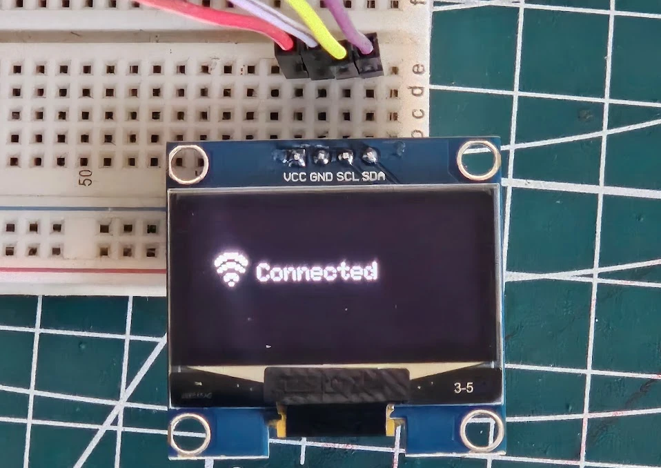
You can mix text and graphics to make your OLED display more interactive. For example, show a Wi-Fi icon beside connection status text, or a battery symbol next to voltage readings.
Example WiFi icon and Connected:
#include <Wire.h>
#include <Adafruit_GFX.h>
#include <Adafruit_SH110X.h>

#define SCREEN_WIDTH 128
#define SCREEN_HEIGHT 64
#define OLED_RESET -1

Adafruit_SH1106G display(SCREEN_WIDTH, SCREEN_HEIGHT, &Wire, OLED_RESET);

// 16x16 WiFi icon bitmap (simple example)
static const unsigned char PROGMEM wifi_icon[] = {
  0b00000000, 0b00000000,
  0b00000111, 0b11100000,
  0b00011111, 0b11111000,
  0b00111100, 0b00111100,
  0b01110000, 0b00001110,
  0b01100011, 0b11000110,
  0b00001111, 0b11110000,
  0b00011100, 0b00111000,
  0b00110000, 0b00001100,
  0b00000000, 0b00000000,
  0b00000011, 0b11000000,
  0b00000111, 0b11100000,
  0b00000110, 0b01100000,
  0b00000000, 0b00000000,
  0b00000001, 0b10000000,
  0b00000000, 0b00000000
};

void setup() {
  display.begin(0x3C, true);
  display.clearDisplay();

  // Draw WiFi icon at (10, 20)
  display.drawBitmap(10, 20, wifi_icon, 16, 16, SH110X_WHITE);

  // Draw text next to icon
  display.setTextSize(1);
  display.setTextColor(SH110X_WHITE);
  display.setCursor(30, 26);
  display.print("Connected");

  // Update display
  display.display();
}

void loop() {
}Here is how the code works:
- The bitmap array (
wifi_icon) defines a simple 16×16 WiFi symbol. display.drawBitmap(10, 20, wifi_icon, 16, 16, SH110X_WHITE);
→ Draws the icon at (x=10, y=20).- Then text
"Connected"is drawn right next to it using normal text functions. display.display();pushes everything to the OLED.
The image below shows the output of the code on the Oled.
Next, we’ll go one step further and learn how to create animations on the SH1106 OLED — by displaying multiple bitmaps in sequence for a smooth motion effect.
Adding Animations on SH1106 OLED
Animations can make your SH1106 OLED display come alive. You can create moving objects, blinking icons, or even scrolling graphics that add a professional touch to your Arduino projects. The concept is simple — by displaying a series of images one after another, you create the illusion of motion, much like a flipbook or video frame sequence.
In this section, we’ll understand how frame-based animation works, write a simple animation example, and finally create a moving logo on the OLED display.
Concept of Frame-Based Animation
The SH1106 OLED display doesn’t support video playback, but you can still show motion using frame-based animation. This method works by displaying different images (frames) quickly in succession.
Each frame is stored as a bitmap array in the Arduino sketch, and the code switches between these frames with short delays in between. When done correctly, this gives the appearance of smooth movement.
Here’s how it works conceptually:
- Prepare multiple bitmap frames of your image in slightly different positions.
- Display one frame on the OLED.
- Wait a short time (e.g., 100 milliseconds).
- Clear the screen and display the next frame.
- Repeat this process continuously.
Because the SH1106 OLED has a fast refresh rate, even simple frame-based motion looks fluid. You can animate text, icons, or objects moving across the screen.
Writing Code for Simple Animation
Let’s start with a very basic animation example — moving a small box across the display. This will help you understand the timing and update process.
#include <Wire.h>
#include <Adafruit_GFX.h>
#include <Adafruit_SH110X.h>

#define SCREEN_WIDTH 128
#define SCREEN_HEIGHT 64
#define OLED_RESET -1

Adafruit_SH1106G display(SCREEN_WIDTH, SCREEN_HEIGHT, &Wire, OLED_RESET);

void setup() {
  display.begin(0x3C, true);
  display.clearDisplay();
}

void loop() {
  for (int x = 0; x < 128; x += 2) { // Move the box across the screen
    display.clearDisplay();
    display.fillRect(x, 25, 20, 20, SH110X_WHITE); // Draw a 20x20 box
    display.display();
    delay(20); // Adjust for animation speed
  }
}Code Explanation:
- The loop moves a small square horizontally from left to right by incrementing the X position.
fillRect()draws the shape at each new position.clearDisplay()clears the previous frame to prevent overlapping graphics.- The
delay(20)value controls the animation speed — smaller values create smoother motion.
This simple approach works great for sliding icons, progress bars, or moving text.
The gif below shows the animation on the bitmap.

Pac-Man Animation on SH1106 OLED
This sketch creates a simple Pac-Man animation on an SH1106 OLED display. Pac-Man moves across the screen, chomping dots one by one and then resetting to repeat the sequence.
#include <Wire.h>
#include <Adafruit_GFX.h>
#include <Adafruit_SH110X.h>

#define SCREEN_WIDTH 128
#define SCREEN_HEIGHT 64
#define OLED_RESET -1
Adafruit_SH1106G display(SCREEN_WIDTH, SCREEN_HEIGHT, &Wire, OLED_RESET);

void drawPacman(int x, int y, bool mouthOpen) {
  int r = 12;  // Even bigger radius: 24x24 Pacman
  int cx = x + r;
  int cy = y + r;
  display.fillCircle(cx, cy, r, SH110X_WHITE);
  if (mouthOpen) {
    // Black triangle for open mouth facing right (scaled up further)
    display.fillTriangle(cx, cy, cx + r, cy - 6, cx + r, cy + 6, SH110X_BLACK);
  }
}

void drawDot(int x, int y) {
  // Slightly bigger dot: 6x6 filled square for visibility with huge Pacman
  display.fillRect(x, y, 6, 6, SH110X_WHITE);
}

void setup() {
  display.begin(0x3C, true);  // Use 0x3C for most SH1106G OLEDs; adjust if needed

  // Clear the entire screen during initialization
  display.clearDisplay();
  display.display();  // Force immediate clear to black

  // Initial big dots (6x6 squares, spaced wider for 24x24 Pacman)
  int dotY = 30;  // Moved up to center vertically now that WiFi is gone
  int dotPositions[5] = {12, 35, 58, 81, 104};
  for (int i = 0; i < 5; i++) {
    drawDot(dotPositions[i], dotY);
  }

  // Update display after all initial draws
  display.display();
}

void loop() {
  // Pacman animation: moves right, eats dots (erases them), chomps mouth, resets on screen cross
  static int pacX = -24;  // Start off-screen left (bigger size)
  static bool mouthOpen = true;
  static bool eaten[5] = {false};  // Match numDots
  static unsigned long lastUpdate = 0;
  const int pacY = 18;  // Pacman top-left Y (centered vertically)
  const int dotY = 30;  // Dots centered with Pacman
  int dotPositions[5] = {12, 35, 58, 81, 104};
  const int numDots = 5;
  const int moveSpeed = 4;  // Faster to traverse screen quicker with massive size
  const int animationDelay = 120;  // ms delay (balanced for big visual heft)

  unsigned long currentTime = millis();
  if (currentTime - lastUpdate >= animationDelay) {
    // Clear old Pacman position if on screen (bigger clear area)
    if (pacX >= 0 && pacX < SCREEN_WIDTH) {
      display.fillRect(pacX, pacY, 24, 24, SH110X_BLACK);  // Clear 24x24 area
    }

    // Move Pacman
    pacX += moveSpeed;
    bool shouldReset = (pacX > SCREEN_WIDTH);

    if (shouldReset) {
      // Reset animation: reposition Pacman and restore all dots
      pacX = -24;
      for (int i = 0; i < numDots; i++) {
        eaten[i] = false;
        drawDot(dotPositions[i], dotY);
      }
    } else {
      // Check for eating dots at new position (wider range for huge Pacman)
      for (int i = 0; i < numDots; i++) {
        if (!eaten[i] && abs((pacX + 12) - (dotPositions[i] + 3)) <= 12) {  // Center-to-center <=12
          eaten[i] = true;
          display.fillRect(dotPositions[i], dotY, 6, 6, SH110X_BLACK);  // Erase dot
        }
      }
    }

    // Draw new Pacman if on screen
    if (pacX >= 0) {
      drawPacman(pacX, pacY, mouthOpen);
      mouthOpen = !mouthOpen;  // Toggle for chomping
    }

    // Update display
    display.display();
    lastUpdate = currentTime;
  }
}How It Works (in short):
- Display setup:
Initializes the SH1106 OLED using the Adafruit library at I²C address0x3C. - Pac-Man drawing (
drawPacman):
Draws a filled circle for Pac-Man and a small black triangle to simulate an open mouth that toggles each frame. - Dot drawing (
drawDot):
Creates small white squares that act as the food pellets. - Setup phase:
Clears the display and draws 5 dots across the screen at fixed positions. - Loop animation:
- Pac-Man moves right by a few pixels every frame (
moveSpeed = 4). - His mouth opens and closes alternately (
mouthOpentoggles). - When he reaches a dot, the dot is erased to look like it’s eaten.
- After crossing the screen, Pac-Man resets to the left and dots reappear.
- Pac-Man moves right by a few pixels every frame (
- Display updates:
The screen buffer is updated usingdisplay.display()after each move.
Result:
The gif below shows the output of the code. A smooth Pac-Man chomp animation — Pac-Man moves from left to right, eats the dots, then restarts for a continuous looping effect.

How to Create Your Own Animations
Creating your own custom animations on the SSD1306 OLED display is one of the most exciting parts of using this module. You can design unique motion effects, such as moving icons, rotating logos, or sensor-based visualizations, by displaying a series of bitmap frames in quick succession.
In this section, we’ll go step by step through the process of designing, converting, and displaying your own animation frames on the OLED screen.
Converting Images to Bitmaps
To display any custom animation, you first need to convert your images into bitmap arrays that Arduino can understand. Since the SSD1306 is a monochrome display, all images must be black and white.
You can follow the process of converting image to Bitmap mentioned above. To simulate an animation, you need to convert multiple frames and save them different header files, for example, frame1.h, frame2.h, frame3.h etc.
Displaying Custom Frames in a Loop
Once you’ve converted your images, it’s time to display them in sequence to form an animation.
Here’s an example of how to loop through several bitmap frames:
#include <Wire.h>
#include <Adafruit_GFX.h>
#include <Adafruit_SH110X.h>

#define SCREEN_WIDTH 128
#define SCREEN_HEIGHT 64
#define OLED_RESET -1
Adafruit_SH1106G display(SCREEN_WIDTH, SCREEN_HEIGHT, &Wire, OLED_RESET);

#include "frame1.h"
#include "frame2.h"
#include "frame3.h"

void setup() {
  display.begin(0x3C, true);  // Use 0x3C for most SH1106G OLEDs; adjust if needed
  display.clearDisplay();
}

void loop() {
  display.clearDisplay();
  display.drawBitmap(0, 0, frame1, 64, 32, SH110X_WHITE);
  display.display();
  delay(100);

  display.clearDisplay();
  display.drawBitmap(0, 0, frame2, 64, 32, SH110X_WHITE);
  display.display();
  delay(100);

  display.clearDisplay();
  display.drawBitmap(0, 0, frame3, 64, 32, SH110X_WHITE);
  display.display();
  delay(100);
}Each frame is drawn and displayed for a short duration (100 ms here) before switching to the next. Adjusting the delay changes the animation speed — shorter delays result in smoother motion.
Tip: If your animation loops endlessly, you can use sensor inputs or button presses to trigger it at specific times (for example, when a sensor reading crosses a threshold).
Combining Multiple Frames for Motion Effect
To make your animation look more natural, use more frames with slight differences between them. For example, a rotating fan can be drawn in 4 or 6 positions to create the illusion of spinning.
You can store all your frames in an array and loop through them programmatically instead of repeating code blocks.
Example: In this example, I am using cat eye animation. I use this gif to extract the individual frames and then converted them to arrays.
#include <Wire.h>
#include <Adafruit_GFX.h>
#include <Adafruit_SH110X.h>
#include "cat_animation.h"

#define SCREEN_WIDTH 128
#define SCREEN_HEIGHT 64
#define OLED_RESET -1
Adafruit_SH1106G display(SCREEN_WIDTH, SCREEN_HEIGHT, &Wire, OLED_RESET);


void setup() {
  display.begin(0x3C, true);  // Use 0x3C for most SH1106G OLEDs; adjust if needed
  display.clearDisplay();
}

void loop() {
    for (int i = 0; i < 3; i++) {
    display.clearDisplay();
    display.drawBitmap(0, 0, cat_allArray[i], 128, 64, SH110X_WHITE);
    display.display();
    delay(80); // frame delay for blinking effect
  }
}The gif below shows the animation on the Oled Display.

Common Issues and Troubleshooting
While working with the SH1106 OLED display, you may sometimes face problems like a blank screen, connection errors, or flickering output. These are common and usually easy to fix once you know what to check.
In this section, we’ll go through the most common SH1106 issues and how to troubleshoot them effectively when using Arduino.
Display Not Turning On
If your OLED screen doesn’t light up at all after uploading the sketch, here are a few things to check:
- Power Supply – Make sure the display is receiving the correct voltage.
- Most SH1106 modules work on 5V but some versions are 3.3V only.
- Verify the label or datasheet before connecting.
- Incorrect Wiring – Double-check your connections:
- VCC → 5V (or 3.3V)
- GND → GND
- SCL → A5 (or SCL pin)
- SDA → A4 (or SDA pin)
- Loose Connections – Breadboard or jumper wires may not always make good contact. Try reconnecting or using shorter wires.
- Initialization Error – If your code doesn’t include the correct display address or dimensions, the screen may stay blank.
Make sure your setup code includes:display.begin(0x3C, true); - Defective Display – If all else fails, try the display on another board or test a known working SSD1306 module to confirm the issue.
Tip: Always power up your OLED after connecting the GND first, then VCC. This helps avoid accidental damage due to voltage spikes.
I2C Address Detection Problem
Sometimes, the display may not respond even if the wiring is correct. This usually happens due to an I2C address mismatch.
Here’s how to check the address:
- Open Arduino IDE → Go to File → Examples → Wire → i2c_scanner.
- Upload the code to your board.
- Open the Serial Monitor (9600 baud).
If your display is connected properly, you’ll see something like:
I2C device found at address 0x3C !If no device is found:
- Recheck SDA and SCL connections.
- Try swapping SDA and SCL lines (if mislabeled on your module).
- Some SH1106 modules use 0x3D instead of 0x3C, so try changing the address in your code:
display.begin(0x3D, true);
Note: If you’re using an ESP32 or STM32 board, the I2C pins may differ from Arduino Uno. Use the correct I2C pins for your board.
Flickering or Inverted Display Fix
If your SH1106 display flickers, shows broken graphics, or appears inverted (white background with black text), don’t worry — these are minor software or refresh issues.
Here’s how to fix them:
- Add a Small Delay Between Frames
If you’re using animation or updating the screen rapidly, include a small delay:delay(20);This prevents overlapping frames and reduces flicker. - Clear the Display Before Updating
Always calldisplay.clearDisplay();before drawing new elements. This ensures each frame starts fresh. - Check Power Stability
A weak USB port or noisy power supply can cause flickering. Try using a stable 5V source or an external adapter. - Inverted Display Fix
If your colors look reversed (black text on white background), you can toggle the display mode using:display.invertDisplay(true); // Invert colors display.invertDisplay(false); // Normal modeUse the one that looks correct for your module. - Library Compatibility
Ensure you are using the Adafruit_SH110X library and not the SSD1306 one. The wrong library may cause improper rendering or random flickering.
By checking these points, you can fix most issues with the SH1106 OLED display quickly and confidently.
Conclusion
The SH1106 OLED display is a great choice for adding compact yet high-quality visuals to your Arduino projects. Throughout this tutorial, you learned how to connect the SH1106 display using the I2C interface and properly install the Adafruit GFX and SH1106 libraries to get it working. You also discovered how to display text, draw basic shapes like lines and rectangles, and adjust the contrast or scroll text across the screen for dynamic effects.
Additionally, you explored how to convert and display bitmap images on the OLED and even create simple animations using frame-based techniques. These skills allow you to design more creative and interactive display outputs, such as moving icons or logos. By understanding how to troubleshoot common problems like connection errors, flickering, or inverted display issues, you are now well-prepared to handle real-world challenges and confidently use the SH1106 OLED in your Arduino projects.
Browse More Arduino Display Tutorials

Arduino SSD1306 OLED 0.96″ Display Guide – Show Text, Numbers & Custom Animations
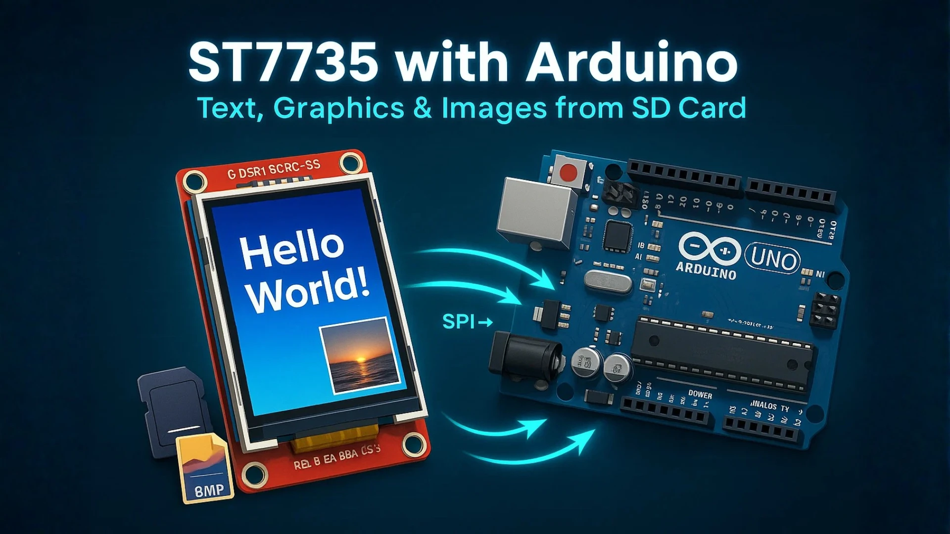
Interfacing ST7735 TFT Display with Arduino – Display Text, Graphics, and Images from SD Card
How to Interface MAX7219 7 Segment Display with Arduino | Display Text, Scrolling Message, and Time
Arduino ST7920 Tutorial (128×64 LCD): Wiring, Setup, U8g2, and Text Display Guide
Arduino ST7920 Display Graphics Guide: Shapes, Icons, Bitmaps, and UI Design
Arduino ST7920 Graphics Guide: How to Create Scrolling Text, Animations and Page Transitions (U8g2)
ST7920 Arduino Projects Tutorial: Real-Time Graphs, Menu System, and Full Dashboard UI using U8g2
Arduino SH1106 Oled Project Download
Arduino SH1106 Oled FAQs
Subscribe
Login
0 Comments
Newest
