Published: November 22, 2025
Last Updated: February 6, 2026
Last Updated: February 6, 2026
Interfacing ADXL345 with Arduino using I2C (Complete Beginner-Friendly Tutorial)
Accelerometers are used everywhere – in mobile phones, drones, robotics, and IoT projects. The ADXL345 accelerometer is one of the most popular and affordable sensors for measuring acceleration in three axes. It works on the I2C bus, so connecting it with an Arduino is simple and reliable.
In this tutorial, you will learn how to interface the ADXL345 with Arduino using I2C. We will look at its pinout, wiring, features, and why it is preferred over many other accelerometers. You will also learn how to read raw X, Y, Z values, convert them into g-force, and even calibrate the sensor for accurate results.
This guide uses short sentences, simple words, and clear steps, making it perfect for beginners and hobbyists. By the end, you will have a fully working setup and clean Arduino code that you can use in real robotics and IoT projects.
Table Of Contents
- What is ADXL345 Accelerometer?
- ADXL345 Pinout and Specifications
- ADXL345 vs MPU6050
- Wiring ADXL345 with Arduino via I2C
- Reading Raw Accelerometer Values from ADXL345
- Convert Raw Accelerometer Values to ‘g’ Units
- ADXL345 Calibration for All 3 Axes
- Tilt Angle Calculation Using ADXL345 (Pitch & Roll)
- Final Complete Code : Raw Values, g-Values, Calibration, Pitch & Roll
- Conclusion
What is ADXL345 Accelerometer?
The ADXL345 is a small, low-power 3-axis digital accelerometer. It measures acceleration in the X, Y, and Z directions. This makes it useful for detecting tilt, motion, vibration, and orientation. Because it uses I2C communication, it connects easily to most microcontrollers, especially Arduino boards.
The sensor is stable, accurate, and works well in many electronics and IoT projects. Its compact size and low cost make it a good choice for beginners, hobbyists, and even professional designs.
Key Features of the ADXL345
- 3-axis acceleration measurement (X, Y, Z)
- I2C and SPI communication support
- High resolution up to 13 bits, giving smooth and precise readings
- Selectable measurement range: ±2g, ±4g, ±8g, ±16g
- Low power consumption, ideal for battery-powered devices
- Tap, double-tap, free-fall, and activity detection built-in
- Small size, easy to mount on compact PCBs
- Output data rates up to 3200 Hz, useful for high-speed motion sensing
Why ADXL345 is Popular in Arduino Projects
The ADXL345 is widely used in Arduino projects because:
- It uses I2C, which needs only two wires (SDA and SCL).
- Libraries for Arduino are easy to find and simple to use.
- It gives clean and stable readings, even without heavy filtering.
- It supports multiple sensitivity levels, making it suitable for robotics and wearables.
- It works from a 3.3V supply, which is safe for most projects.
- Its low price makes it ideal for beginner tutorials and student projects.
Whether you are building a tilt sensor, gesture controller, or basic IMU project, the ADXL345 fits well.
Advantages and Disadvantages of ADXL345
Advantages
- Easy to interface using I2C
- High-resolution output for smooth acceleration data
- Supports multiple g-ranges for flexible applications
- Built-in motion detection functions
- Very low power usage
- Affordable and widely available
Disadvantages
- Only measures acceleration, not gyroscope data
- Requires careful calibration for accurate readings
- Performance drops slightly in high-vibration environments
- Not as advanced as 6-axis IMUs like MPU6050
ADXL345 Pinout and Specifications
The ADXL345 has a simple pinout and supports digital communication, which makes it easy to connect with Arduino. In this section, we will look at each pin, its purpose, and the electrical specifications you must know before wiring the sensor.
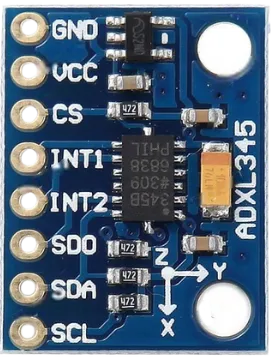
ADXL345 Pinout Explained
The ADXL345 module usually comes with 8 pins. Each pin has a specific role in communication, power, and configuration. The image below shows the pinout for the ADXL345 sensor breakout board.
Here is the pinout table for quick reference:
| Pin Name | Function | Description |
|---|---|---|
| VCC | Power | Connects to 3.3V supply. Some modules have onboard regulators and can accept 5V. |
| GND | Ground | Connects to Arduino ground. |
| SDA | I2C Data | Used for data transfer in I2C communication. |
| SCL | I2C Clock | Provides clock signal for I2C communication. |
| CS | Chip Select | Selects SPI mode (pull high for I2C mode). |
| SDO | Address Select | Defines I2C address (LOW = 0x53, HIGH = 0x1D). |
| INT1 | Interrupt 1 | Used for motion, tap, free-fall detection. |
| INT2 | Interrupt 2 | Additional interrupt pin for advanced functions. |
These pins allow the ADXL345 to work with both I2C and SPI, but I2C is the most commonly used mode in Arduino projects.
Power Requirements and I2C Address
The ADXL345 operates at 3.3V. However, many breakout boards include a 3.3V regulator, allowing you to power the module directly from 5V Arduino boards like the Uno or Nano.
- Operating Voltage: 2.0V to 3.6V (core chip)
- Typical Module Input: 3.3V or 5V depending on board version
- Communication Levels: 3.3V logic (most breakout boards include level shifting)
I2C Addresses:
The ADXL345 supports two possible I2C addresses:
- 0x53 → When SDO = LOW (GND)
- 0x1D → When SDO = HIGH (3.3V)
Most modules set SDO to LOW, so the default I2C address is 0x53.
Operating Range and Measurement Capabilities
The ADXL345 is a full-featured accelerometer with flexible measurement ranges and high resolution. This makes it suitable for both low-speed tilt detection and high-speed motion tracking.
Operating Range:
| Measurement Range (g) | Sensitivity (LSB/g) |
|---|---|
| ±2g | 256 LSB/g |
| ±4g | 128 LSB/g |
| ±8g | 64 LSB/g |
| ±16g | 32 LSB/g |
Capabilities:
- 3-axis measurement (X, Y, Z)
- Resolution: Up to 13 bits
- Output Data Rate (ODR): 0.1 Hz to 3200 Hz
- Noise Level: Low, stable readings
- Built-in Detection Features:
- Tap and double-tap
- Free-fall detection
- Activity and inactivity monitoring
This combination of accuracy, flexibility, and stability makes the ADXL345 a reliable choice for Arduino motion-sensing projects.
ADXL345 vs MPU6050
The ADXL345 and MPU6050 are two of the most popular motion sensors used in Arduino and IoT projects. Both are reliable, affordable, and easy to use. However, they differ in features, accuracy, and applications. In this section, we compare both sensors so you can choose the right one for your project.
The table below shows the major differences between the ADXL345 (accelerometer only) and MPU6050 (accelerometer + gyroscope).
| Feature | ADXL345 | MPU6050 |
|---|---|---|
| Sensor Type | 3-axis accelerometer | 3-axis accelerometer + 3-axis gyroscope |
| Communication | I2C / SPI | I2C |
| Operating Voltage | 2.0V – 3.6V | 2.3V – 3.4V |
| I2C Address | 0x53 or 0x1D | 0x68 or 0x69 |
| Measurement Range | ±2g, ±4g, ±8g, ±16g | Accel: ±2g to ±16g Gyro: ±250°/s to ±2000°/s |
| Resolution | Up to 13 bits | 16 bits (accel), 16 bits (gyro) |
| Built-in Features | Tap, double-tap, free-fall, activity detection | DMP (Digital Motion Processor) on some variants |
| Power Consumption | Very low | Moderate |
| Use Case | Tilt, vibration, orientation | Motion tracking, balancing, robotics |
| Price | Low | Slightly higher |
| Ease of Use | Very easy | Easy, but requires more processing for gyro data |
This makes the ADXL345 ideal for simple acceleration-based projects, while the MPU6050 suits more advanced motion-tracking applications.
Which Sensor Should You Choose?
Choosing between ADXL345 and MPU6050 depends on your project needs:
Choose ADXL345 if:
- You only need acceleration data
- Your project must be low power, like wearables or battery-based IoT sensors
- You want easy wiring and simple Arduino code
- You need built-in tap or free-fall detection
- Your project involves tilt sensing, vibration detection, or simple motion
Choose MPU6050 if:
- You need both acceleration and gyroscope data
- Your project requires real-time orientation, such as drones or self-balancing robots
- You need high accuracy and stable long-term tracking
- You want to use the DMP engine for sensor fusion
Wiring ADXL345 with Arduino via I2C
Connecting the ADXL345 to Arduino using I2C is simple and beginner-friendly. You only need two signal wires (SDA and SCL) along with power and ground. In this section, we list the components, show the wiring, and share some helpful tips to avoid common mistakes.
Components Needed
You will need the following components:
- ADXL345 Accelerometer Module
- Arduino Board (Uno, Nano, Mega, etc.)
- Male-to-Female Jumper Wires
- Breadboard (optional but helpful)
Most ADXL345 modules come with onboard 3.3V regulation, so you can connect them easily to Arduino’s 5V supply.
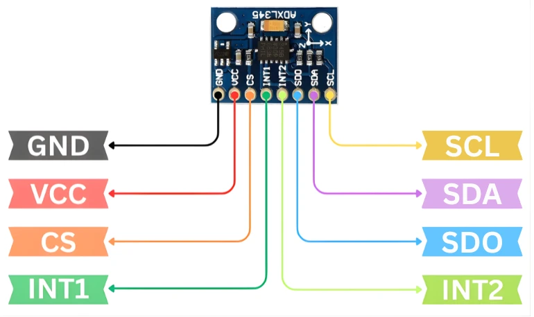
Circuit Diagram and Connections (I2C)
The ADXL345 supports I2C communication by default. The image below shows the wiring between ADXL345 and Arduino UNO.
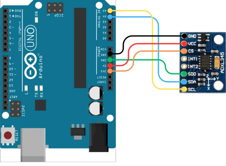
Here is the table for the connections:
| ADXL345 Pin | Connect To (Arduino Uno/Nano) | Function |
|---|---|---|
| VCC | 3.3V or 5V* | Power supply |
| GND | GND | Ground |
| SDA | A4 | I2C Data line |
| SCL | A5 | I2C Clock line |
| CS | 3.3V | Forces I2C mode |
| SDO | GND | Sets I2C address to 0x53 |
| INT1 / INT2 | Optional | Interrupt outputs |
Note: If your ADXL345 board has a voltage regulator and logic level shifter, VCC can be connected to 5V.
If not, only use 3.3V.
Common Mistakes to Avoid While Wiring
Even though wiring is simple, beginners often make small mistakes that cause the sensor to fail. Avoid these issues:
1. Supplying 5V to a Non-Regulated Module
Some ADXL345 boards are 3.3V-only. Supplying 5V will damage the chip. Always check your breakout board.
2. Leaving CS Floating
If CS is not tied HIGH, the sensor may enter SPI mode or stay unstable. Always connect CS to 3.3V for I2C.
3. Wrong I2C Pins on Arduino
Different Arduino boards have different I2C pins.
- Uno/Nano: A4 (SDA), A5 (SCL)
- Mega: 20 (SDA), 21 (SCL)
Verify them before wiring.
4. Mixing Up SDA and SCL
Swapping these two will cause the sensor to not respond at all.
5. Not Connecting SDO to Ground
If SDO is floating, the I2C address becomes unpredictable. Tie SDO to GND for address 0x53.

Reading Raw Accelerometer Values from ADXL345
In this section, we set up the ADXL345 in I2C mode, configure important registers, and read raw acceleration values from the X, Y, and Z axes.
Arduino Code to Initialize ADXL345 (I2C Mode)
#include <Wire.h>

#define ADXL345_ADDR 0x53

void setup() {
  Serial.begin(9600);
  Wire.begin();

  // --- Put ADXL345 into Measurement Mode ---
  Wire.beginTransmission(ADXL345_ADDR);
  Wire.write(0x2D);     // POWER_CTL register
  Wire.write(0x08);     // Measurement mode ON
  Wire.endTransmission();

  // --- Set Full Resolution Mode (10-bit to 13-bit depending on g-range) ---
  Wire.beginTransmission(ADXL345_ADDR);
  Wire.write(0x31);     // DATA_FORMAT register
  Wire.write(0x08);     // Full Resolution + ±2g range
  Wire.endTransmission();

  // --- Set Data Rate to 100 Hz ---
  Wire.beginTransmission(ADXL345_ADDR);
  Wire.write(0x2C);     // BW_RATE register
  Wire.write(0x0A);     // 100 Hz output data rate
  Wire.endTransmission();

  Serial.println("ADXL345 Initialized...");
}

void loop() {
  int16_t xRaw, yRaw, zRaw;

  // Select starting register
  Wire.beginTransmission(ADXL345_ADDR);
  Wire.write(0x32);
  Wire.endTransmission(false);

  // Read 6 bytes for X, Y, Z
  Wire.requestFrom(ADXL345_ADDR, 6, true);

  xRaw = (Wire.read() | (Wire.read() << 8));
  yRaw = (Wire.read() | (Wire.read() << 8));
  zRaw = (Wire.read() | (Wire.read() << 8));

  Serial.print("X Raw: "); Serial.print(xRaw);
  Serial.print("  | Y Raw: "); Serial.print(yRaw);
  Serial.print("  | Z Raw: "); Serial.println(zRaw);

  delay(300);
}Explanation for setup () function
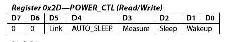
Enabling Measurement Mode (POWER_CTL – 0x2D)
- The ADXL345 starts in standby mode.
- Writing
0x08turns ON the measurement. - The sensor now starts producing acceleration data.
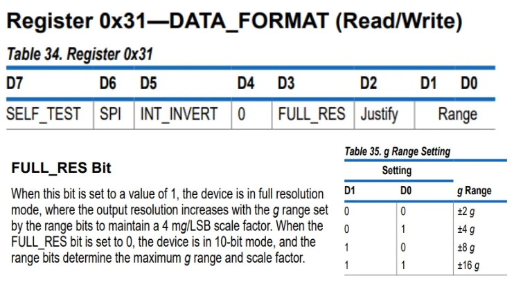
Setting Data Format (DATA_FORMAT – 0x31)
- Writing
0x08enables:- Full resolution mode
- ±2g range
- Full resolution keeps accuracy consistent even if range changes.
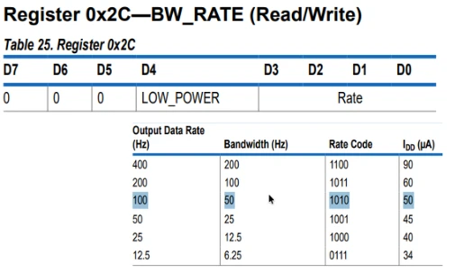
Setting Output Data Rate (BW_RATE – 0x2C)
- Writing
0x0Asets the sampling rate to 100 Hz. - This update rate is stable for most Arduino projects.
Reading Values in loop()
Selecting Register 0x32
- Register 0x32 is the start of the X-axis LSB.
- Then the sensor automatically sends the next 5 bytes.
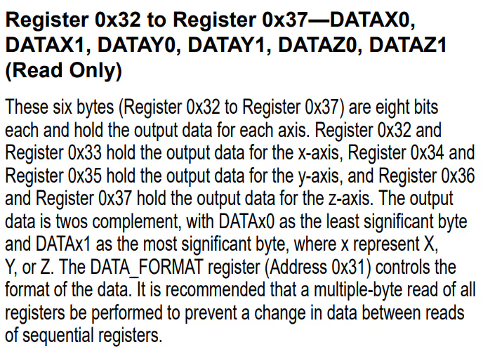
Combining LSB + MSB
- ADXL345 gives each axis as a 16-bit signed value.
- We combine them using bit-shifting.
Printing Raw Values
- These are NOT in g units yet.
- They help verify that the sensor is working.
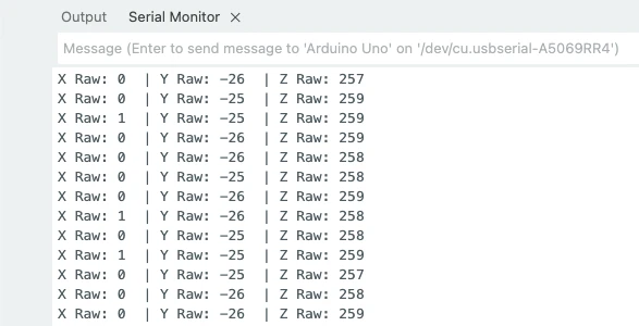
Output on the serial Monitor
The image below shows the Raw X, Y and Z values printed on the serial monitor.
Convert Raw Accelerometer Values to ‘g’ Units
Now we convert the raw ADC readings into real acceleration values measured in g-force. This makes the data more meaningful for tilt detection and motion analysis.
Understanding Sensitivity and Scale Factor
- In full-resolution mode, sensitivity stays roughly 256 LSB per g at ±2g.
- Formula to convert raw to g:
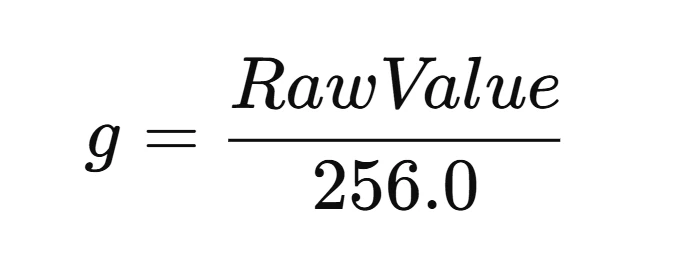
- If you later switch range (±4g, ±8g, ±16g), the scale factor adjusts automatically in full-resolution mode.
Arduino Code to Convert Raw Values to g
Here is the full code combining initialization, raw reading, and g-value conversion:
#include <Wire.h>

#define ADXL345_ADDR 0x53

float scaleFactor = 256.0; // For ±2g full-resolution mode

void setup() {
  Serial.begin(9600);
  Wire.begin();

  // Measurement Mode
  Wire.beginTransmission(ADXL345_ADDR);
  Wire.write(0x2D);
  Wire.write(0x08);
  Wire.endTransmission();

  // Full resolution mode ±2g
  Wire.beginTransmission(ADXL345_ADDR);
  Wire.write(0x31);
  Wire.write(0x08);
  Wire.endTransmission();

  // Data rate 100 Hz
  Wire.beginTransmission(ADXL345_ADDR);
  Wire.write(0x2C);
  Wire.write(0x0A);
  Wire.endTransmission();

  Serial.println("ADXL345 Ready...");
}

void loop() {
  int16_t xRaw, yRaw, zRaw;

  Wire.beginTransmission(ADXL345_ADDR);
  Wire.write(0x32);
  Wire.endTransmission(false);

  Wire.requestFrom(ADXL345_ADDR, 6, true);

  xRaw = (Wire.read() | (Wire.read() << 8));
  yRaw = (Wire.read() | (Wire.read() << 8));
  zRaw = (Wire.read() | (Wire.read() << 8));

  // Convert to g
  float xg = xRaw / scaleFactor;
  float yg = yRaw / scaleFactor;
  float zg = zRaw / scaleFactor;

  Serial.print("X (g): "); Serial.print(xg);
  Serial.print("  | Y (g): "); Serial.print(yg);
  Serial.print("  | Z (g): "); Serial.println(zg);

  delay(300);
}Explanation
scaleFactor = 256.0
- Because the sensor is in full-resolution ±2g mode.
- Always divide raw values by this factor.
Conversion
Example: If X raw = 512, 512/256=2g
Meaning of g Values
- 1g = force of Earth’s gravity.
- Z-axis will normally show ~1g when the sensor lies flat.
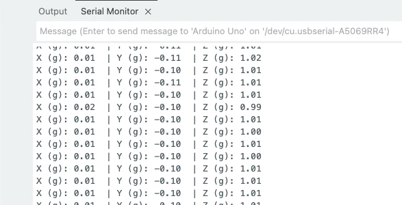
Output on the serial Monitor
The image below shows the ADXL345 converted values (in g format) are printed on the serial console.
ADXL345 Calibration for All 3 Axes
In this section, we correct the natural offset errors of the ADXL345 sensor. Calibration improves accuracy and gives more stable values for robotics, motion detection, and tilt measurement.
Why Do We Need Calibration?
Even when the ADXL345 is perfectly still, the raw values are usually not zero.
This happens because of:
- Small manufacturing differences
- Electrical noise
- Slight sensor tilt
- Board-level imperfections
These small errors create offsets. Calibration removes these offsets so your readings become accurate and stable.
Steps to Calibrate X, Y, Z Axes
Follow these steps to get clean offsets from the ADXL345:
Place the Sensor on a Flat Surface
- The surface should be stable and level.
- Z-axis should read near +1g.
- X and Y should read 0g ideally.
Read Raw Values Multiple Times
- Take 100–200 samples.
- Average them to reduce noise.
Calculate Offsets
- Offset for X = average_X
- Offset for Y = average_Y
- Offset for Z = average_Z − 256 (because 1g = 256 LSB at ±2g)
Subtract Offsets from Future Readings
- New_X = Raw_X − offsetX
- New_Y = Raw_Y − offsetY
- New_Z = Raw_Z − offsetZ
This ensures your readings start close to:
X ≈ 0g
Y ≈ 0g
Z ≈ 1g Arduino Code for 3-Axis Calibration
Below is a simple calibration code that reads many samples, averages them, and prints the final offsets.
#include <Wire.h>

#define ADXL345_ADDR 0x53

int16_t xRaw, yRaw, zRaw;
long xSum = 0, ySum = 0, zSum = 0;
int samples = 200;

void setup() {
  Serial.begin(9600);
  Wire.begin();

  // Measurement Mode
  Wire.beginTransmission(ADXL345_ADDR);
  Wire.write(0x2D);
  Wire.write(0x08);
  Wire.endTransmission();

  // Full resolution mode ±2g
  Wire.beginTransmission(ADXL345_ADDR);
  Wire.write(0x31);
  Wire.write(0x08);
  Wire.endTransmission();

  delay(200);
  Serial.println("Starting Calibration...");

  // --- Take multiple readings ---
  for (int i = 0; i < samples; i++) {

    Wire.beginTransmission(ADXL345_ADDR);
    Wire.write(0x32);
    Wire.endTransmission(false);

    Wire.requestFrom(ADXL345_ADDR, 6, true);

    xRaw = (Wire.read() | (Wire.read() << 8));
    yRaw = (Wire.read() | (Wire.read() << 8));
    zRaw = (Wire.read() | (Wire.read() << 8));

    xSum += xRaw;
    ySum += yRaw;
    zSum += zRaw;

    delay(5);
  }

  // --- Average values ---
  float xOffset = xSum / samples;
  float yOffset = ySum / samples;
  float zOffset = (zSum / samples) - 256.0; // Z should read ~1g at rest

  Serial.println("Calibration Complete:");
  Serial.print("X Offset: "); Serial.println(xOffset);
  Serial.print("Y Offset: "); Serial.println(yOffset);
  Serial.print("Z Offset: "); Serial.println(zOffset);

  Serial.println("Use these offsets in your main code.");
}

void loop() {
  // Nothing here – calibration runs in setup()
}Short Explanation of New Things
Averaging Samples
- Reduces noise and gives a stable calibration value.
Why subtract 256 from Z?
- Z-axis reads +1g when the board is flat.
- In raw values:
- 1g ≈ 256 LSB
- So we subtract this to make calibrated Z ≈ 1g when level.
Output on the serial console
Place the module on a flat surface and run the calibration code. The image below shows the output of the code.
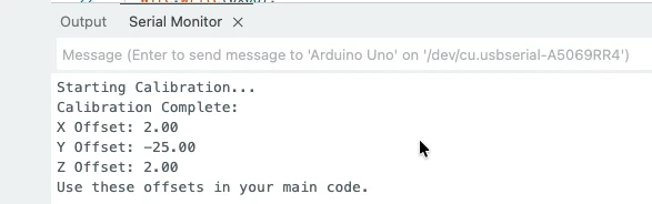
We will use these values in our final code to calibrate the sensor.
Tilt Angle Calculation Using ADXL345 (Pitch & Roll)
In this section, we learn how to calculate tilt angles using the ADXL345 accelerometer. With just the acceleration values (Ax, Ay, Az), we can compute the Pitch and Roll of the sensor. This method works best when the device is stationary or moving slowly, because it relies only on gravity.
How Tilt Angle Calculation Works
The ADXL345 gives us acceleration along X, Y, and Z axes in g units.
When the sensor tilts, the direction of gravity changes across these axes. Using this shift, we can compute angles:
- Pitch → rotation forward/backward
- Roll → rotation left/right
We use the standard accelerometer formula (Option A):
Pitch = atan2( Ax , √(Ay² + Az²) )
Roll = atan2( Ay , √(Ax² + Az²) )We convert the result from radians to degrees.
Full Arduino Code for Pitch & Roll (Raw + g + Calibration)
The code below includes: Initialization, Calibration, Raw reading, Convert to g, Pitch & Roll angle calculation and Serial output.
Below is the Complete Code :
// Full ADXL345 Tilt Angle Code (Pitch & Roll)
// Includes: initialization, calibration, raw values, g-values, pitch, roll
#include <Wire.h>
#define ADXL345_ADDR 0x53 // SDO = GND
const float SCALE_FACTOR = 256.0; // LSB/g in full-resolution mode
const int CAL_SAMPLES = 200;
const unsigned long LOOP_DELAY_MS = 200;
float xOffset = 0.0, yOffset = 0.0, zOffset = 0.0;
// Write to ADXL345 register
void adxlWrite(uint8_t reg, uint8_t value) {
Wire.beginTransmission(ADXL345_ADDR);
Wire.write(reg);
Wire.write(value);
Wire.endTransmission();
}
// Setup registers
void initADXL345() {
adxlWrite(0x2D, 0x08); // POWER_CTL: measurement mode
adxlWrite(0x31, 0x08); // DATA_FORMAT: full resolution, ±2g
adxlWrite(0x2C, 0x0A); // BW_RATE: 100 Hz
}
// Read 6 bytes from DATAX0
void readRaw(int16_t &x, int16_t &y, int16_t &z) {
Wire.beginTransmission(ADXL345_ADDR);
Wire.write(0x32); // DATAX0
Wire.endTransmission(false);
Wire.requestFrom(ADXL345_ADDR, 6, true);
x = (int16_t)(Wire.read() | (Wire.read() << 8));
y = (int16_t)(Wire.read() | (Wire.read() << 8));
z = (int16_t)(Wire.read() | (Wire.read() << 8));
}
// Average-based calibration
void calibrate() {
Serial.println("Calibration: keep sensor flat and still...");
long xSum = 0, ySum = 0, zSum = 0;
for (int i = 0; i < CAL_SAMPLES; i++) {
int16_t xr, yr, zr;
readRaw(xr, yr, zr);
xSum += xr;
ySum += yr;
zSum += zr;
delay(5);
}
float xAvg = xSum / CAL_SAMPLES;
float yAvg = ySum / CAL_SAMPLES;
float zAvg = zSum / CAL_SAMPLES;
// X & Y should be 0g, Z should be +1g
xOffset = xAvg;
yOffset = yAvg;
zOffset = zAvg - SCALE_FACTOR;
Serial.println("Offsets calculated:");
Serial.print("X Offset: "); Serial.println(xOffset);
Serial.print("Y Offset: "); Serial.println(yOffset);
Serial.print("Z Offset: "); Serial.println(zOffset);
Serial.println();
}
void setup() {
Serial.begin(9600);
Wire.begin();
delay(50);
initADXL345();
delay(50);
calibrate();
Serial.println("Starting angle calculations...\n");
}
void loop() {
int16_t xRaw, yRaw, zRaw;
readRaw(xRaw, yRaw, zRaw);
// Apply offsets
float xCal = xRaw - xOffset;
float yCal = yRaw - yOffset;
float zCal = zRaw - zOffset;
// Convert to g
float Ax = xCal / SCALE_FACTOR;
float Ay = yCal / SCALE_FACTOR;
float Az = zCal / SCALE_FACTOR;
// Tilt Angle Calculation (Option A)
float pitch = atan2(Ax, sqrt(Ay * Ay + Az * Az)) * 180.0 / PI;
float roll = atan2(Ay, sqrt(Ax * Ax + Az * Az)) * 180.0 / PI;
// Print output
Serial.print("Pitch: "); Serial.print(pitch, 2); Serial.print("° ");
Serial.print("Roll: "); Serial.print(roll, 2); Serial.println("°");
delay(LOOP_DELAY_MS);
}Code Explanation
1. Initialization
- Sensor enters measurement mode.
- Full resolution is enabled for best accuracy.
- Data rate set to 100 Hz for stable readings.
2. Calibration
- Collects ~200 readings.
- Averages static values to calculate offsets.
- X, Y = 0g when flat; Z = +1g.
3. Raw & g-value conversion
- Reads 16-bit raw acceleration data.
- Subtracts offsets.
- Converts to g units using scale factor.
4. Tilt Angle Calculation
Using standard accelerometer-only formulas:
Pitch = atan2( Ax , √(Ay² + Az²) )
Roll = atan2( Ay , √(Ax² + Az²) )These detect tilt even without a gyroscope.
5. Output
- Prints Pitch & Roll in degrees.
- Updates every 200 ms.
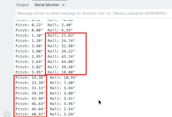
Output on the serial monitor
The image below shows the change in roll and pitch values when the sensor is rotated around x and y axes respectively.
Final Complete Code : Raw Values, g-Values, Calibration, Pitch & Roll
This section gives you the complete, fully working Arduino code that includes every feature we covered in this tutorial. Instead of testing each part separately, this final sketch brings everything together into one clean and organized program. It handles the entire workflow of the ADXL345 — from initialization to final tilt-angle calculation.
With this code, you can:
- Initialize the ADXL345 in full-resolution mode
- Configure important registers
- Perform automatic 3-axis calibration
- Read raw X, Y, and Z acceleration values
- Convert raw data into accurate g-values
- Calculate Pitch and Roll tilt angles
- Print all readings neatly on the Serial Monitor
This is the most complete and polished version of the project. You can plug this directly into any Arduino, upload it, and start getting stable, accurate accelerometer and tilt-angle readings. It’s perfect for robotics, motion-tracking, self-balancing systems, and IoT applications that depend on precise orientation data.
Below is the Complete Code :
// Full ADXL345 sketch:
// - Init (full resolution, 100Hz)
// - Auto calibration (200 samples)
// - Read raw values
// - Convert to g
// - Compute Pitch & Roll (Option A)
// - Print Raw, g, Pitch, Roll

#include <Wire.h>

#define ADXL345_ADDR 0x53   // SDO = GND

const float SCALE_FACTOR = 256.0;   // LSB per g in full-res ±2g mode
const int CAL_SAMPLES = 200;
const unsigned long LOOP_DELAY_MS = 200;

float xOffset = 0.0;
float yOffset = 0.0;
float zOffset = 0.0;

void adxlWriteRegister(uint8_t reg, uint8_t value) {
  Wire.beginTransmission(ADXL345_ADDR);
  Wire.write(reg);
  Wire.write(value);
  Wire.endTransmission();
}

void setupADXL345() {
  // Measurement mode
  adxlWriteRegister(0x2D, 0x08);   // POWER_CTL: Measure bit = 1

  // Full resolution, ±2g
  adxlWriteRegister(0x31, 0x08);   // DATA_FORMAT: Full res

  // Data rate = 100 Hz
  adxlWriteRegister(0x2C, 0x0A);   // BW_RATE: 0x0A => 100 Hz
}

void readRawXYZ(int16_t &x, int16_t &y, int16_t &z) {
  Wire.beginTransmission(ADXL345_ADDR);
  Wire.write(0x32);            // DATAX0
  Wire.endTransmission(false);

  Wire.requestFrom(ADXL345_ADDR, 6, true);
  x = (int16_t)(Wire.read() | (Wire.read() << 8));
  y = (int16_t)(Wire.read() | (Wire.read() << 8));
  z = (int16_t)(Wire.read() | (Wire.read() << 8));
}

void calibrateSensor() {
  Serial.println("Calibration: Keep sensor flat and still...");
  long xSum = 0, ySum = 0, zSum = 0;

  for (int i = 0; i < CAL_SAMPLES; i++) {
    int16_t xr, yr, zr;
    readRawXYZ(xr, yr, zr);
    xSum += xr;
    ySum += yr;
    zSum += zr;
    delay(5);
  }

  float xAvg = (float)xSum / CAL_SAMPLES;
  float yAvg = (float)ySum / CAL_SAMPLES;
  float zAvg = (float)zSum / CAL_SAMPLES;

  // Offsets to subtract from raw readings
  xOffset = xAvg;                // X should be ~0g when flat
  yOffset = yAvg;                // Y should be ~0g when flat
  zOffset = zAvg - SCALE_FACTOR; // Z should be ~1g (≈ SCALE_FACTOR) when flat

  Serial.println("Calibration complete.");
  Serial.print("X Offset: "); Serial.println(xOffset);
  Serial.print("Y Offset: "); Serial.println(yOffset);
  Serial.print("Z Offset: "); Serial.println(zOffset);
  Serial.println();
  delay(200);
}

void setup() {
  Serial.begin(9600);
  Wire.begin();
  delay(50);

  setupADXL345();
  delay(50);

  Serial.println("ADXL345 initialized (Full res, 100Hz).");
  calibrateSensor();
  Serial.println("Starting readings...");
  Serial.println();
}

void loop() {
  int16_t xRaw, yRaw, zRaw;
  readRawXYZ(xRaw, yRaw, zRaw);

  // Apply calibration offsets (raw)
  float xCal = (float)xRaw - xOffset;
  float yCal = (float)yRaw - yOffset;
  float zCal = (float)zRaw - zOffset;

  // Convert to g
  float xg = xCal / SCALE_FACTOR;
  float yg = yCal / SCALE_FACTOR;
  float zg = zCal / SCALE_FACTOR;

  // Compute Pitch & Roll (Option A)
  // Pitch = atan2( Xg , sqrt(Yg^2 + Zg^2) )
  // Roll  = atan2( Yg , sqrt(Xg^2 + Zg^2) )
  float pitch = atan2(xg, sqrt(yg * yg + zg * zg)) * 180.0 / PI;
  float roll  = atan2(yg, sqrt(xg * xg + zg * zg)) * 180.0 / PI;

  // Print Raw + g + angles
  Serial.print("RawX: "); Serial.print(xRaw);
  Serial.print(" RawY: "); Serial.print(yRaw);
  Serial.print(" RawZ: "); Serial.print(zRaw);

  Serial.print("  ||  X(g): "); Serial.print(xg, 3);
  Serial.print(" Y(g): "); Serial.print(yg, 3);
  Serial.print(" Z(g): "); Serial.print(zg, 3);

  Serial.print("  ||  Pitch: "); Serial.print(pitch, 2);
  Serial.print("°  Roll: "); Serial.print(roll, 2);
  Serial.println("°");

  delay(LOOP_DELAY_MS);
}Code Explanations
1) Initialization (setupADXL345)
- Puts ADXL345 into measurement mode (POWER_CTL 0x2D = 0x08).
- Enables full-resolution at ±2g (DATA_FORMAT 0x31 = 0x08).
- Sets data rate to 100 Hz (BW_RATE 0x2C = 0x0A).
- Short: this prepares the sensor to give stable, high-resolution readings.
2) Reading raw values (readRawXYZ)
- Starts at register 0x32 (DATAX0) and reads 6 bytes.
- Combines LSB + MSB for each axis into signed 16-bit values.
- Short: gives direct raw counts from the sensor.
3) Calibration (calibrateSensor)
- Collects
CAL_SAMPLES(200) quick readings and averages them. - Sets
xOffsetandyOffsetto the average raw values (should be ≈0g). - Sets
zOffsetto average minusSCALE_FACTOR(because Z ≈ +1g at rest). - Short: find and store the offsets to remove static bias.
4) Applying offsets & converting to g
- Subtract offsets from raw values:
xCal = xRaw - xOffset. - Convert to g using
SCALE_FACTOR = 256.0(full-res ±2g):xg = xCal / 256.0. - Short: gives physical acceleration in g (1g ≈ Earth’s gravity).
5) Pitch & Roll (Option A)
pitch = atan2(Xg, sqrt(Yg^2 + Zg^2))roll = atan2(Yg, sqrt(Xg^2 + Zg^2))- Short: uses accelerometer-only math to compute tilt; works well when device is relatively still.
6) Output
- Serial prints Raw counts, converted g-values (3 decimals), and Pitch/Roll angles (2 decimals).
- Short: easy to copy/paste or visualize with Serial Plotter.
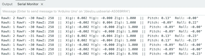
Output on Serial Monitor
The image below shows the RAW X, Y and Z values along with values in g format as well. You can also see the Pitch and Roll values.
Notes, tips & optional improvements
- Offsets in sensor registers: You can write 8-bit offsets into registers 0x1E–0x20. They are low resolution (15.6 mg steps). I used software offsets because they are more precise.
- Calibration: Make sure the sensor is flat, stable and not moving while calibrating.
- If angles jitter when moving: accelerometer alone gives noisy angles during motion. Consider a complementary filter or add a gyroscope (IMU) for sensor fusion.
- If readings unstable: shorten wires, add decoupling cap (0.1µF) near sensor VCC, or reduce I2C speed.
- If using a 5V Arduino: ensure your ADXL345 module has a regulator and level shifter before connecting 5V to VCC. Otherwise power with 3.3V.
Conclusion
In this tutorial, we covered the ADXL345 accelerometer from start to finish, building a strong understanding of how it works and how to use it effectively with Arduino. We began by exploring how to read raw acceleration values directly from the sensor and explained what these numbers actually represent. Then we learned how to convert these raw values into accurate g-force units using the sensor’s sensitivity and scale factor. This step is crucial because it transforms the unreadable raw data into clear, meaningful information that you can use in any project.
We also discussed the importance of calibrating all three axes: X, Y, and Z. Without proper calibration, the sensor will always show small errors, even when it is perfectly still. You learned why calibration is required, how to perform it correctly, and how to apply offsets to improve accuracy. We also clarified whether offsets can be stored inside the sensor registers and when to use 0g positions for calibration.
Finally, we combined everything into a complete, final Arduino code that includes raw readings, g-value conversion, and full 3-axis calibration. With the line-by-line explanation and troubleshooting tips, you now have a fully working and reliable template to use the ADXL345 in real-world applications like robotics, motion tracking, IoT devices, gesture detection, and vibration monitoring.
Browse More Arduino Sensors Tutorials

Interfacing SHT3X Temperature and Humidity Sensors with Arduino using I2C
MPU6050 Arduino I2C Tutorial: Pinout, Wiring, Calibration, Raw Data, and Code Examples
Interfacing BMP180 Sensor with Arduino: Measure Temperature, Pressure Altitude with LCD1602 I2C
Interface SHT21 Temperature and Humidity Sensor with Arduino | Display on Serial Monitor and I2C LCD
Interface DHT11 and DHT22 with Arduino | Temperature and Humidity Sensor Tutorial
Arduino DS18B20 Temperature Sensor Tutorial: Single and Multiple Sensors with SSD1306 OLED
How to Interface GP2Y0A41SK0F Distance Sensor with Arduino (Serial Monitor + I2C LCD Display)
Arduino ADXL345 Project Download
Arduino ADXL345 FAQs
Subscribe
Login
0 Comments
Newest
