Published: October 24, 2017
Last Updated: March 23, 2026
Last Updated: March 23, 2026
How to Generate PWM Signal with DMA in STM32
Pulse Width Modulation (PWM) is one of the most common techniques in embedded systems. In simple words, PWM controls the amount of power delivered to devices by switching a signal on and off very fast. Because of this, you can dim an LED, control the speed of a motor, or even generate audio signals with just a microcontroller pin.
In STM32 microcontrollers, PWM generation becomes very simple because the timers have built-in support. You only need to configure the timer, select the channel, and set the frequency and duty cycle. After that, the hardware takes care of generating a clean PWM signal.
Compared to manually toggling GPIOs, using timers is much more accurate and efficient. As a result, PWM in STM32 is widely used in robotics, automation, motor drivers, LED brightness control, and many other real-world projects.
In this tutorial, you will learn step by step how to configure PWM on STM32 using STM32CubeMX and the HAL library. First, we will look at the basic concept of PWM and timers. Then, we will configure the project in CubeMX, generate code, and finally test the output on real hardware.
What is PWM (Pulse Width Modulation)?
Pulse Width Modulation, commonly known as PWM, is a widely used technique for controlling the average voltage or power delivered to an electronic device. Instead of smoothly varying the voltage level, PWM works by rapidly switching a digital signal ON and OFF at a fixed rate. Even though the signal itself is digital, the device connected to it responds to the average effect of this switching, which behaves like an analog control.
The key concept behind PWM is the amount of time the signal remains ON compared to the time it remains OFF during one complete switching cycle. This ratio is known as the duty cycle, and it is usually expressed as a percentage. The speed at which the signal switches ON and OFF is called the frequency, and it determines how often one complete PWM cycle repeats per second.
For example, a 50% duty cycle means the signal is ON for half of the cycle and OFF for the other half. In this case, the device receives roughly half of the maximum possible power. If the duty cycle is increased to 75%, the signal stays ON longer, delivering more power. If it is reduced to 25%, the signal stays OFF longer, resulting in less power being delivered. By simply changing the duty cycle, we can precisely control the behavior of many devices.
PWM is commonly used in practical applications such as dimming LEDs, where the brightness changes according to the duty cycle, controlling motor speed, where higher duty cycles produce higher speeds, and regulating heater power, where PWM adjusts the amount of heat generated. Since the switching happens very quickly, the human eye or the mechanical system perceives the output as smooth and continuous.
One of the biggest advantages of PWM is its high efficiency. Because the signal is either fully ON or fully OFF, very little power is wasted as heat. This makes PWM far more efficient than traditional analog control methods such as using resistors or linear voltage regulators, which dissipate excess power. As a result, PWM is the preferred method for power control in modern embedded systems and microcontroller-based applications.
STM32 Timer Overview for PWM
Timer modes relevant to PWM
STM32 microcontrollers include powerful timers that can directly generate PWM signals. These timers run independently from the CPU, which means you can produce accurate waveforms without using much processing power.
For PWM, the most commonly used timer modes are:
- Up-counting mode: The timer starts counting from 0 and goes up to the value in the Auto-Reload Register (ARR). After reaching this value, the timer resets and starts again.
- PWM Mode 1: The output stays HIGH while the counter is less than the compare value (CCR). It switches LOW when the counter goes above the CCR value.
- PWM Mode 2: The opposite of Mode 1. The output stays LOW when the counter is less than CCR and becomes HIGH afterward.
By selecting the right mode, you can decide how your PWM waveform behaves.

The image above shows how the timer counter compares with ARR and CCR to generate a PWM output.
- The blue line is the counter increasing up to ARR.
- The red line (CCR) decides when the output switches from HIGH to LOW.
- The green waveform is the actual PWM signal produced.
Frequency and duty cycle basics
Every PWM signal has two important properties: frequency and duty cycle.
- PWM frequency tells how many times the signal completes a full cycle in one second. It depends on three parameters: timer clock, prescaler (PSC), and ARR.
Formula: - Duty cycle defines the percentage of ON-time in each cycle. It depends on the compare register (CCR) value.
Formula:
For example, if ARR = 999 and CCR = 500, then the duty cycle = 50%. This means the signal stays HIGH for half the time and LOW for the other half.

The image above shows PWM signals with 25%, 50%, and 75% duty cycles.
STM32CubeMX Configuration for Timer PWM
I am using the STM32F103C8 (BluePill) for this project. We will start with the Clock Configuration.
STM32 Clock Configuration
The clock configuration for the project is shown in the image below.
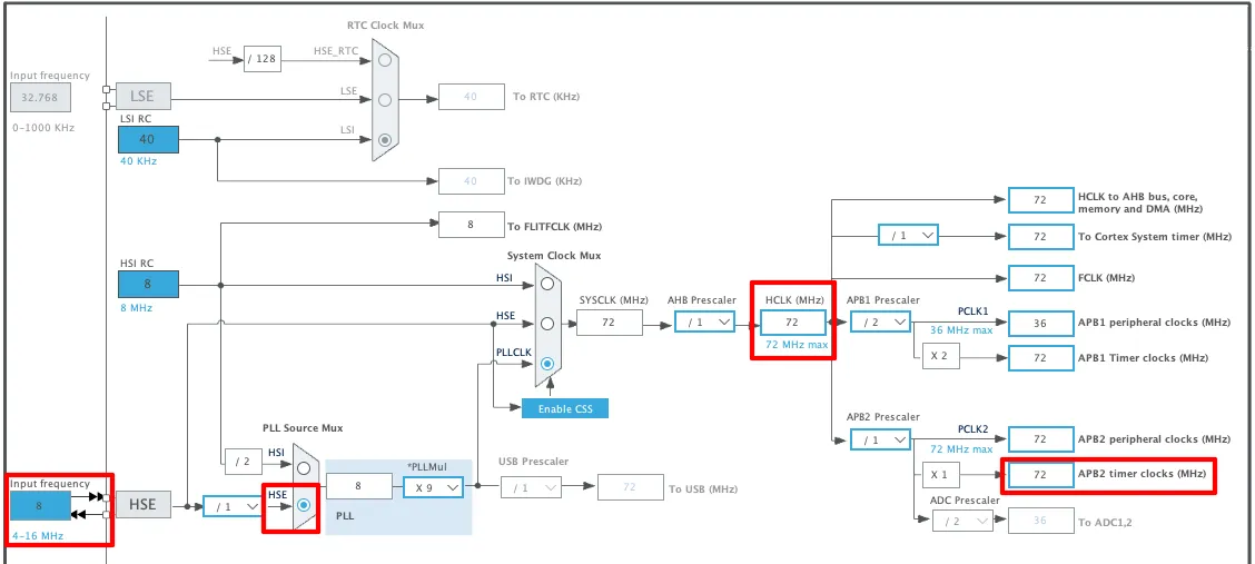
- External Crystal (8MHz) is used to provide the clock via the PLL and the system is running at maximum 72MHz clock.
- I am going to use the TIM1 for the PWM, which is connected to the APB2 Bus.
- The APB2 Timer clock is at 72MHz right now and that makes TIM1 clock = 72MHz.
STM32 PWM Timer Configuration
I am going to use the Timer 1 to generate the PWM signal. The Timer1 PWM configuration is shown in the image below.
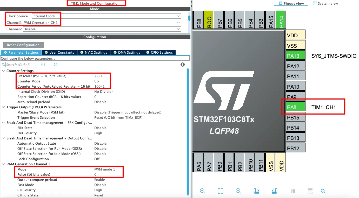
The detailed description of the image is mentioned below.
Timer Setting
- Clock Source: Internal Clock
This sets the timer to use the internal APB2 clock as its source. It’s essential for generating precise time-based signals like PWM without relying on external clocks. - Channel1: PWM Generation CH1
This enables PWM output on Channel 1 of TIM1. It’s what makes the timer output a PWM signal rather than just counting.
Counter Settings
- Prescaler (PSC = 72-1)
This divides the timer’s input clock frequency by 72.
For example, if the APB clock is 72 MHz, the timer counts at 1 MHz after prescaling. - Counter Mode: Up
The timer counts from 0 up to the value in the Auto Reload Register (ARR), then resets and starts over. This is the typical mode for PWM. - Counter Period (ARR = 100-1)
Sets the maximum count value (100 – 1 = 99), which defines the PWM frequency in combination with the prescaler. - For 72 MHz APB clock:

Note:
Calculate the ARR and CCR values for the STM32F4 Timers using the STM32F4 PWM Tool:
https://controllerstech.com/tools/stm32f4-pwm-calculator/
PWM Generation Channel 1 Settings
- Mode: PWM mode 1
This sets the PWM output to PWM Mode 1, which means:- Output is HIGH when the counter is less than the pulse value.
- Output is LOW when the counter is greater than or equal to the pulse value.
- Pulse (CCR1) = 0
This defines the initial duty cycle -> in this case, it’s 0, meaning no ON time.
The output will stay LOW until this value is changed in code.
Pin Mapping (PA8 – TIM1_CH1)
- PA8 (TIM1_CH1)
This is the GPIO pin where the PWM signal will appear.
It is automatically configured as an alternate function output for TIM1 Channel 1. You can connect an LED, motor driver, or other device to this pin to control it with PWM.
PWM DMA Configuration
The image below shows the CubeMX Configuration for the STM32 PWM DMA Mode.
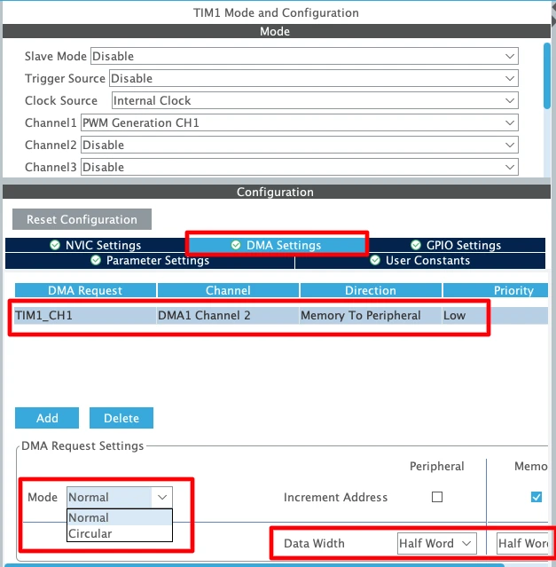
You can choose any DMA stream that is available for the specific Timer channel you are using. The important point here is to configure the DMA direction as Memory to Peripheral, because the PWM duty cycle (pulse width values) will be fetched from memory and written into the Timer’s Capture/Compare register (CCR).
For the data width, I selected Half Word (16-bit, uint16_t). This is because the Timer registers (such as CCR1, CCR2, etc.) are 16-bit wide on most STM32 devices. If your pulse width values fit within 16 bits, using Half Word is the most efficient choice.
PWM DMA Modes
Now, let’s talk about Normal and Circular mode:
- Normal Mode:
In this mode, DMA transfers the data from memory to the Timer only once. For example, if you have an array of pulse widths stored in memory, DMA will move them one by one to the Timer CCR, and after the last value is sent, the transfer stops.- Best suited for one-time waveform generation, like sending a predefined burst of pulses.
- After completion, if you want to generate more waveforms, you need to restart the DMA manually.
- Circular Mode:
In this mode, once DMA finishes transferring all values from the memory buffer, it automatically loops back and starts again from the beginning. This process continues endlessly until you stop it.- Ideal for continuous waveform generation, such as creating repetitive PWM patterns (sine wave, triangular wave, etc.).
- Since the CPU doesn’t need to restart the transfer, it reduces processor overhead and ensures smooth, uninterrupted PWM output.
We will see both the modes, but I will start with Normal Mode first.
Why do we need to use -1 ?
In STM32 timers, the Prescaler (PSC) and Auto-Reload Register (ARR) work in a way that they automatically add +1 to the value you enter. This means if you write a value of PSC = 71, the timer actually divides the clock by 72. Similarly, if you set ARR = 999, the counter counts up to 1000.
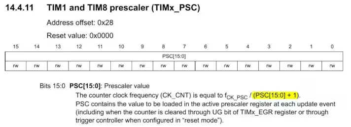
That’s why, when calculating values for frequency or period, we subtract 1 in the formula to match the hardware behavior.
Writing Code for PWM with HAL (Without DMA)
The STM32 HAL library makes it easier to configure and control PWM signals without dealing directly with low-level registers. Let’s break down the process step by step.
Initializing the Timer
First, initialize the timer for PWM mode. When you generate code from STM32CubeMX, it automatically creates initialization functions such as MX_TIMx_Init(). This function sets the prescaler (PSC), auto-reload register (ARR), and configures the timer in PWM mode.
In addition, CubeMX configures the GPIO pin linked to your timer channel in Alternate Function mode, so that the PWM signal can appear on the physical pin.
Starting PWM Output
After initialization, start the PWM output using the HAL function:
HAL_TIM_PWM_Start(&htim1, TIM_CHANNEL_1);Here:
htim1is the timer handle generated by CubeMX.TIM_CHANNEL_1selects the PWM channel (Channel 1 in this case).
You can repeat the same function with TIM_CHANNEL_2, TIM_CHANNEL_3, or TIM_CHANNEL_4 if your timer supports multiple channels.
Changing Duty Cycle in Code
To change the duty cycle at runtime, update the Capture/Compare Register (CCR). For example:
TIM1->CCR1 = 30; // Set duty cycle value <= ARR- The value written to
CCR1controls the ON-time of the signal. - A higher CCR value means a longer pulse (higher duty cycle).
- A smaller CCR value means a shorter pulse (lower duty cycle).
The duty cycle is calculated using the formula:

This method allows you to dynamically adjust brightness of an LED, speed of a motor, or any other load connected to the PWM pin.
Complete Timer PWM Code
You can refer to the main function below to change the duty cycle at the Runtime.
int main(void)
{
  HAL_Init();
  SystemClock_Config();  // System clock setup
  MX_GPIO_Init();        // GPIO init
  MX_TIM1_Init();        // Timer1 init with PWM

  HAL_TIM_PWM_Start(&htim1, TIM_CHANNEL_1);
  while (1)
  {
    /* Example: Update duty cycle dynamically */
    for (int duty = 0; duty <= 99; duty += 10)
    {
      __HAL_TIM_SET_COMPARE(&htim1, TIM_CHANNEL_1, duty);  // TIM1->CCR1 = duty;
      HAL_Delay(500);  // Wait 500ms before changing duty cycle
    }
  }
}The code above gradually changes the PWM duty cycle from 0% to 100%. It increases the duty cycle in 10% steps, and each step occurs every 500 milliseconds.
STM32 PWM Generation Result
The image below show the PWM pulse captured on the Logic Analyser.
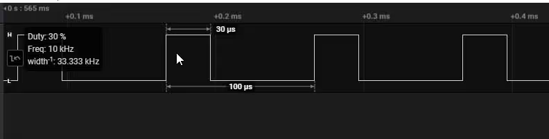
PWM waveform above has the following characteristics:
- Frequency: 10 kHz — each complete cycle lasts 100 microseconds.
- Duty Cycle: 30% — the signal stays HIGH for 30 microseconds and LOW for 70 microseconds in each cycle.
- The waveform clearly displays consistent pulse spacing and width, confirming stable PWM output.
The gif below shows the duty cycle changing every 500ms (press the Play Button). It varies from 0 to 100% in step of 10%.
STM32 PWM DMA Normal Mode Example
In this example, we will learn how to generate PWM signals on an STM32 microcontroller using DMA in Normal Mode. The idea is to preload an array of pulse width values in memory and let DMA transfer these values to the Timer’s Capture/Compare register (CCR). As the transfer happens, the PWM duty cycle changes automatically without CPU intervention.
Since we are using Normal Mode, the DMA will execute the transfer only once. Once the last value from the array is written, the transfer stops, and the PWM output will remain steady at the final duty cycle value.
This approach greatly reduces CPU workload because the duty cycle updates are handled by DMA, while the processor can continue with other tasks.
The main function below demonstrates how to send an array of pulse widths to the DMA.
uint16_t pwmData[11];
int main(void)
{
  HAL_Init();
  SystemClock_Config();
  MX_GPIO_Init();
  MX_DMA_Init();
  MX_TIM1_Init();
//  HAL_TIM_PWM_Start(&htim1, TIM_CHANNEL_1);

  pwmData[0] = 10; pwmData[1] = 20; pwmData[2] = 30;
  pwmData[3] = 40; pwmData[4] = 50; pwmData[5] = 60;
  pwmData[6] = 70; pwmData[7] = 80; pwmData[8] = 90;
  pwmData[9] = 100;pwmData[10] = 0;
  HAL_TIM_PWM_Start_DMA(&htim1, TIM_CHANNEL_1, (uint32_t *)pwmData, 11);
  while(1){
  }
}First, we load the desired duty cycle values into the pwmData array. Since the Timer’s ARR (Auto Reload Register) is set to 100, each value directly represents the duty cycle in percentage. For example, a value of 10 corresponds to 10% duty, 20 to 20% duty, and so on. At the end of the array, we place a 0, which forces the PWM output pin to go LOW once the sequence finishes.
After preparing the array, we call HAL_TIM_PWM_Start_DMA, which transfers all the values to the Timer using DMA. Because the DMA is configured in Normal Mode, it sends the 11 values only once. When the transfer completes, the PWM output stays fixed at the final duty cycle value (0).
Result of PWM DMA Normal Mode
The image below shows the Complete PWM wave on the Logic Analyzer.
You can see that we only get a single PWM Wave with varying Duty cycles. The PWM frequency is fixed at 10KHz, same as what we configured in the CubeMX.
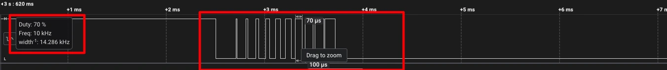
The image below shows the Duty cycles of the PWM waveform.
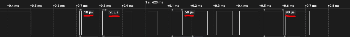
We get the Duty cycle ranging from 10%(1-us) to 100% (visually we can’t show it).
STM32 PWM DMA Circular Mode Example
In this example, we will learn how to generate PWM signals on an STM32 microcontroller using DMA in Circular Mode. Similar to Normal Mode, we preload an array of pulse width values in memory and let DMA transfer these values to the Timer’s Capture/Compare register (CCR). As the transfer happens, the PWM duty cycle changes automatically without CPU involvement.
The difference here is that in Circular Mode, once DMA finishes sending all the values in the array, it automatically starts again from the beginning. This creates a continuous loop of duty cycle updates, making it ideal for generating repetitive waveforms such as sine waves, triangular waves, or any custom pattern.
This method allows the PWM output to run indefinitely with changing duty cycles, while keeping the CPU free for other tasks. The processor does not need to restart the DMA transfer, which ensures smooth and uninterrupted waveform generation.
In order to use the DMA in circular mode, we must configure it in CubeMX as shown in the DMA Configuration Image.
The main function below demonstrates how to send an array of pulse widths to the DMA in Circular Mode.
uint16_t pwmData[13];
int main(void)
{
  HAL_Init();
  SystemClock_Config();
  MX_GPIO_Init();
  MX_DMA_Init();
  MX_TIM1_Init();
//  HAL_TIM_PWM_Start(&htim1, TIM_CHANNEL_1);

  pwmData[0] = 10; pwmData[1] = 20; pwmData[2] = 30;
  pwmData[3] = 40; pwmData[4] = 50; pwmData[5] = 60;
  pwmData[6] = 70; pwmData[7] = 80; pwmData[8] = 90;
  pwmData[9] = 100;pwmData[10] = 0; pwmData[11] = 0;
  pwmData[12] = 0;
  HAL_TIM_PWM_Start_DMA(&htim1, TIM_CHANNEL_1, (uint32_t *)pwmData, 13);
  while(1){
  }
}First, we load the desired duty cycle values into the pwmData array. For example, a value of 10 corresponds to 10% duty, 20 to 20% duty, and so on. At the end of the array, we place three 0, which forces the PWM output pin to stay LOW once the sequence finishes. This will help us distinguish between successive waveforms.
Once the array is ready, we call HAL_TIM_PWM_Start_DMA, which begins transferring the values to the Timer via DMA. Because the DMA is set to Circular Mode, all 13 values are sent in a loop continuously, without requiring any intervention from the CPU.
Result of PWM DMA Normal Mode
The image below shows the Complete PWM waves on the Logic Analyzer.
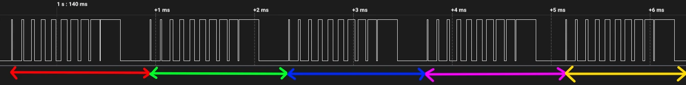
As shown in the image, Circular DMA generates a continuous series of PWM waveforms. The duty cycle in each waveform gradually increases from 10% to 100%, and at the end, the output stays LOW for a short duration due to the three 0 values we added at the end of the array.
How to Stop PWM Circular DMA
When the DMA finishes transferring all values from the array, it triggers an interrupt, which calls the PWM_PulseFinishedCallback function. Inside this callback, you can write custom code—for example, to stop the DMA from sending any further values or to perform other actions once the PWM sequence completes.
int count = 0;

void HAL_TIM_PWM_PulseFinishedCallback(TIM_HandleTypeDef *htim){
	count++;
	if (count == 3){
		HAL_TIM_PWM_Stop_DMA(htim, TIM_CHANNEL_1);
	}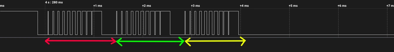
}A counter count tracks how many times the PWM sequence completes. Each time the HAL_TIM_PWM_PulseFinishedCallback is called, the counter increments. When it reaches 3, HAL_TIM_PWM_Stop_DMA stops the DMA on Timer Channel 1, allowing the PWM to run three full cycles before stopping automatically.
The image below shows the circular PWM being stopped after 3 cycles.
To explore a more practical and application-specific example of Circular DMA mode, check out STM32 PWM using DMA. This tutorial provides detailed steps, code examples, and waveform explanations that show how DMA can be used to generate efficient and continuous PWM signals on STM32 microcontrollers.
Video Tutorial
STM32 PWM Tutorial Video
This tutorial demonstrates how to configure and generate PWM on STM32 using CubeMX and HAL. You’ll learn how to calculate timer settings, set up the PWM channels, start the signal, and adjust duty cycles step by step. To make it easier to follow, a video walkthrough is included showing the full process in action. Follow the written guide alongside the video for a complete understanding.
Watch the VideoApplications of PWM in STM32
LED Dimming
PWM allows precise control over LED brightness by adjusting the duty cycle. This technique is widely used in lighting systems and displays to achieve energy-efficient illumination.
Motor Control
By varying the duty cycle, PWM enables control over motor speed and torque. This is essential in applications like robotics, fans, and servo motors, where precise motion control is required.
Communication Protocols
PWM can be utilized in communication systems to encode data. By modulating the pulse width, information can be transmitted between devices, making it useful in various signaling applications.
Troubleshooting PWM Issues
Incorrect Frequency Output
Ensure that the timer’s prescaler and auto-reload register (ARR) are correctly configured to achieve the desired frequency. Double-check the system clock settings in STM32CubeMX to confirm that the timer is receiving the correct clock source.
Duty Cycle Not Updating
If changes to the duty cycle aren’t reflected in the output, verify that the compare register (CCR) is being updated correctly. Additionally, ensure that the timer is running and not in a stopped state.
Pin or Channel Mismatch
Confirm that the PWM output pin is correctly mapped to the timer channel in STM32CubeMX. Mismatches between the configured pin and the actual hardware connection can lead to no output signal.
Conclusion
This tutorial successfully demonstrates how to generate a PWM signal using an STM32 microcontroller. We learned how to configure timers in STM32CubeMX, start PWM output using HAL functions, and adjust the duty cycle to observe changes in the waveform. You can apply this knowledge to practical applications such as dimming LEDs, controlling motor speed, or generating analog-style signals.
In the next tutorials, we will explore advanced topics like PWM input measurement, using DMA with PWM, and generating three-phase PWM signals for motor control. These lessons will help you take your STM32 projects to the next level.
Checkout More STM32 Timer Tutorials
STM32 Timers (Part 3): How to use the Timer Encoder Mode
STM32 Timers (Part 4): Input Capture Tutorial | Measure Frequency & Pulse Width
STM32 Timers (Part 5): STM32 Timer Synchronization Using Slave Trigger Mode
STM32 Timers (Part 6): Timer Synchronization for 3-Phase PWM Generation
STM32 Timers (Part 7): Timer synchronization using Slave Reset mode
STM32 Timers (Part 8): How to Create a 48-Bit Counter by Cascading Timers

hello
im usin stm32f407vet6 to control bldc motor for my graduation project
idk whats the teacher sayin about the frequency must be 5kHz he said use only PWM and dont use the adc the sys frequency is 84MHz
can u plz help in configuring the card also help on codin !
This article explains the exact thing, how to generate PWM with some fixed frequency. Please read it, or watch the video.
Para que utilizas interrupciones! solo quiero enviar una señal pwm solo eso. You code while is empty not interrpt
Where did I used interrupt ?
Great example! Worked fine for me for anyone who can’t get it working
1) Make sure PWM Timer is enabled.
2) Make sure CCR value is correct.
3) Double check Timer clock settings.
Thanks for your tutorial.
I switched from Microchip to STM32 and everything is a little bit different^^
I use the Board Nucleo G474RE and got the PWM-Output working. So I wanted to use more outputs with the same PWM-Timer and set the CCR for Channel 2, 3 and 4 of TIM1.
Unfortunately I get only an output on channel 1.
I tried this:
HAL_TIM_PWM_Start(&htim1, TIM_CHANNEL_1 | TIM_CHANNEL_2 | TIM_CHANNEL_3 | TIM_CHANNEL_4);
this:
HAL_TIM_PWM_Start(&htim1, TIM_CHANNEL_1);
HAL_TIM_PWM_Start(&htim1, TIM_CHANNEL_2);
HAL_TIM_PWM_Start(&htim1, TIM_CHANNEL_3);
HAL_TIM_PWM_Start(&htim1, TIM_CHANNEL_4);
and this: //makes no sense for me…
HAL_TIM_PWM_Start(&htim1, TIM_CHANNEL_1 & TIM_CHANNEL_2 & TIM_CHANNEL_3 & TIM_CHANNEL_4);
with the CCR-Settings:
TIM1->CCR1 = 120; // PWM OUTPUT is on PIN A5 (PC0)
TIM1->CCR2 = 120; // PWM OUTPUT is on PIN A4 (PC1)
TIM1->CCR3 = 120; // PWM OUTPUT is on opposite Pin of A5 (PC2)
TIM1->CCR4 = 120; // PWM OUTPUT is on opposite Pin of A4 (PC3)
best regards
Yeah, I got it running.
Unfortunately I selected “Output Compare CHx” instead of “PWM Generation CHx”.
I want to see how you wire up the complete circuit and what are the necessary links
Hi I want to use example but with an interrupt, can I modify CCRx while using interrupt? if not I can just use the example as is. But will I get accurate timing with the cpu running other parts of the code if I don’t use interrupt?
Hi I want to use example but with an interrupt? can I modify CCRx while using interrupt? if not I can just use the example as is. But will I get accurate timing with the cpu running other parts of the code if I don’t use interrupt?
I used the same configuration, but the last example didnt work either. There is no signal output at TIM_CH1. The others worked as expected.
I use STM32F410RB board.
There is nothing in this example, so “not working” is not possible.
Check your CCR value, also if you have started the timer in PWM mode.
Also make sure you are measuring the output from the right pin.
You are the best! Thanks for all of your work.
I am using the STM32F401RE with the same code and same configuration, I confirmed the oscillator is 8Mhz and check that TIM1 is on APB1 – when I connect my logic analyzer I see nothing, no PWM signal.
is there something I can check to figure out what I am missing ?
2 things.
Thanks, I fixed the problem – another question, to bring the frequency to 100 kHz, the ARR to 10 instead of 100 ?
yes
That works like a charm !
I am running a Nucleo-64 with a STM32F401RE on it and the PWM frequency, as clocked by APB1, is nothing compared to what it should be. Say APB1 clock frequency is 84MHz and the pre-scale is 20 I get 19.84MHz on the PWM output?
In the clock setup make sure that input frequency is 8 MHz and not 25 MHz
How to generate a center aligned pwm.
Because the PWM is a periodic signal it is center aligned.
But it is easier to to read the time if you don’t view it as center aligned.