Home ▸ ESP32 ▸ FreeRTOS Tutorials ▸
Updated On: April 26, 2026
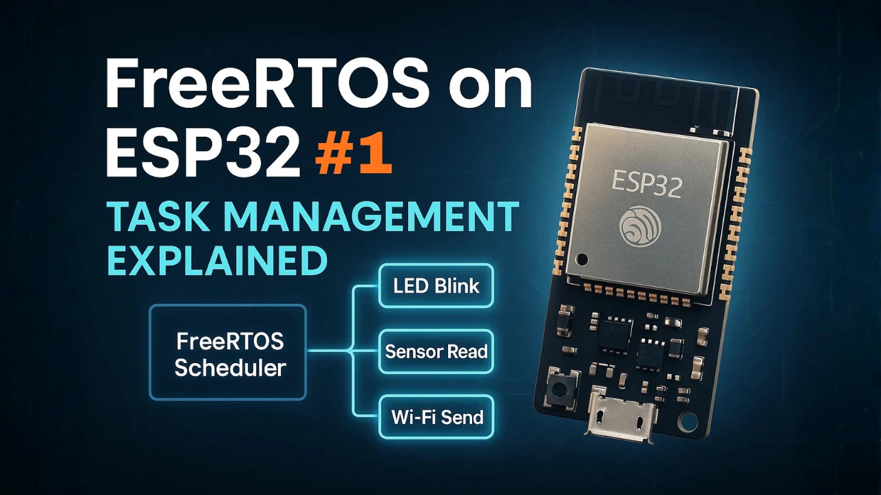
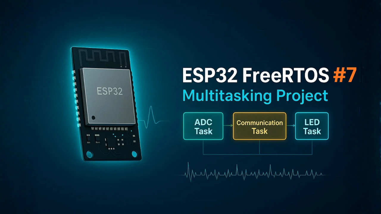
ESP32 FreeRTOS Multitasking Project: ADC Sensor, Communication and LED Tasks
The previous six tutorials each covered one FreeRTOS concept in isolation. This tutorial puts them all together in one project that does real work: reads analog sensor data with the ADC, passes it to a communication task via queue, transmits it over UART, and uses an LED task as a live system status indicator driven by task notifications. Three tasks, running concurrently, using queues, notifications, and a software timer for periodic ADC triggering.
This is Part 7 — the final tutorial in the ESP32 FreeRTOS Series. Use it as a template for your own sensor, IoT, or data logging applications. The architecture scales: add more tasks, swap UART for Wi-Fi, or replace the ADC sensor with I²C or SPI without restructuring the core design.
This is Part 7 of the ESP32 FreeRTOS Series using ESP-IDF. You can check the other parts as well, here are the links:
- Part 1 — Intro to FreeRTOS: Tasks, Scheduler & xTaskCreate
- Part 2 — Understanding the FreeRTOS Scheduler
- Part 3 — Task Priority & Stack Management
- Part 4 — Inter-Task Communication: Queues, Semaphores & Event Groups
- Part 5 — Software Timers & Task Notifications
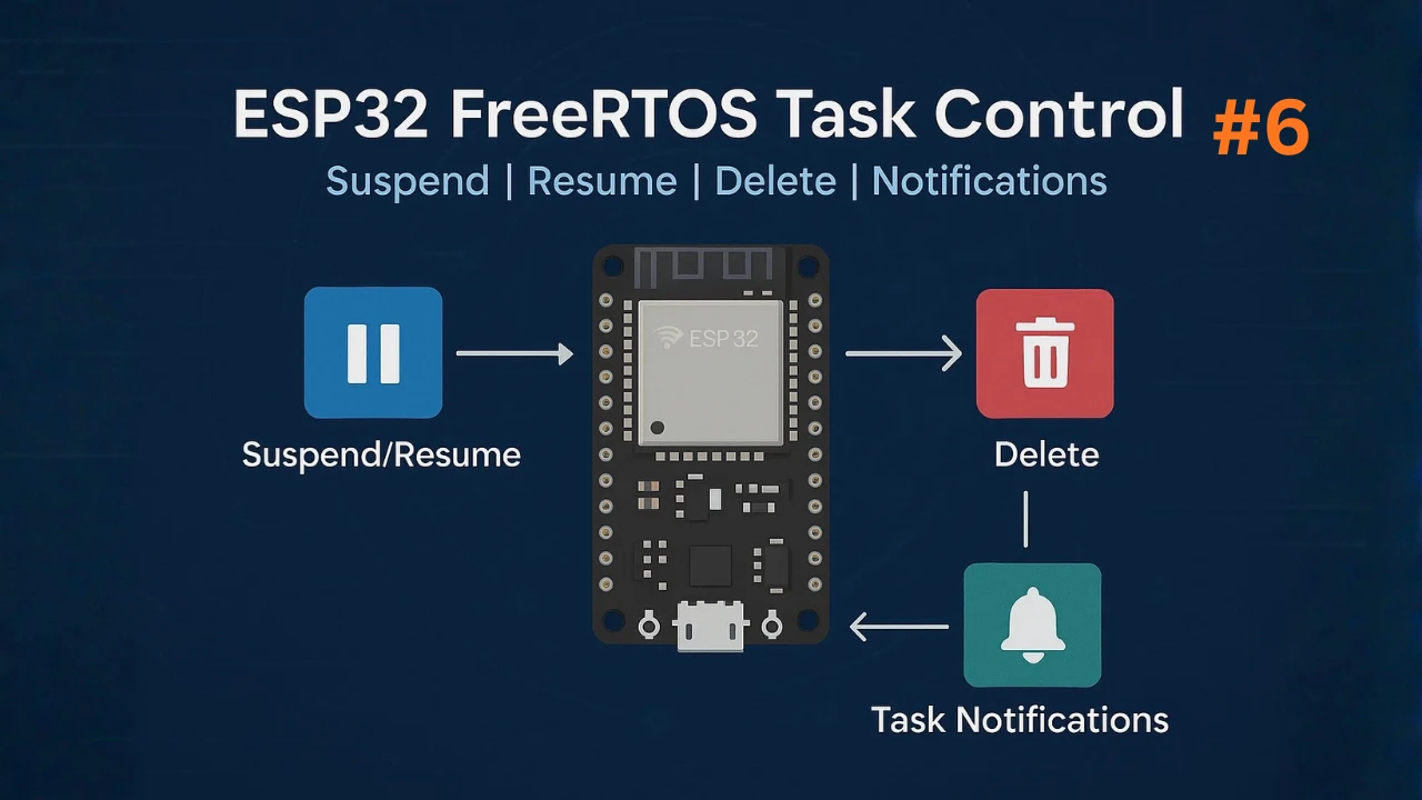
- Part 6 — Task Control: Suspend, Resume & Delete
- Part 7 — Real-Time Multitasking Project (ADC, UART, LED) ← you are here
Project Overview: What We’re Building
In this project, we will build a complete real-time multitasking system using ESP32 FreeRTOS. The idea is simple, but powerful. We will create three separate tasks, and each task will handle one important job. All tasks will run at the same time, without blocking each other. This will give you hands-on experience with real-time scheduling, inter-task communication, and practical embedded design.
This project is a perfect way to apply everything you learned in the previous FreeRTOS tutorials.
Three Tasks: ADC Sensor, Communication, LED Indicator
In this real-time example, we will create three independent tasks:
- ADC Sensor Task
This task reads an analog sensor using the ESP32 ADC. The reading is periodic, and the value is sent to another task using a FreeRTOS queue. - Communication Task (UART / Wi-Fi)
This task receives sensor data from the queue and sends it out. You can choose UART for debugging or Wi-Fi for IoT applications. It only runs when new data is ready. - LED Indicator Task
This task updates an LED based on the system status. It can blink on data send, warn on errors, or show activity. The LED task uses FreeRTOS notifications to react instantly.
Together, these tasks form a practical multitasking system.
Why Use FreeRTOS for This Use Case
FreeRTOS is ideal when you have multiple jobs that must run independently. Without an RTOS, you would block the CPU with delays and polling, which makes the system slow and unreliable.
But with FreeRTOS:
- Each job becomes a separate task.
- Tasks do not block each other.
- Sensor reading, sending data, and LED status run smoothly in parallel.
- Timing becomes predictable.
- The project becomes easier to scale.
This is exactly why FreeRTOS is widely used in IoT devices, industrial systems, and any project where timing matters.
FreeRTOS Features Used in This Project
This project uses almost every important FreeRTOS feature you learned so far:
- Tasks
Three tasks run independently for ADC sampling, communication, and LED updates. - Queues
The sensor task sends data to the communication task using a queue. This is a clean and safe way to pass data. - Task Notifications
The LED task gets notified when an event happens (for example, when data is sent). - Software Timers
A periodic timer triggers the ADC sampling without blocking any task.
These features combine to create a stable, responsive, and real-time system. This is the kind of architecture used in professional embedded products.
Required Hardware Setup
Before we start building the multitasking system, let’s set up the hardware. The setup is simple, and you can use any analog sensor of your choice. We will read the sensor using the ESP32’s built-in ADC, send the data to another task, and then update an LED based on system activity.
Hardware Components (ESP32, Sensor, LED, etc.)
You will need only a few components to follow this project:
- ESP32 Development Board (ESP32-DevKitC or similar)
- Analog Sensor (Potentiometer, LM35, LDR with voltage divider, or any sensor with analog output)
- LED (any color)
- 220Ω resistor for the LED
- Jumper wires
- Breadboard (optional but helpful)
The sensor will be connected to one of the ADC pins. The LED will connect to a GPIO pin.
Circuit Diagram & ADC Connections
The ADC hardware in ESP32 supports various modes of operation such as one-shot mode, continuous mode, and DMA mode (on newer chips), making it suitable for both low-latency and high-throughput applications.
Below is the image showing the ADC channels on the ESP32 dev board.
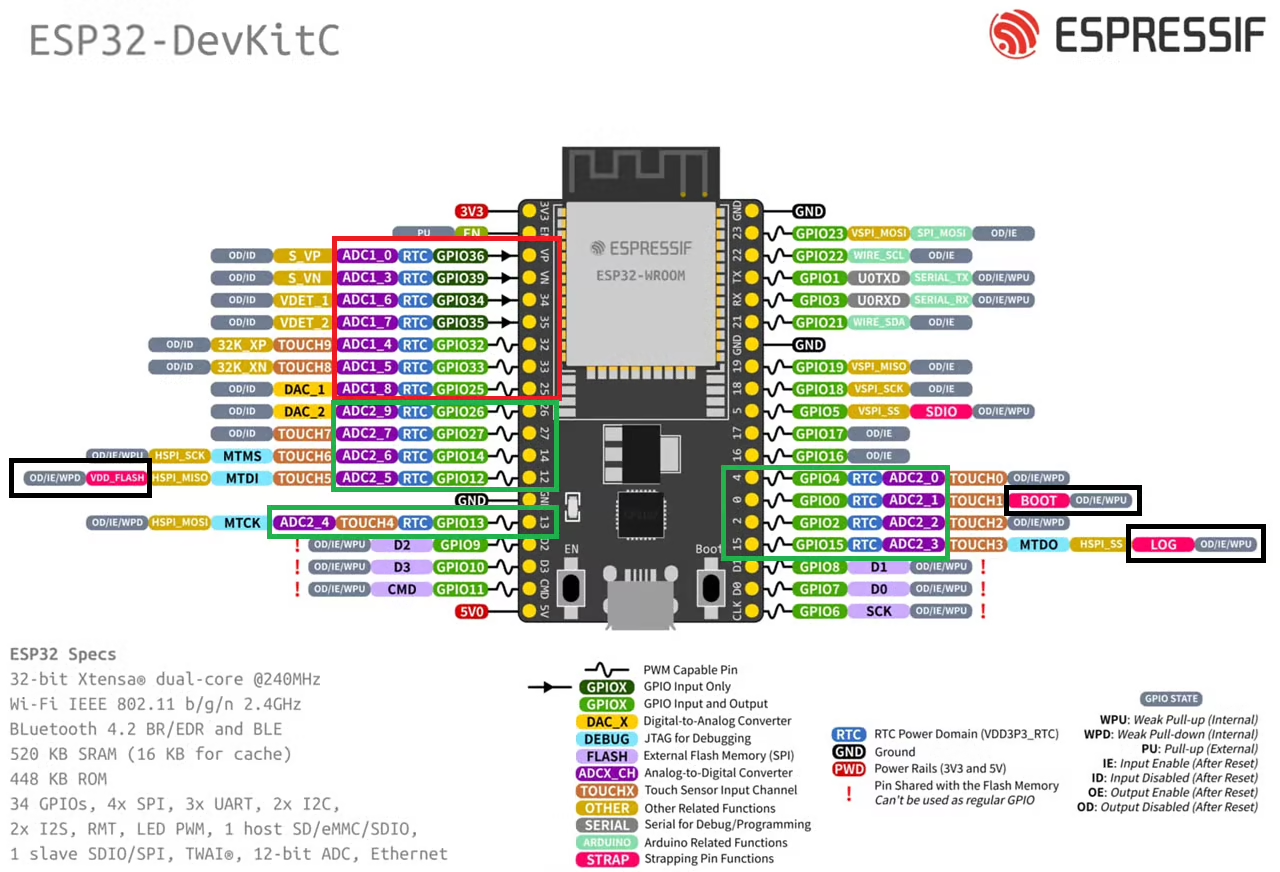
The Red box in the image above highlights the ADC1 channels, whereas the Green box highlights the ADC2 channels. We can use either of these ADC units. Just try to avoid the pins highlighted with Black box. These are the strapping pins which are used during flashing the chip. Therefore in order to use these pins for some other purpose, they require additional configuration.
The ESP32 has multiple ADC channels on GPIO 32–39 (ADC1) and GPIO 0, 2, 4, 12–15, 25–27 (ADC2). To avoid Wi-Fi conflicts, it is strongly recommended to use ADC1.
In this tutorial, we will use:
- GPIO 34 (ADC1 Channel 6) as the analog input
- GPIO 2 for LED output
The image below shows the connection between ESP32, Potentiometer and the LED.
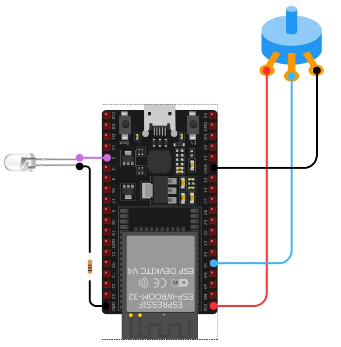
Below is the connection table:
| Component | ESP32 Pin | Description |
|---|---|---|
| Analog Sensor Output | GPIO 34 (ADC1_CH6) | Reads the analog voltage |
| Sensor VCC | 3.3V | Powers the sensor |
| Sensor GND | GND | Common ground |
| LED + (Anode) | GPIO 2 | LED indicator output |
| LED – (Cathode) | GND via 220Ω resistor | Current limiting |
The circuit is simple, and any analog sensor with a 0–3.3V output will work with this ADC setup.
Task Architecture & Inter-Task Communication
Task Design and Data Flow Diagram
In this section, we will break down the design of all three tasks. Each task performs a dedicated job, and all tasks run in parallel under FreeRTOS. This clean separation makes the system easier to manage, debug, and scale.
To keep the timing accurate and responsive, we will also use a FreeRTOS Software Timer for periodic ADC sampling. The tasks will communicate through queues and notifications, just like we practiced in earlier tutorials.
To help you understand the overall flow of this real-time project, the image below shows how all three FreeRTOS tasks work together on the ESP32. The diagram highlights the ADC sampling task, the communication task, and the LED indicator task, along with the queue, software timer, and notification signals connecting them.
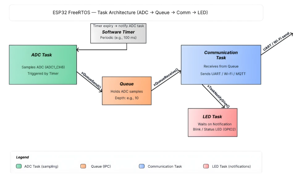
Let’s look at each task in detail.
Task 1: ADC Sensor Reading via FreeRTOS Timer
The first task focuses on reading analog data from the ADC. Instead of using vTaskDelay, we will use a FreeRTOS software timer to trigger ADC sampling at a fixed interval.
How it works:
- A software timer (for example, 100 ms period) fires periodically.
- The timer callback reads the sensor value from the ADC.
- The ADC value is sent to the communication task using a queue.
- Since the timer runs independently, the ADC task never blocks other tasks.
This design keeps the ADC timing stable and ensures the system remains fully responsive.
Advantages:
- Precise timing for sensor sampling
- No delays inside tasks
- ADC reading stays consistent even under heavy CPU load
Task 2: Communication (UART or Wi-Fi)
The second task handles sending the sensor data out. You can choose between:
- UART, which is simpler and great for debugging, or
- Wi-Fi, which enables sending sensor readings to a server, MQTT broker, or dashboard.
How this task works:
- It waits for new ADC data from the queue.
- As soon as data arrives, the task wakes up.
- It prints the value over UART or sends it through Wi-Fi.
- After sending the data, it notifies the LED task.
This task consumes data only when available, so it does not waste CPU cycles.
Typical use cases:
- Serial monitoring
- IoT telemetry updates
- Sending values to a mobile app or cloud service
Task 3: LED Indicator Task
The LED task is simple but very important for debugging and user feedback. This task receives notifications from the communication task.
LED behaviors may include:
- Blink once when new data is sent
- Fast blinking for errors
- Solid ON when system is active
- OFF for idle state
How it works:
- The task blocks on
ulTaskNotifyTake(). - It wakes up only when an event occurs.
- The LED toggles or changes state depending on the notification.
This design makes the LED task extremely lightweight.
Task Priority and Stack Size Strategy
Choosing the right priorities and stack sizes is crucial for a stable FreeRTOS system. Here is the recommended approach:
1. ADC Timer Callback / ADC Task
- Priority: Medium
- Reason: Sensor sampling must be consistent, but not more critical than communication.
2. Communication Task (UART/Wi-Fi)
- Priority: Higher
- Reason: Data transfer should be quick to avoid queue backups.
In Wi-Fi mode, communication needs higher priority to keep up with network timing.
3. LED Task
- Priority: Low
- Reason: Status indication is not time-critical.
Stack Size Recommendations
These vary based on your code complexity:
| Task | Suggested Stack Size |
|---|---|
| ADC Reading / Timer Handler | 2048 bytes |
| Communication Task | 4096 bytes (more if Wi-Fi is used) |
| LED Task | 1024 bytes |
This balanced structure ensures smooth, stable multitasking without starving any task.
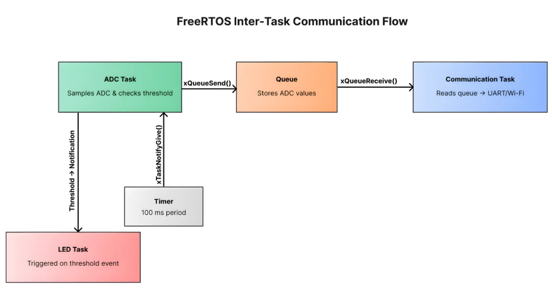
Queue: ADC Task → Communication Task
To make multiple tasks work together, we need a clean and reliable way to exchange data. FreeRTOS gives us several tools for this, such as queues, notifications, mutexes, and semaphores. In this project, the ADC task, communication task, and LED task interact through these FreeRTOS features.
The diagram below shows how data moves inside this project. The ADC Task sends sensor values into a queue. The Communication Task receives those values and prints or transmits them. A software timer triggers the ADC Task using notifications. And when the ADC value crosses a threshold, the LED Task gets a notification to update the indicator.
Using FreeRTOS Queues for ADC Data
Queues are the safest and most common method to pass data between tasks in FreeRTOS. They handle synchronization automatically and prevent data corruption.
How we use the queue in this project:
- The software timer or ADC task reads the sensor value.
- It sends the ADC reading (for example, a 16-bit or 32-bit integer) into a queue.
- The communication task waits on that queue using
xQueueReceive(). - As soon as a new value appears, the communication task wakes up and sends it through UART/Wi-Fi.
This design ensures that:
- No data is lost
- No busy-waiting happens
- The communication task runs only when new data arrives
- The ADC sampling stays periodic and predictable
Queue size recommendation:
A queue with 5–10 entries is more than enough, since data is consumed quickly.
Task Notifications to Signal When Data Is Ready
While queues handle the data transfer, task notifications are perfect for simple event signaling.
In this project, task notifications are used to trigger the LED task.
Flow:
- Communication task finishes sending the ADC value
- It sends a notification to the LED task using
xTaskNotifyGive() - LED task waits using
ulTaskNotifyTake() - When notified, the LED toggles or blinks
Why use notifications here?
- They are faster than queues
- Zero RAM overhead
- Great for one-way signaling
- Perfect for small event messages such as “blink LED now”
This makes the LED task extremely lightweight and responsive.
(Optional) Mutex or Semaphore if Shared Buffers Are Used
A mutex or semaphore is only needed if:
- Two tasks access the same global buffer
- You use a shared UART/Wi-Fi buffer
- You add file writing or shared peripherals later in the project
For the basic ADC -> Queue -> Communication -> LED pattern, a mutex is not required.
But if you expand the project later:
- Use a mutex to protect shared memory
- Use a binary semaphore when one task should wait for a hardware event
- Use a counting semaphore for repeated events
Example:
If both ADC and communication tasks write to the same data array, a mutex must protect the buffer to avoid corrupted data.
Timer & Notification: Triggering the ADC Task
FreeRTOS software timers help you schedule events without blocking any task. They let you run code at fixed intervals, even when the CPU is busy with other tasks. In this project, we use a timer to trigger ADC sampling and then use task notifications to wake the communication and LED tasks at the right moment.
This approach keeps the system accurate, responsive, and fully non-blocking.
The timeline below shows how the timer triggers at fixed intervals, wakes the ADC task using notifications, and then passes that event forward to other tasks.

Creating a Software Timer for Periodic ADC Reads
The periodic ADC sampling is handled by a FreeRTOS software timer. Instead of putting delays inside a task, the timer runs independently and calls a callback function on every expiry.
How it works:
- Create the timer using
xTimerCreate(). - Set the period (for example, 100 ms).
- Start the timer in
app_main(). - When the timer expires, the callback executes immediately.
- The callback reads the ADC value and pushes it into the queue.
Why this is better than vTaskDelay:
- More accurate timing
- No blocking inside tasks
- All tasks remain responsive
- Timer runs even when tasks are suspended
- CPU usage stays low
The timer ensures the ADC value is sampled at a fixed interval, giving you stable sensor readings.
Notifying the Communication Task on Timer Expiry
Once the ADC value is pushed into the queue, the communication task must wake up to send it out. Queues already wake the communication task automatically when data arrives, but you may also send a notification if you want additional control.
Typical flow:
- Timer callback reads ADC
- ADC value is sent to queue
- Communication task wakes up using
xQueueReceive() - After sending the data, it can notify the LED task
The communication task stays blocked until data is available.
This means:
- No wasted CPU time
- Zero polling
- Event-driven behavior
- Clean synchronization
This makes the communication task efficient and fast.
Using Notifications to Wake the LED Task Based on Events
The LED task reflects system activity. It does not run continuously. Instead, it waits for a notification from the communication task.
Flow:
- Communication task finishes sending the ADC data
- It calls
xTaskNotifyGive(led_task_handle); - LED task waits using
ulTaskNotifyTake(pdTRUE, portMAX_DELAY); - When a notification is received, the LED updates
This design has several advantages:
- LED task uses almost zero CPU time
- It wakes only when needed
- Notifications are extremely fast (no RAM overhead)
- LED behavior is event-driven
You can customize the LED pattern:
- Single blink -> Data sent
- Double blink -> Error
- Fast blink -> High ADC reading
- Solid ON -> System active
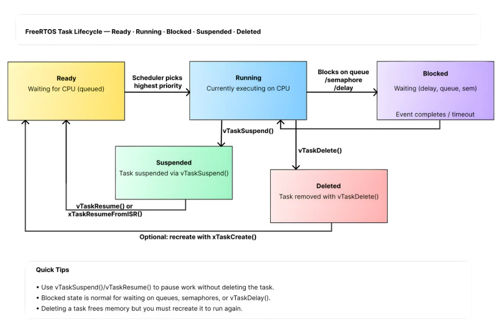
Task Lifecycle and Fault Handling
FreeRTOS gives you full control over how tasks behave during the lifetime of your application. You can suspend tasks, resume them later, delete them completely, or even restart them when needed. Proper task control also helps you build a stable system that can recover from errors like communication failure, stack overflow, or watchdog resets.
In this section, we will explore how to manage task lifecycle and handle common faults in a real ESP32 FreeRTOS project.
The diagram below visualizes the most important task states, Ready, Running, Blocked, Suspended, and Deleted and the events that cause transitions (scheduling, notifications, delays, suspend/resume, and deletion).
Suspending / Resuming Tasks Dynamically (e.g. if communication fails)
There are moments when a task should stop running temporarily. For example, if the communication task detects that UART or Wi-Fi is not available, there is no point in letting it run and waste CPU cycles.
You can manage this easily using:
vTaskSuspend(task_handle);vTaskResume(task_handle);
Typical use case scenario:
- Communication task tries sending data
- If the Wi-Fi connection drops or UART errors occur
- The task suspends itself using
vTaskSuspend(NULL); - Another task or event (like reconnecting Wi-Fi) resumes it
This pattern helps conserve CPU time and makes your system more predictable.
When to use suspend/resume:
- Handling sensor errors
- Communication link failure
- Waiting for a resource
- Pausing low-priority tasks during heavy processing
Suspending tasks ensures that only the necessary work is executed.
Deleting Tasks When Not Needed (or Restarting)
Sometimes a task only needs to run once or for a limited time.
FreeRTOS allows tasks to be removed permanently using:
vTaskDelete(task_handle);
Example use cases:
- A setup task that only runs during initialization
- A calibration task that finishes after storing values
- A temporary task created for diagnostics
- A communication task that must restart after a fatal error
Restarting a task is simple:
- Delete the task
- Create it again using
xTaskCreate()
This method keeps the system stable and prevents tasks from continuing in a bad state.
Why deleting tasks is useful:
- Frees memory
- Prevents corrupted tasks from running
- Helps recover from unexpected failures
- Keeps the system lean and responsive
This makes your application more resilient and modular.
Handling Stack Overflow, Watchdog & Debugging
Fault handling is one of the most important parts of building a robust FreeRTOS system. ESP32 has built-in protection mechanisms, and knowing how to interpret them will save you hours of debugging.
1. Stack Overflow Handling
If a task uses more stack than allocated, ESP-IDF can detect it and trigger a panic.
You should enable stack overflow checking in menuconfig:
Component config -> FreeRTOS -> Check for stack overflowFreeRTOS supports two methods:
- Method 1: Basic check
- Method 2: More thorough (recommended)
When overflow occurs, you usually see:
***ERROR*** A stack overflow in task <task_name> has been detectedTo avoid this:
- Increase stack size in
xTaskCreate() - Remove large local variables
- Use dynamic memory or static buffers instead
2. Watchdog Timer (WDT)
ESP32 includes a Task Watchdog Timer that resets the chip if any task blocks for too long.
You may see errors like:
Task watchdog got triggered.Common causes:
- Long
while(1)loops without delays - A high-priority task starving others
- Blocking network calls inside a task
- Improper use of mutexes or semaphores
Fixes:
- Always use
vTaskDelay()ortaskYIELD()in loops - Avoid doing heavy work on high-priority tasks
- Break long operations into smaller steps
- Ensure all tasks get CPU time
3. Debugging FreeRTOS Issues
Here are some helpful debugging tips:
- Use
uxTaskGetStackHighWaterMark()to check remaining stack - Use
vTaskList()to print task details (requires enabling trace features) - Check queue sizes to avoid overflows
- Add LED indicators or UART logs for error states
- Use Wi-Fi debug logging for communication issues
These tools make it easier to find bottlenecks or faults in your system.
Code Walkthrough & Live Results
In this part, we will walk through the full code structure. You will see how each task works, how ADC data flows through queues, and how notifications trigger actions.
This section keeps everything simple and easy to follow.
ADC Sensor Task Code
The ADC task waits for the timer callback. When the timer expires, it sends a notification to the ADC task.
The ADC task:
- Waits for a notification.
- Reads ADC value.
- Sends the reading to the queue.
- Notifies the LED task.
Example logic:
void adcTask(void *pv)
{
    int adcValue = 0;

    while (1)
    {
        ulTaskNotifyTake(pdTRUE, portMAX_DELAY);

        adcValue = adc1_get_raw(ADC1_CHANNEL_6);

        xQueueSend(adcDataQueue, &adcValue, 0);

        xTaskNotifyGive(ledTaskHandle);
    }
}This task stays blocked most of the time. It only wakes when the timer tells it to.
UART Communication Task Code
The communication task receives ADC values from the queue.
You may implement this using:
- UART TX
- Wi-Fi (MQTT / HTTP / socket)
- BLE
- ESP-NOW
Basic UART example:
void commTask(void *pv)
{
    int recvValue = 0;

    while (1)
    {
        if (xQueueReceive(adcDataQueue, &recvValue, portMAX_DELAY))
        {
            printf("ADC Value: %d\n", recvValue);
        }
    }
}If Wi-Fi is used, replace the printf() with your network send function. This task also remains blocked until data arrives.
LED Indicator Task Code
The LED task waits for notifications from the ADC task.
Possible LED behavior:
- LED blinks once for every ADC sample.
- LED stays ON when ADC value is high.
- LED toggles for communication success.
Example:
void ledTask(void *pv)
{
    gpio_reset_pin(GPIO_NUM_2);
    gpio_set_direction(GPIO_NUM_2, GPIO_MODE_OUTPUT);

    while (1)
    {
        ulTaskNotifyTake(pdTRUE, portMAX_DELAY);

        gpio_set_level(GPIO_NUM_2, 1);
        vTaskDelay(pdMS_TO_TICKS(100));
        gpio_set_level(GPIO_NUM_2, 0);
    }
}This task consumes almost no CPU time because it sleeps until notified.
Queue & Notification Logic
FreeRTOS queue + notification flow:
1. Timer expires -> ADC task notified
- Timer callback uses
xTaskNotifyGive()
2. ADC task reads ADC -> sends to queue
xQueueSend(adcDataQueue, &adcValue, 0)
3. Communication task receives from queue
xQueueReceive(adcDataQueue, &value, portMAX_DELAY)
4. ADC task notifies LED task
xTaskNotifyGive(ledTaskHandle)
app_main(): Creating Tasks and Queues
app_main() is the entry point.
Here we:
- Initialize the ADC.
- Create the FreeRTOS queue.
- Create the three tasks.
- Create the software timer.
- Start the timer so ADC sampling begins.
Example Structure:
void app_main(void)
{
    adc_init();  // Configure ADC channel and width

    adcDataQueue = xQueueCreate(10, sizeof(int));
    if (adcDataQueue == NULL) {
        printf("Queue creation failed\n");
        return;
    }

    xTaskCreate(adcTask, "ADC Task", 2048, NULL, 5, &adcTaskHandle);
    xTaskCreate(commTask, "Comm Task", 4096, NULL, 4, &commTaskHandle);
    xTaskCreate(ledTask, "LED Task", 1024, NULL, 3, &ledTaskHandle);

    adcTimer = xTimerCreate("ADC Timer",
                            pdMS_TO_TICKS(1000),
                            pdTRUE,
                            NULL,
                            adcTimerCallback);

    xTimerStart(adcTimer, 0);
}The timer triggers every 1 second to start an ADC read. This keeps the sampling periodic and stable.
Complete Code for Multi Tasking
The code below combines all the steps mentioned above.
#include <stdio.h>
#include <stdlib.h>
#include "freertos/FreeRTOS.h"
#include "freertos/task.h"
#include "freertos/queue.h"
#include "freertos/timers.h"
#include "driver/adc.h"
#include "driver/gpio.h"
#include "esp_log.h"
#include "esp_err.h"

// ----- Config -----
#define ADC_GPIO            GPIO_NUM_34      // ADC1_CH6
#define ADC_CHANNEL         ADC1_CHANNEL_6
#define ADC_ATTEN           ADC_ATTEN_DB_12  // For full-scale ~3.3V
#define ADC_WIDTH           ADC_WIDTH_BIT_12

#define LED_GPIO            GPIO_NUM_2

#define ADC_TIMER_PERIOD_MS 1000             // ADC sample every 1000 ms
#define QUEUE_LENGTH        10

// Task stack sizes and priorities
#define STACK_ADC_TASK      2048
#define STACK_COMM_TASK     4096
#define STACK_LED_TASK      2048

#define PRIO_ADC_TASK       5
#define PRIO_COMM_TASK      6   // higher so comm can process quickly
#define PRIO_LED_TASK       3

// ----- Globals -----
static QueueHandle_t adcDataQueue = NULL;
static TaskHandle_t adcTaskHandle  = NULL;
static TaskHandle_t commTaskHandle = NULL;
static TaskHandle_t ledTaskHandle  = NULL;
static TimerHandle_t adcTimer      = NULL;

static const char *TAG = "multitask_demo";

// ----- Prototypes -----
static void adc_init(void);
static void adcTask(void *pvParameters);
static void commTask(void *pvParameters);
static void ledTask(void *pvParameters);
static void adcTimerCallback(TimerHandle_t xTimer);

// ----- Implementation -----

static void adc_init(void)
{
    // Configure ADC1 width and channel attenuation
    ESP_ERROR_CHECK(adc1_config_width(ADC_WIDTH));
    ESP_ERROR_CHECK(adc1_config_channel_atten(ADC_CHANNEL, ADC_ATTEN));
    ESP_LOGI(TAG, "ADC initialized on GPIO %d (ADC1_CH6)", ADC_GPIO);
}

static void adcTimerCallback(TimerHandle_t xTimer)
{
    // Timer service task context - notify ADC task to sample
    if (adcTaskHandle != NULL) {
        BaseType_t xHigherPriorityTaskWoken = pdFALSE;
        // Use xTaskNotifyGiveFromISR if this were a real ISR; timer callback runs in timer service task so normal notify is fine:
        xTaskNotifyGive(adcTaskHandle);
    }
}

static void adcTask(void *pvParameters)
{
    (void) pvParameters;
    int raw = 0;

    while (1) {
        // Wait for notification from timer (blocks indefinitely)
        ulTaskNotifyTake(pdTRUE, portMAX_DELAY);

        // Read ADC raw value
        raw = adc1_get_raw(ADC_CHANNEL);

        // Optionally convert raw to voltage using calibration (not included here).
        // Send raw value to queue (non-blocking; if full, drop oldest or handle as needed)
        if (adcDataQueue != NULL) {
            if (xQueueSend(adcDataQueue, &raw, pdMS_TO_TICKS(10)) != pdPASS) {
                ESP_LOGW(TAG, "ADC queue full. Dropping sample %d", raw);
            }
        }
        // Note: we do not notify LED here. Communication task notifies LED after successful send.
    }
}

static void commTask(void *pvParameters)
{
    (void) pvParameters;
    int recvValue = 0;

    // Example: if using Wi-Fi, initialize it here (omitted). This demo uses UART (printf).
    while (1) {
        // Block until an ADC value is available
        if (xQueueReceive(adcDataQueue, &recvValue, portMAX_DELAY) == pdPASS) {
            // Send over UART (console)
            printf("ADC Value: %d\n", recvValue);
            fflush(stdout);

            // If you want to use Wi-Fi/MQTT, call the send function here instead of printf.
            // Example:
            // if (wifi_send_value(recvValue) == ESP_OK) { ... }

            // Notify LED task about successful send
            if (ledTaskHandle != NULL) {
                xTaskNotifyGive(ledTaskHandle);
            }
        }
    }
}

static void ledTask(void *pvParameters)
{
    (void) pvParameters;

    // Configure LED pin
    gpio_reset_pin(LED_GPIO);
    gpio_set_direction(LED_GPIO, GPIO_MODE_OUTPUT);
    gpio_set_level(LED_GPIO, 0);

    while (1) {
        // Wait indefinitely for a notification (from commTask)
        ulTaskNotifyTake(pdTRUE, portMAX_DELAY);

        // Blink once to indicate data sent
        gpio_set_level(LED_GPIO, 1);
        vTaskDelay(pdMS_TO_TICKS(100));   // LED on for 100 ms
        gpio_set_level(LED_GPIO, 0);
    }
}

void app_main(void)
{
    ESP_LOGI(TAG, "Starting ESP32 FreeRTOS Multitasking Example");

    // Initialize ADC
    adc_init();

    // Create queue for ADC data
    adcDataQueue = xQueueCreate(QUEUE_LENGTH, sizeof(int));
    if (adcDataQueue == NULL) {
        ESP_LOGE(TAG, "Failed to create ADC queue");
        return;
    }

    // Create tasks
    BaseType_t ret;

    ret = xTaskCreate(adcTask, "ADC_Task", STACK_ADC_TASK, NULL, PRIO_ADC_TASK, &adcTaskHandle);
    if (ret != pdPASS) {
        ESP_LOGE(TAG, "Failed to create ADC task");
        return;
    }

    ret = xTaskCreate(commTask, "Comm_Task", STACK_COMM_TASK, NULL, PRIO_COMM_TASK, &commTaskHandle);
    if (ret != pdPASS) {
        ESP_LOGE(TAG, "Failed to create Comm task");
        return;
    }

    ret = xTaskCreate(ledTask, "LED_Task", STACK_LED_TASK, NULL, PRIO_LED_TASK, &ledTaskHandle);
    if (ret != pdPASS) {
        ESP_LOGE(TAG, "Failed to create LED task");
        return;
    }

    // Create software timer to request ADC sampling periodically
    adcTimer = xTimerCreate("ADC_Timer",
                             pdMS_TO_TICKS(ADC_TIMER_PERIOD_MS),
                             pdTRUE,
                             NULL,
                             adcTimerCallback);
    if (adcTimer == NULL) {
        ESP_LOGE(TAG, "Failed to create ADC timer");
        return;
    }

    if (xTimerStart(adcTimer, pdMS_TO_TICKS(100)) != pdPASS) {
        ESP_LOGE(TAG, "Failed to start ADC timer");
        return;
    }

    ESP_LOGI(TAG, "Setup complete. Timer started with %d ms period", ADC_TIMER_PERIOD_MS);

}Live Demo: Three Tasks Running Concurrently
To make this project easier to understand, here is a short video that shows the real-time behavior of the ESP32. You will see how all three tasks -> ADC reading, communication, and LED indication run together smoothly under FreeRTOS.
This live demo helps you visualize how FreeRTOS scheduling, queues and notifications work behind the scenes.
Video: ADC Sampling, UART Output & LED Blinking in Real Time
As you can see in the video,
- The LED blinks every time new ADC data is processed.
- The serial monitor displays ADC values at periodic intervals.
- All tasks run independently and concurrently, without blocking each other.
- FreeRTOS ensures smooth multitasking using queues, notifications, and timers.
This short demonstration ties together everything we covered in the tutorial and shows how the final code performs on real hardware.
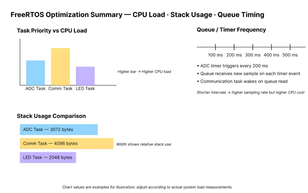
Optimization & Best Practices
Once your multitasking project is stable, you can start improving performance. Optimizing the system helps reduce RAM use, improve timing and lower power consumption.
Here are some simple and effective ways to make the ESP32 run smoother under FreeRTOS.
To make the optimization concepts clearer, the image below summarizes how task priority, CPU usage, stack consumption, and queue timing relate to each other. This gives you a quick visual overview of which parts of the system consume the most resources and how tuning priorities or stack sizes can improve performance and stability.
Tuning Task Priorities & Stack to Save RAM
FreeRTOS lets you fine-tune priorities so tasks run only when needed.
Tips to optimize:
- Keep high priority only for important tasks, such as communication.
- Use medium priority for ADC sampling.
- Low priority works well for LED or user interface tasks.
- Avoid “priority fights” by not giving all tasks the same priority.
- Trim stack sizes once you confirm usage with
uxTaskGetStackHighWaterMark().
A properly tuned priority and stack setup reduces RAM usage and prevents stack overflow resets.
Reducing Latency / Ensuring Responsiveness
To keep the system responsive:
- Avoid long
vTaskDelay()in higher-priority tasks. - Use task notifications instead of semaphores or event groups when you need fast signaling.
- Keep ISR routines short and move logic to tasks.
- Use queues only when needed; large queues increase memory and delay.
Well-designed signaling ensures tasks wake up instantly without wasting CPU time.
Low-Power Considerations (Using Idle, Sleep Modes)
FreeRTOS automatically creates an Idle Task.
If no task is running, the ESP32 enters a light low-power mode.
To save even more power:
- Reduce timer frequency if high-speed sampling is not needed.
- Use
vTaskSuspend()for tasks that remain inactive. - Combine sensor reads to minimize wake-up cycles.
- Use ESP-IDF power features like
- Light Sleep
- Modem Sleep
- Deep Sleep (covered later)
These techniques can greatly extend battery life.
Download ESP32 FreeRTOS Multitasking Project Files
Complete ESP-IDF project with three concurrent FreeRTOS tasks — ADC sensor task with queue output, UART communication task with queue receive, LED indicator task with task notification, and software timer for periodic ADC triggering — support the work if it helped you.
FreeRTOS Multi Task Project: Frequently Asked Questions
Conclusion
This project demonstrates that FreeRTOS is not just a collection of APIs — it's an architecture. Each task has one job, tasks communicate through queues and notifications (never shared globals), timing is handled by a software timer rather than a blocking delay, and the LED task gives you real-time visual feedback on system state without adding complexity to the tasks it monitors.
The template here is directly reusable: swap the ADC for any sensor over I²C or SPI, replace UART with Wi-Fi or MQTT, and add more LED states as your application grows. The FreeRTOS patterns — queue for data, notification for signals, timer for periodic work, priority for scheduling — stay the same regardless of what the tasks actually do.
This completes the ESP32 FreeRTOS series. From basic task creation in Part 1 through the scheduler, priorities, communication, timers, and task control — you now have the full toolkit for building structured, real-time embedded applications on ESP32.
Browse More ESP32 FreeRTOS Tutorials
FreeRTOS ESP32 Scheduler: Task States & Context Switching
ESP32 FreeRTOS Task Priority & Stack Size: Full Guide
ESP32 FreeRTOS Queues, Semaphores, Mutexes & Event Groups
ESP32 FreeRTOS Software Timers & Task Notifications
ESP32 FreeRTOS: Suspend, Resume & Delete Tasks (ESP-IDF)

Subscribe
Login
0 Comments
Newest
