ESP32 ADC One‑Shot Mode Tutorial
Learn ESP32 ADC one-shot mode to read multiple ADC1/ADC2 channels, configure attenuation & calibration in ESP-IDF, and display raw & voltage readings. The project is available to download at the end of this post.
Recommended resources:
This is the 8th tutorial in the ESP32 series using the espressif-IDF and and 1st in the mini series covering ADC peripheral in ESP32. You do not need the knowledge of previous tutorials in order to continue with this one.
VIDEO TUTORIAL
You can check the video to see the complete explanation and working of this project.
Introducing the ADC peripheral in ESP32
The Analog-to-Digital Converter (ADC) in the ESP32 is a built-in hardware module that enables the conversion of analog voltage signals into digital values for further processing in firmware. This allows the ESP32 to read input from analog sensors like temperature, light, potentiometers, and more. The ESP32 features two ADC peripherals, ADC1 and ADC2, which together provide multiple input channels and flexible configuration options.
The ADC hardware in ESP32 supports various modes of operation such as one-shot mode, continuous mode, and DMA mode (on newer chips), making it suitable for both low-latency and high-throughput applications.
ESP32 has 2 ADC units, which can be used in scenarios like:
- Generate one-shot ADC conversion result
- Generate continuous ADC conversion results
Below is the image showing the ADC channels on the ESP32 dev board.
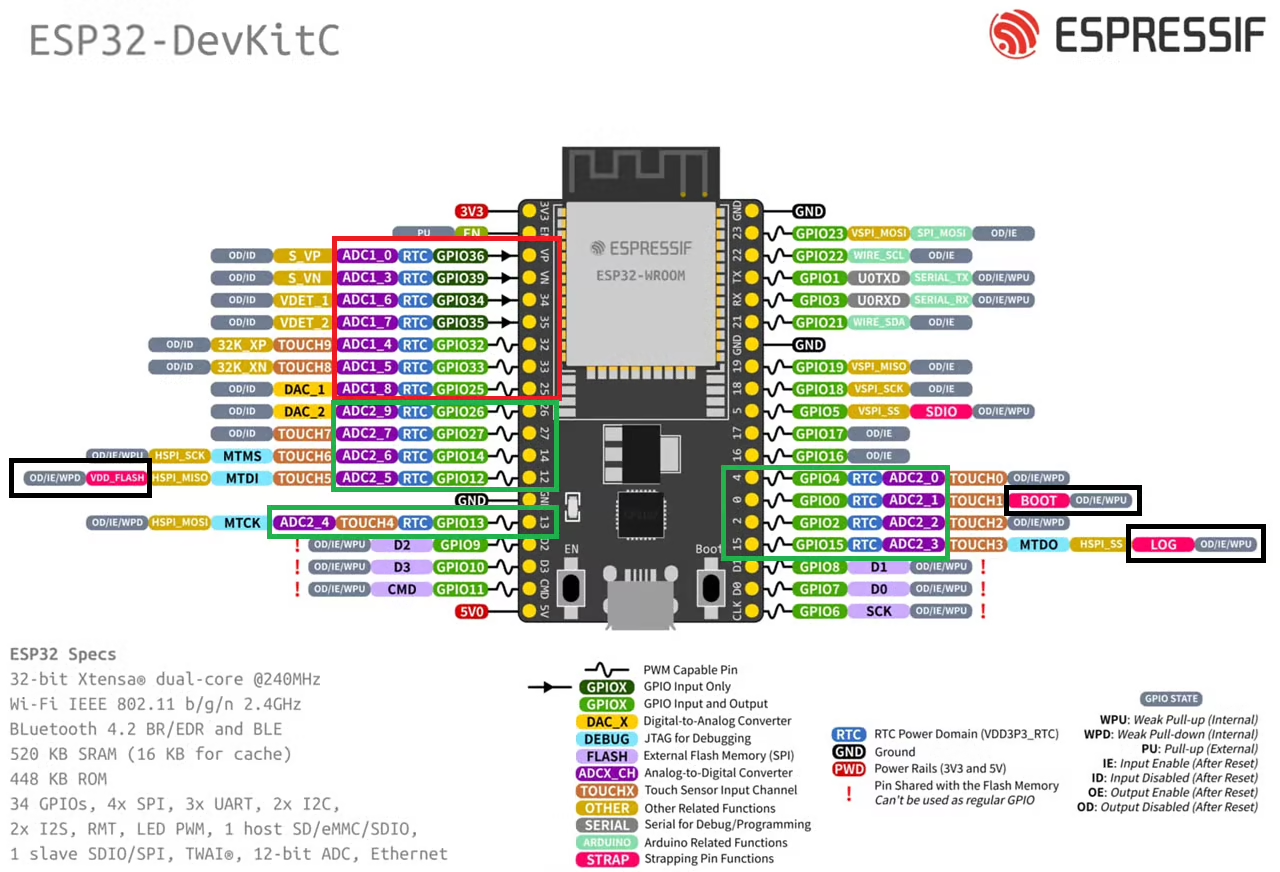
The Red box in the image above highlights the ADC1 channels, whereas the Green box highlights the ADC2 channels. We can use either of these ADC units. Just try to avoid the pins highlighted with Black box. These are the strapping pins which are used during flashing the chip. Therefore in order to use these pins for some other purpose, they require additional configuration.
I am going to read the ADC1 channel 0 (VP) and channel 3 (VN) using the one shot mode. In this mode the ADC reads only one channel at a time. Therefore to read multiple channels, we need to read the each channel separately.
WIRING DIAGRAM
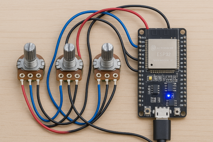
Below is the image showing the potentiometers connected to the ESP32 board.
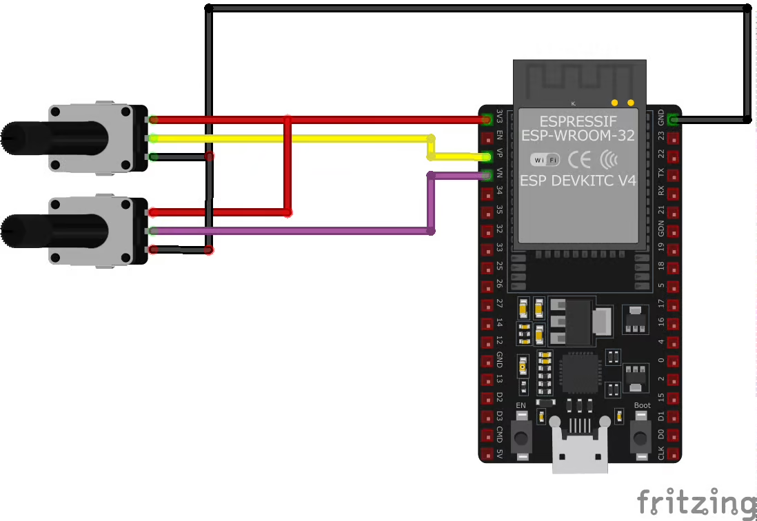
Both the potentiometers are connected between 3.3V and gnd of the ESP32 board. The out pins from the potentiometers are connected to the ADC1 Channel 0 (VP) and Channel 3 (VN).
THE CODE
Global Definitions
Below are some definitions that we will use in the entire code.
adc_channel_t channels[2] = {ADC_CHANNEL_0, ADC_CHANNEL_3};
adc_oneshot_unit_handle_t adc1_handle;
static int adc_raw[2];
static int voltage[2];

adc_cali_handle_t adc1_cali_chan0_handle = NULL;
adc_cali_handle_t adc1_cali_chan1_handle = NULL;- The channels array stores the channels that we will convert using the one shot mode.
- The adc1_handle is the one shot handle which will be used throughout the code.
- adc_raw[2] is an array to store the RAW data for both the channels.
- voltage[2] is an array to store the converted voltage data for both channels.
- adc1_cali_chan0_handle and adc1_cali_chan1_handle are the calibration handles for both channels.
ADC Initialization
We will break down the initialization function into multiple parts. Let’s start with ADC unit initialization.
Unit Initialization
Below is the method to initialize the ADC unit.
adc_oneshot_unit_init_cfg_t unitConfig = {
	.unit_id = ADC_UNIT_1,  // ADC1
};
adc_oneshot_new_unit(&unitConfig, &adc1_handle);The structure unitConfig stores all the important information about the ADC1. The members of this structure are mentioned below:
- unit_id is the ADC unit we will use. I am using the ADC_UNIT_1.
- The other members of this structure are not defined here, that means they are kept to default. It includes the default clock source and the Ultra Low Power Mode is disabled.
The function adc_oneshot_new_unit initializes the ADC unit configured in the above structure. It also takes the pointer to the one shot handle as the parameter.
Channel Initialization
After initializing the ADC, we will initialize the channels. Below is the method to initialize the ADC channels.
adc_oneshot_chan_cfg_t channelConfig = {
.atten = ADC_ATTEN_DB_12, // 150mV - 2450mV
.bitwidth = ADC_BITWIDTH_12, // resolution 12 bit
};
for (int i=0; i<numChannels; i++)
{
adc_oneshot_config_channel(adc1_handle, channel[i], &channelConfig);
}The structure channelConfig stores the information about the ADC channels. The members of this structure are mentioned below:
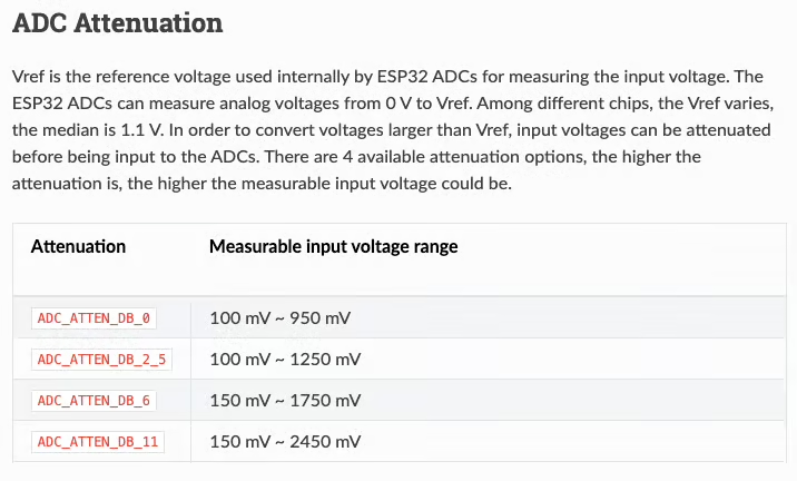
- atten is the voltage attenuation to be used before it is input to the ADC. I am using the attenuation of 12dB, which allows us to measure voltages up to 2450mV. The details for the attenuation is shown in the image below.
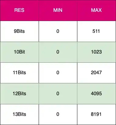
- bitwidth is the resolution for the channel. It ranges from 9Bits to 13 Bits. The higher the resolution the precise is the measurement, but it also takes more time to convert the respective channel. I am using the 12bits resolution.
I am going to configure both the channels with the same above configuration. Therefore the function adc_oneshot_config_channel is called twice in a for loop. The parameters of this function are:
- adc1_handle is the one shot handle, we defined globally.
- channel[i] is the ADC channel from the channels array we define globally.
- channelConfig is the channel configuration we define above.
Calibration
We will now calibrate both the channels we configured above. Below is the function to calibrate the channel.
adc_calibration_init(ADC_UNIT_1, channels[0], ADC_ATTEN_DB_12, &adc1_cali_chan0_handle);
adc_calibration_init(ADC_UNIT_1, channels[1], ADC_ATTEN_DB_12, &adc1_cali_chan1_handle);The adc_calibration_init function is used to calibrate a single ADC channel. We will discuss the details of this function in a while. The parameters of this function are:
- ADC_UNIT_1 is the ADC unit we are using.
- channels[0] is the ADC channel (ADC_CHANNEL_0) we want to calibrate.
- ADC_ATTEN_DB_12 is the attenuation we are using.
- adc1_cali_chan0_handle is the calibration handle for this channel.
Since we are using 2 ADC channels in this tutorial, we need to calibrate them separately.
Final ADC Initialization Function
Below is the ADC initialization function, which is a combination of everything we discussed above.
void adc_init (adc_channel_t *channel, uint8_t numChannels)
{
adc_oneshot_unit_init_cfg_t unitConfig = {
	.unit_id = ADC_UNIT_1,  // ADC1
};
adc_oneshot_new_unit(&unitConfig, &adc1_handle);
adc_oneshot_chan_cfg_t channelConfig = {
	.atten = ADC_ATTEN_DB_12,  // 150mV - 2450mV
	.bitwidth = ADC_BITWIDTH_12,  // resolution 12 bit
};

for (int i=0; i<numChannels; i++)
{
	adc_oneshot_config_channel(adc1_handle, channel[i], &channelConfig);
}
//-------------ADC1 Calibration Init---------------//
adc_calibration_init(ADC_UNIT_1, channels[0], ADC_ATTEN_DB_12, &adc1_cali_chan0_handle);
adc_calibration_init(ADC_UNIT_1, channels[1], ADC_ATTEN_DB_12, &adc1_cali_chan1_handle);
}ADC Calibration
In ESP32, the analog-to-digital converter (ADC) compares the input analog voltage to the reference, and determines each bit of the output digital result. By design, the ADC reference voltage for ESP32 is 1100 mV. However, the true reference voltage can range from 1000 mV to 1200 mV among different chips. The ADC calibration is used to minimize the effect of different reference voltages, and get more accurate output results.
ESP32 ADC supports two types of calibration schemes:
- ADC Calibration Line fitting scheme
- ADC Calibration Curve fitting scheme
You can read more details about these schemes in the ESP32 Docs. We will focus on the initialization function.
static bool adc_calibration_init(adc_unit_t unit, adc_channel_t channel, adc_atten_t atten, adc_cali_handle_t *out_handle)
{
    adc_cali_handle_t handle = NULL;
    esp_err_t ret = ESP_FAIL;
    bool calibrated = false;

#if ADC_CALI_SCHEME_CURVE_FITTING_SUPPORTED
    if (!calibrated) {
        ESP_LOGI(TAG, "calibration scheme version is %s", "Curve Fitting");
        adc_cali_curve_fitting_config_t cali_config = {
            .unit_id = unit,
            .chan = channel,
            .atten = atten,
            .bitwidth = ADC_BITWIDTH_DEFAULT,
        };
        ret = adc_cali_create_scheme_curve_fitting(&cali_config, &handle);
        if (ret == ESP_OK) {
            calibrated = true;
        }
    }
#endif

#if ADC_CALI_SCHEME_LINE_FITTING_SUPPORTED
    if (!calibrated) {
        ESP_LOGI(TAG, "calibration scheme version is %s", "Line Fitting");
        adc_cali_line_fitting_config_t cali_config = {
            .unit_id = unit,
            .atten = atten,
            .bitwidth = ADC_BITWIDTH_DEFAULT,
        };
        ret = adc_cali_create_scheme_line_fitting(&cali_config, &handle);
        if (ret == ESP_OK) {
            calibrated = true;
        }
    }
#endif

    *out_handle = handle;
    if (ret == ESP_OK) {
        ESP_LOGI(TAG, "Calibration Success");
    } else if (ret == ESP_ERR_NOT_SUPPORTED || !calibrated) {
        ESP_LOGW(TAG, "eFuse not burnt, skip software calibration");
    } else {
        ESP_LOGE(TAG, "Invalid arg or no memory");
    }

    return calibrated;
}The function adc_calibration_init takes the following parameters:
- unit is the ADC unit we are using.
- channel is the ADC channel we want to calibrate.
- atten is the attenuation level we are using.
- out_handle is the pointer to the calibration handle for this channel.
The function can calibrate the respective channel for both the calibrating scheme. The structure cali_config stores the information passed in the parameters of this function.
Then the calibration function adc_cali_create_scheme_curve_fitting or adc_cali_create_scheme_line_fitting is called based on which scheme is supported by the respective ESP32 board.
The main function
Inside the main function we will initialize the ADC first and then read the channels inside the while loop.
void app_main(void)
{
    adc_init(channels, 2);

    while (1) {
		adc_oneshot_read(adc1_handle, channels[0], &adc_raw[0]);  // read channel 0
		adc_cali_raw_to_voltage(adc1_cali_chan0_handle, adc_raw[0], &voltage[0]);

		adc_oneshot_read(adc1_handle, channels[1], &adc_raw[1]);  // read channel 0
		adc_cali_raw_to_voltage(adc1_cali_chan1_handle, adc_raw[1], &voltage[1]);

		for (int i=0; i<2; i++){
		printf ("CHANNEL%d\t RAW=%d\t mV=%d\n", channels[i], adc_raw[i], voltage[i]);
		}

		usleep(500000);  // 500ms sleep
    }
}The function adc_init is used to initialize the ADC and its channels. The parameters of this function are as follows:
- channels is the channel array we defined globally. It contains the ADC channels we want to read.
- 2 is the number of channels we want to read.
Inside the while loop we will read the channels individually and then convert the raw data to voltage value.
The function adc_oneshot_read is used to read the raw data from a particular ADC channel. The parameters of this function are:
- adc1_handle is the ADC one shot handle we defined globally.
- channels[0] is the ADC channel (ADC_CHANNEL_0) we want to convert.
- adc_raw[0] is the variable where we want to store the received data.
Once the raw data from the channel is read, we will convert it to the voltage using the calibrated data for the channel. The function adc_cali_raw_to_voltage is used for the same. The parameters of this function are:
- adc1_cali_chan0_handle is the calibration handle for this particular channel.
- adc_raw[0] is the variable where the raw data for the channel is stored.
- voltage[0] is the variable where we want to store the converted voltage data.
Since we are using 2 channels, we need to read and convert both of them separately.
Finally we will print the channel number, raw data and converted voltage data on the terminal.
RESULT
Below is the image showing the output on the terminal and the reading on the voltmeter.
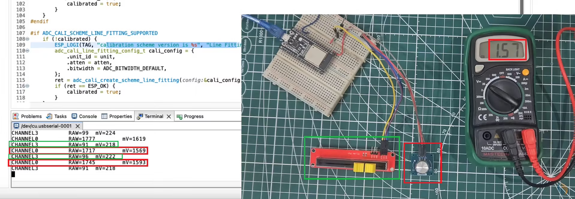
The Green boxes indicates the measurement for ADC_CHANNEL_3. The sliding potentiometer is connected to this channel. You can see the Raw and voltage data for this channel is printed on the console.
The Red boxes indicates the measurement for the ADC_CHANNEL_0. The rotary potentiometer is connected to this channel. The voltmeter is also connected to the potentiometer output. You can see the printed voltage value is approximately same as the one measured by the voltmeter.
This means that the ADC peripheral of the ESP32 can measure the input analog voltage to some degree of accuracy. We are getting the data from both the channels as well.
PROJECT DOWNLOAD

