Updated On: February 22, 2026
How to use Interrupt & DMA to Transmit Data
In many projects, UART data is transmitted using blocking functions, which can pause the CPU until the entire message is sent. While this approach works for small data, it quickly becomes inefficient in real applications where the microcontroller must handle multiple tasks simultaneously.
In this tutorial, we will explore how to transmit data over UART using Interrupt and DMA modes in STM32. These methods allow UART transmission to run in the background, freeing the CPU to execute other code without delays. We’ll start by understanding the limitations of blocking mode, then move step-by-step through interrupt-based transmission, and finally implement DMA-based transmission for maximum efficiency.
This is the second tutorial in our series on the UART peripheral in STM32 microcontrollers. In the previous tutorial, we discussed how to configure UART and send data using the blocking mode. Here, we’ll explain why blocking mode is not ideal for sending large amounts of data, and how using interrupt or DMA methods can make the process more efficient.
You should also take a look at the following:
Why Use Interrupt and DMA for UART Transmission?
When sending data over UART, the traditional blocking method halts the CPU until the entire message is transmitted. This can cause delays in other tasks like blinking LEDs, reading sensors, or handling real-time events. To overcome this, STM32 provides interrupt-based and DMA-based UART transmission, which allow the CPU to work on other tasks while data is being sent.
How Interrupt-Based UART Works
- The UART peripheral generates an interrupt after each byte or when the transmission is complete.
- The CPU handles the data transfer in the background, only reacting when necessary.
- Ideal for moderate data transfers without fully blocking the system.
How DMA-Based UART Works
- DMA (Direct Memory Access) moves data directly from memory to the UART peripheral without CPU involvement.
- The CPU is completely free to run other code while large or continuous data is sent.
- Perfect for logging, streaming data, or high-speed transfers.
Benefits of Using Interrupt or DMA
- Reduces CPU idle time during transmission.
- Improves real-time performance of other tasks.
- Enables reliable transmission of large or continuous data streams.
- Provides flexibility to choose between moderate and minimal CPU involvement depending on the project requirements.
The table below shows the comparison between the UART transmission in Blocking Mode vs Interrupt and DMA.
| Feature | Blocking Mode | Interrupt Mode | DMA Mode |
|---|---|---|---|
| CPU Usage | High – CPU waits for each byte | Medium – CPU only handles interrupts | Low – CPU free while DMA transfers data |
| Complexity | Simple to implement | Moderate – requires interrupt handling | Moderate – requires DMA setup |
| Best For | Small, infrequent data | Medium-size transfers, background tasks | Large data, continuous streaming |
| Real-Time Performance | Poor – blocks other tasks | Good – CPU can do other work | Excellent – CPU fully free |
| Example HAL Function | HAL_UART_Transmit() | HAL_UART_Transmit_IT() | HAL_UART_Transmit_DMA() |
STM32 UART Hardware Setup
We will use the STM32 MCU to send the data to the computer. Some of the Nucleo and Discovery dev boards from ST supports the virtual com port. This feature enables the USB connected for the ST-link to be also used for the data transmission between the MCU and the computer.
The Virtual Com Port is supported by many Nucleo and Discovery boards but not all. You need to check the schematic of the board to confirm whether the respective board supports it.
Below are the images from the schematic of the Nucleo F446RE and Discovery F412.
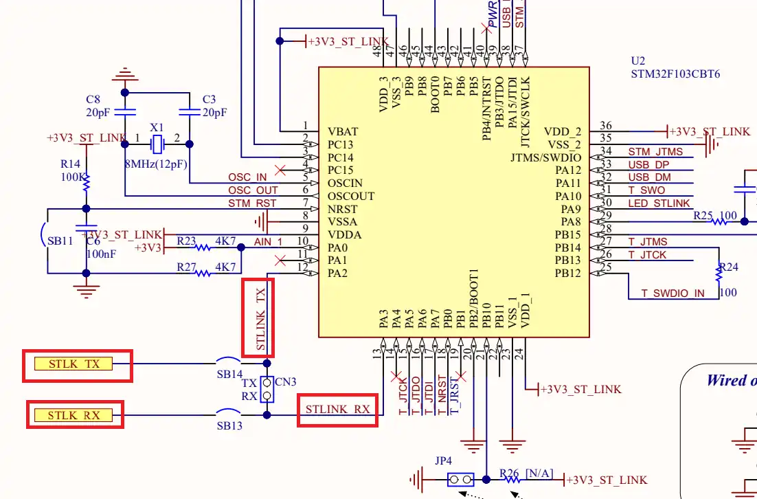
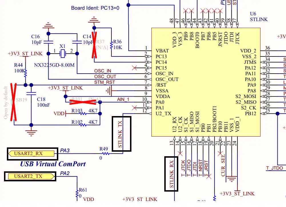
As you can see in the images above, both Nucleo F446RE and Discovery F412 supports the USB Virtual Com Port. So if you are using either of these boards, you do not need to use an additional module to communicate to the computer. The USB used for the ST link can also be used for the communication.
Not all the boards support this Virtual Com port feature. Below is the image from the schematic of the very famous STM32F4 Discovery board.
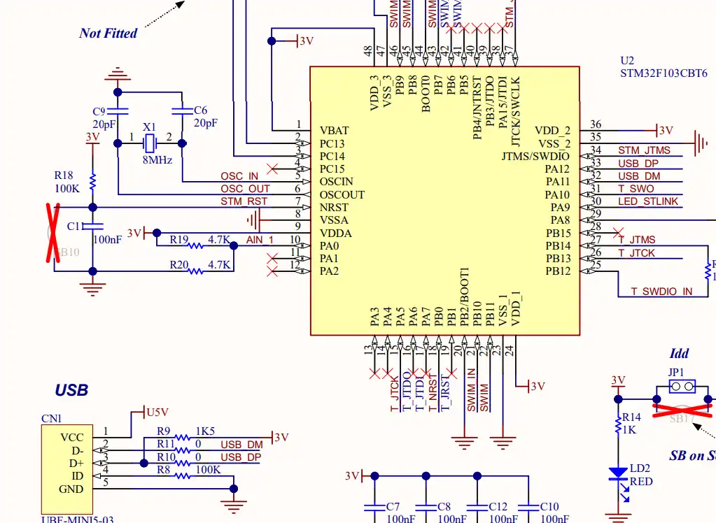
As you can see in the image above, there is no virtual com port in the F4 Discovery board. In such cases we can use some module to convert the UART signals to the USB, which is connected to the computer.
The image below shows the connection between the MCU and the FT232 USB to UART converter.
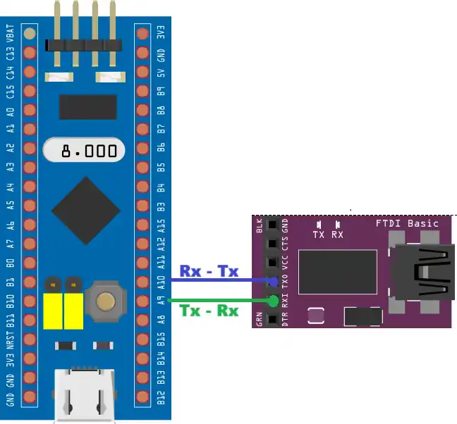
The UART is always connected in the cross connection, connecting the TX pin of the MCU to the RX of the device and the RX to the TX of the device. The module then connects to the computer using the USB.
Try Sending Large data in blocking mode
Let’s assume a case where we want to send 10 kilobytes of data continuously via the UART. We will also blink a LED periodically indicating a process that needs to run at a fixed interval. Below is the code to send the data in the blocking mode.
uint8_t TxData[10240];
int main()
{
  ...
  /* Fill array with some data */
  for (uint32_t i=0; i<10240; i++)
{
	  TxData[i] = i&(0xff);
  }
  while (1)
  {
    HAL_UART_Transmit(&huart2, TxData, 10240, HAL_MAX_DELAY);
    HAL_GPIO_TogglePin(GPIOA, GPIO_PIN_5);
    HAL_Delay(500);
  }
}Here we defined a 10 KB array. Then filled the array with some data in the main function. The data is sent to the UART in the while loop and the timeout is set to HAL_MAX_DELAY. This basically means the function will never timeout and it can take as much time as it wants to send the data. After the data is sent, the LED will toggle and the loop repeats every 500ms.
As I mentioned the LED blinking can be assumed as a process which runs periodically. The data transmission should not affect the rate of this process.
But this does not takes pace as expected. Below is the gif showing the LED blinking rate.
You can see the LED is taking more than 500 ms to blink. This is because the UART transfer is taking significant amount of time and it blocks the CPU while transmitting the data. This affects other processes as they have to wait for the CPU.
This issue generally arise when transferring large amount of data. Small data is transferred in an instant, so we don’t need to worry about that.
To solve this issue, the data needs to be transmitted in the background while the CPU can process other tasks. This is why we use interrupt or DMA in the first place.
Using UART Interrupt to transmit Data
Interrupt can be used to send the data to the UART in the background. While the transmission is taking place, the CPU can process other tasks as well. Note that even the data transmission takes place in the background, the data is still transmitted by the CPU, so it still puts the load on the CPU.
STM32 Cubemx Configuration
Below is the cubeMX configuration for the interrupt.
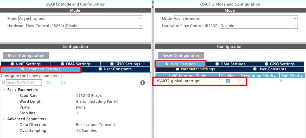
I am keeping the same configuration as used in the previous tutorial. Here we will just enable the UART interrupt in the NVIC tab.
HAL Code to Transmit UART data in Interrupt Mode
The data sent using interrupt is transferred in the background. Once the data is sent completely, an interrupt will trigger and the transfer complete callback is called.
int isSent = 1;
void HAL_UART_TxCpltCallback(UART_HandleTypeDef *huart)
{
	isSent = 1;
	countinterrupt++;
}Inside the callback we will increment the interrupt counter. This keeps track of how many times the callback was called. We also set the variable isSent indicating that the data has been transferred. This is to make sure that CPU sends the data again only after the previous data has been transferred.
To do so, we will guard the Transmit function with the condition as shown below.
int main()
{
...
...
while (1)
{
if (isSent == 1)
{
HAL_UART_Transmit_IT(&huart2, TxData, 10240);
isSent = 0;
}
HAL_GPIO_TogglePin(GPIOA, GPIO_PIN_5);
HAL_Delay(500);
countloop++;
}
}The HAL_UART_Transmit_IT is used to transfer the data in the interrupt mode. The function only runs if the previous data has been transmitted. We toggle the LED at the normal rate of 500ms and also increment the loop counter. This keeps track of how many times the while loop runs.
Result of Interrupt based transmission
Below is the image showing the loop counters after running the code for few seconds.
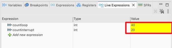
As you can see the interrupt counter is half of that of the loop counter. Actually the loop is running every 500ms and the interrupt is only triggered once the data is sent completely, which is taking around 1 second.
Below is the gif showing the LED blinking.
The LED blinks every 500ms. This means the CPU is not blocked for the transmission and it can process the rest of the tasks while the data is being transmitted in the background.
Using UART DMA to Transmit Data
The Direct memory access (DMA) is used to provide high-speed data transfers between peripherals and memory and between memory and memory. Data can be quickly moved by the DMA without any CPU action. This keeps CPU resources free for other operations.
STM32 CubeMx Configuration
Below is the cubeMX configuration for the DMA mode.
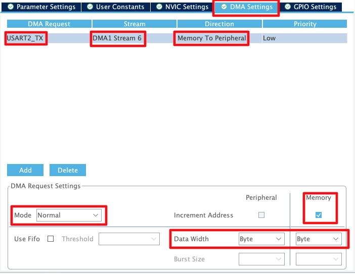
- The DMA Request is set to USART_TX as we want to use DMA to send the data.
- The DMA Stream is selected automatically by the cubeMX. It is basically the DMA channel that we are going to use for the data transmission.
- The direction is Memory to Peripheral as we are sending the data from the MCU memory to the UART peripheral.
- The Data width is set to Byte as we are sending one byte data to the UART.
- After sending 1 byte, the memory address will increment so it can send the next data byte.
The DMA can work in 2 modes, Normal and Circular.
- In Normal mode, the DMA sends the data once and then stops automatically. This is just like how we used the interrupt.
- In circular mode, The data flow is continuous. The source address, the destination address and the number of data to be transferred are automatically reloaded after the transfer completes. This allows DMA to continuously transmit the same data until we issue the stop command manually.
Sending data in normal DMA mode
In Normal mode, the DMA stops after sending the data completely. An interrupt will trigger and the transfer complete callback is called. We will send data the same way we did in case of the interrupt.
int isSent = 1;
void HAL_UART_TxCpltCallback(UART_HandleTypeDef *huart)
{
	isSent = 1;
	countinterrupt++;
}
int main()
{
...
...
while (1)
{
if (isSent == 1)
{
HAL_UART_Transmit_DMA(&huart2, TxData, 10240);
isSent = 0;
}
HAL_GPIO_TogglePin(GPIOA, GPIO_PIN_5);
HAL_Delay(500);
countloop++;
}
}The HAL_UART_Transmit_DMA is used to transfer the data in the DMA mode. The function only runs if the previous data has been transmitted. We toggle the LED at the normal rate of 500ms and also increment the loop counter. This keeps track of how many times the while loop runs.
Below is the image showing the loop counters after running the code for few seconds.
As you can see the interrupt counter is half of that of the loop counter. Actually the loop is running every 500ms and the interrupt is only triggered once the data is sent completely, which is taking around 1 second.
Below is the gif showing the LED blinking.
The LED blinks every 500ms. This means the CPU is not blocked for the transmission and it can process the rest of the tasks while the data is being transmitted in the background. Since DMA is being used to transfer the data, the CPU load is also reduced.
Sending data in circular DMA mode
We first need to select the Circular mode in the cubeMX configuration as shown below.
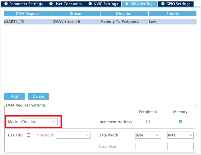
In circular mode the Data is transmitted continuously. Once all the data has been sent, the DMA reloads the same data again and sends it. We can also update the data in the runtime and use the DMA more efficiently.
Actually the 2 interrupts gets triggered while transmitting the data via the DMA. The Half Transmit Complete callback is called when the DMA finished transferring half the data and the Transmit complete callback is called when the DMA transferred all the data. For example, if we are transferring 10KB data, the HT Callback will be called when DMA finished transferring 5KB and the TC Callback will be called when DMA finished transferring 10KB.
When the HT callback is called, the DMA is still transferring the 2nd half of the buffer. In that time, we can load a new data to the first half of the TX buffer.
int indx = 49;  // char '1'

void HAL_UART_TxHalfCpltCallback(UART_HandleTypeDef *huart)
{
	  for (uint32_t i=0; i<5120; i++)
	  {
		  TxData[i] = indx;
	  }
	  indx++;
}Similarly, when the TC callback is called, the DMA is start transferring the 1st half of the buffer. In that time, we can load a new data to the 2nd half of the TX buffer.
void HAL_UART_TxCpltCallback(UART_HandleTypeDef *huart)
{
	  for (uint32_t i=5120; i<10240; i++)
	  {
		  TxData[i] = indx;
	  }
	  indx++;

	  if (indx>=60)
	  {
		  HAL_UART_DMAStop(&huart2);
	  }
	isSent = 1;
	countinterrupt++;
}This way we are loading a new data to the DMA in parallel to the previous data transfer.
This loop keeps running till we issue the stop command. Here we will set a condition and stop the DMA when the condition is satisfied.
We still need to call the DMA once in the main function, so that everything can start from there.
int main ()
{
  /* Fill array with some data */
  for (uint32_t i=0; i<10240; i++)
  {
	  TxData[i] = i&(0xff);
  }

  HAL_UART_Transmit_DMA(&huart2, TxData, 10240);


  while (1)
  {
    HAL_GPIO_TogglePin(GPIOA, GPIO_PIN_5);
    HAL_Delay(500);
    countloop++;
  }
}Video Tutorial
STM32 UART Transmit Data Using Interrupt & DMA
Learn how to configure UART2 on STM32 and transmit data efficiently using **Interrupt and DMA modes**. This step-by-step video walkthrough demonstrates CubeMX setup, HAL coding, and testing, showing how to free the CPU while sending data and improve real-time performance.
Watch the VideoConclusion
In this tutorial, we explored how to transmit data over UART on STM32 using both Interrupt and DMA modes, and why these methods are far more efficient than the traditional blocking approach. By using interrupts, the CPU only reacts when necessary, allowing other tasks to run alongside UART communication. With DMA, the CPU is completely free, while the peripheral hardware handles the data transfer in the background. These techniques are essential for real-time applications, large data transfers, and projects where multiple tasks need to run simultaneously.
Understanding the differences between blocking, interrupt, and DMA modes enables you to choose the right method for your project. For small or simple messages, blocking mode might suffice, but for performance-critical or continuous data applications, interrupt and DMA-based UART transmissions are the clear winners. Implementing these methods in your STM32 projects not only improves efficiency but also enhances the overall responsiveness and reliability of your system.
Browse More STM32 UART Tutorials
STM32 UART Part 3 – Receive Data in Blocking & Interrupt mode
STM32 UART DMA Receive: Normal & Circular Mode (HAL)
STM32 UART Idle Line: Receive Data via Interrupt & DMA
STM32 UART Part 6 – Half-Duplex Communication (Single-Wire Mode)
STM32 UART Part 7 – How to use one-Wire Protocol
STM32 UART Part 8 – LIN Communication Tutorial
STM32 UART Part 9 – LIN Transceiver Connections & Master-Slave Communication
STM32 UART Project Download
STM32 UART FAQs

Subscribe
Login
0 Comments
Newest
