Published: December 8, 2024
Last Updated: March 23, 2026
Last Updated: March 23, 2026
How to Read Multiple ADC Channels without DMA in STM32
Master STM32 ADC reading on multiple channels without DMA. This tutorial includes CubeMX setup and HAL C code for STM32F1, F4, and H7 to read channels individually. The project is available to download at the end of the post.
Recommended Resources:
This is the 5th tutorial in the STM32 ADC series. In the previous tutorials we covered how to configure the ADC in STM32 F1, F4 and F7 series and how to use it in the single channel polling, interrupt and DMA modes to read the potentiometer data. We have also covered the Multiple channels in DMA Normal Mode and Circular Mode.
You should take a look at the following tutorials before continuing here:
- STM32 ADC Single Channel Polling Mode
- STM32 ADC Single‑Channel Interrupt & DMA Modes
- STM32 ADC Multi-Channel DMA (Normal Mode)
- STM32 ADC Multi‑Channel Circular DMA Mode
What is Multi-Channel ADC Without DMA?
In STM32, the ADC (Analog-to-Digital Converter) can be configured to sample multiple analog channels such as sensors, potentiometers, or external signals. In a multi-channel ADC without DMA, the ADC converts each channel sequentially, and the CPU manually reads the conversion results.
When scan mode is enabled, the ADC cycles through the configured channels based on their rank order. After each conversion (or after the full sequence), the CPU reads the ADC data register using polling or interrupt-based methods. Unlike DMA-based approaches, all data handling is performed directly by the CPU.
This method is simple and gives full software control over when and how each ADC value is read, making it suitable for basic and low-speed applications.
Why Read multiple channels without DMA?
Reading multiple ADC channels without DMA is useful when the number of channels is small and sampling speed is not critical. Since the CPU directly manages ADC conversions and data reads, the behavior is predictable and easy to debug.
Compared to DMA-based methods, this approach avoids buffer management and DMA configuration, which can be beneficial for learning, testing, or quick prototyping.
Advantages of reading Without DMA
- Simple to configure and understand.
- No DMA setup or memory buffers required.
- Full control over channel conversion sequence.
- Easy to debug and validate ADC readings.
- Well suited for low sampling rate applications.
Best Use Cases for Multi-Channel ADC Without DMA
- Reading a few sensors at low sampling rates.
- Educational projects and learning ADC fundamentals.
- Debugging ADC behavior and signal validation.
- Simple embedded applications with minimal real-time constraints.
STM32 CubeMX Configuration
We will connect 4 potentiometers to the 4 channels of the same ADC. As I mentioned, we will then fetch the data from any channel we want.
We will see the available configuration for all three MCUs, F103C8, F446RE and H750VB.
STM32F103C8 ADC Configuration
Let’s start with the STM32F103C8. Below is the image showing the configuration for the it.
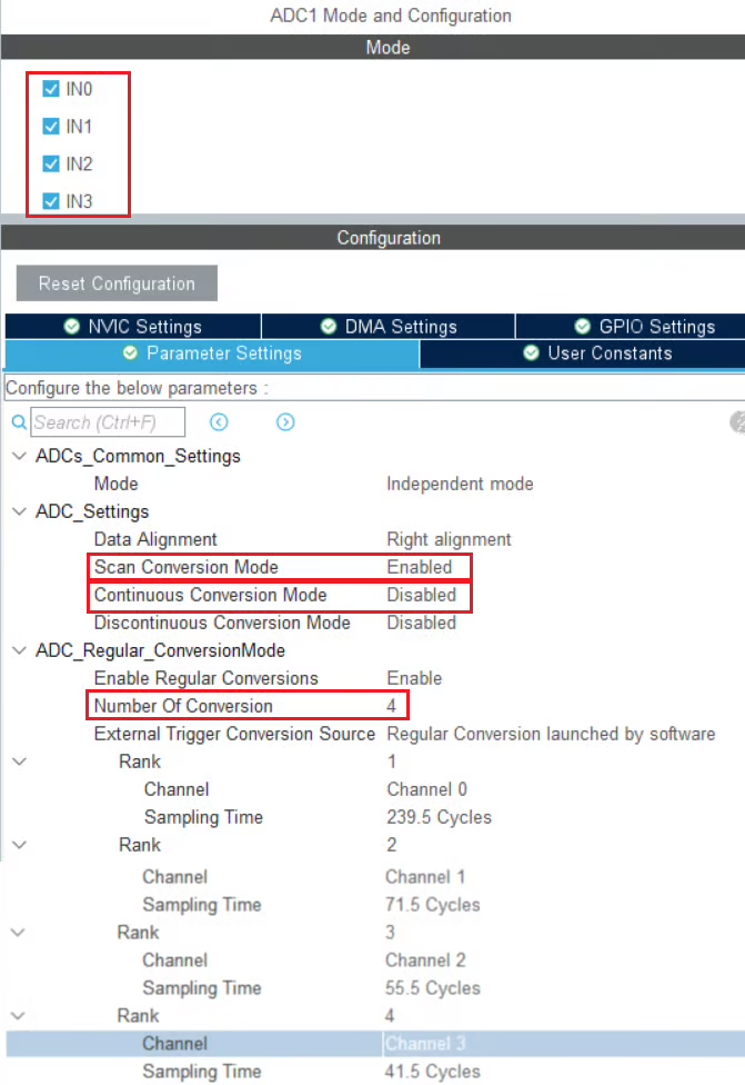
I have enabled 4 channels of the ADC1. This is where the 4 potentiometers will be connected to.
Since we are using 4 different Channels of ADC1, set the Number of Conversions (under ADC_Regular_ConversionMode) to 4. This will automatically enable the Scan Conversion Mode, which is necessary in case of Multiple Channels.
You can configure the Rank and Sampling Time for each channel. The Rank determines the sequence in which the channels will be converted.
The Continuous Conversion Mode should be Disabled. We want to convert only 1 channel at a time, and also we want the channel to only convert when we initiate it with the command. Therefore this mode should be disabled.
Here despite using the multiple channels, we are not using the DMA.
STM32F446RE ADC Configuration
Below is the image showing the configuration for the F446RE.
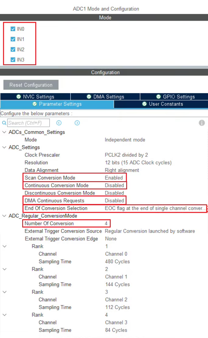
I have enabled 4 channels of the ADC1. This is where the 4 potentiometers will be connected to.
Since we are using 4 different Channels of ADC1, set the Number of Conversions (under ADC_Regular_ConversionMode) to 4. This will automatically enable the Scan Conversion Mode, which is necessary in case of Multiple Channels.
You can configure the Rank and Sampling Time for each channel. The Rank determines the sequence in which the channels will be converted.
The Continuous Conversion Mode should be Disabled. We want to convert only 1 channel at a time, and also we want the channel to only convert when we initiate it with the command. Therefore this mode should be disabled.
The DMA Continuous Request must also be Disabled. Since we are not using DMA, this mode is of no use.
The End of Conversion Selection should be set at the end of single channel. Doing this will make sure that the Conversion complete flag is set after each channel is converted. Since we are converting 1 channel at a time, this is an important parameter.
Here despite using the multiple channels, we are not using the DMA.
STM32H750VB ADC Configuration
Below is the image showing the configuration for the H750.
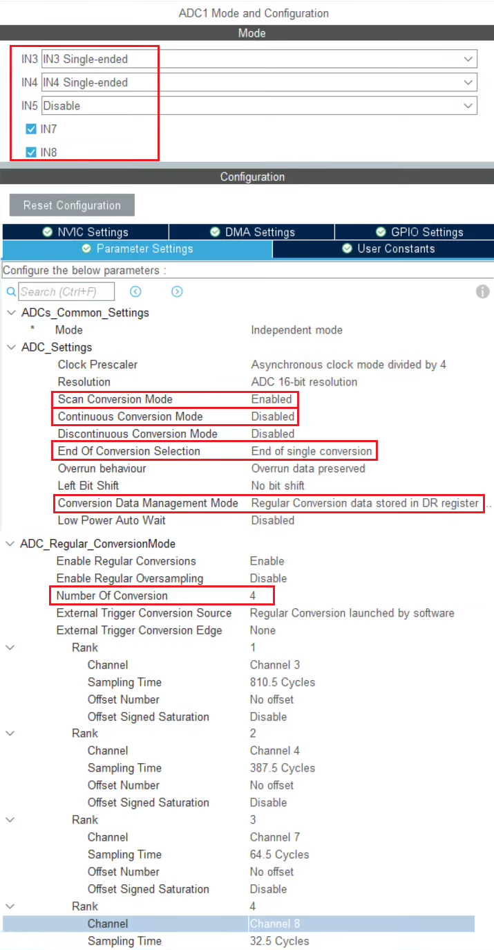
I have enabled 4 channels of the ADC1. This is where the 4 potentiometers will be connected to.
Since we are using 4 different Channels of ADC1, set the Number of Conversions (under ADC_Regular_ConversionMode) to 4. This will automatically enable the Scan Conversion Mode, which is necessary in case of Multiple Channels.
You can configure the Rank and Sampling Time for each channel. The Rank determines the sequence in which the channels will be converted.
The Continuous Conversion Mode should be Disabled. We want to convert only 1 channel at a time, and also we want the channel to only convert when we initiate it with the command. Therefore this mode should be disabled.
The Conversion Data Management Mode should be set to Data Register (DR).
The End of Conversion Selection should be set at the end of single channel. Doing this will make sure that the Conversion complete flag is set after each channel is converted. Since we are converting 1 channel at a time, this is an important parameter.
Here despite using the multiple channels, we are not using the DMA.
Wiring the Potentiometers to ADC Input
The image below shows the connection between 4 potentiometers and the H750.
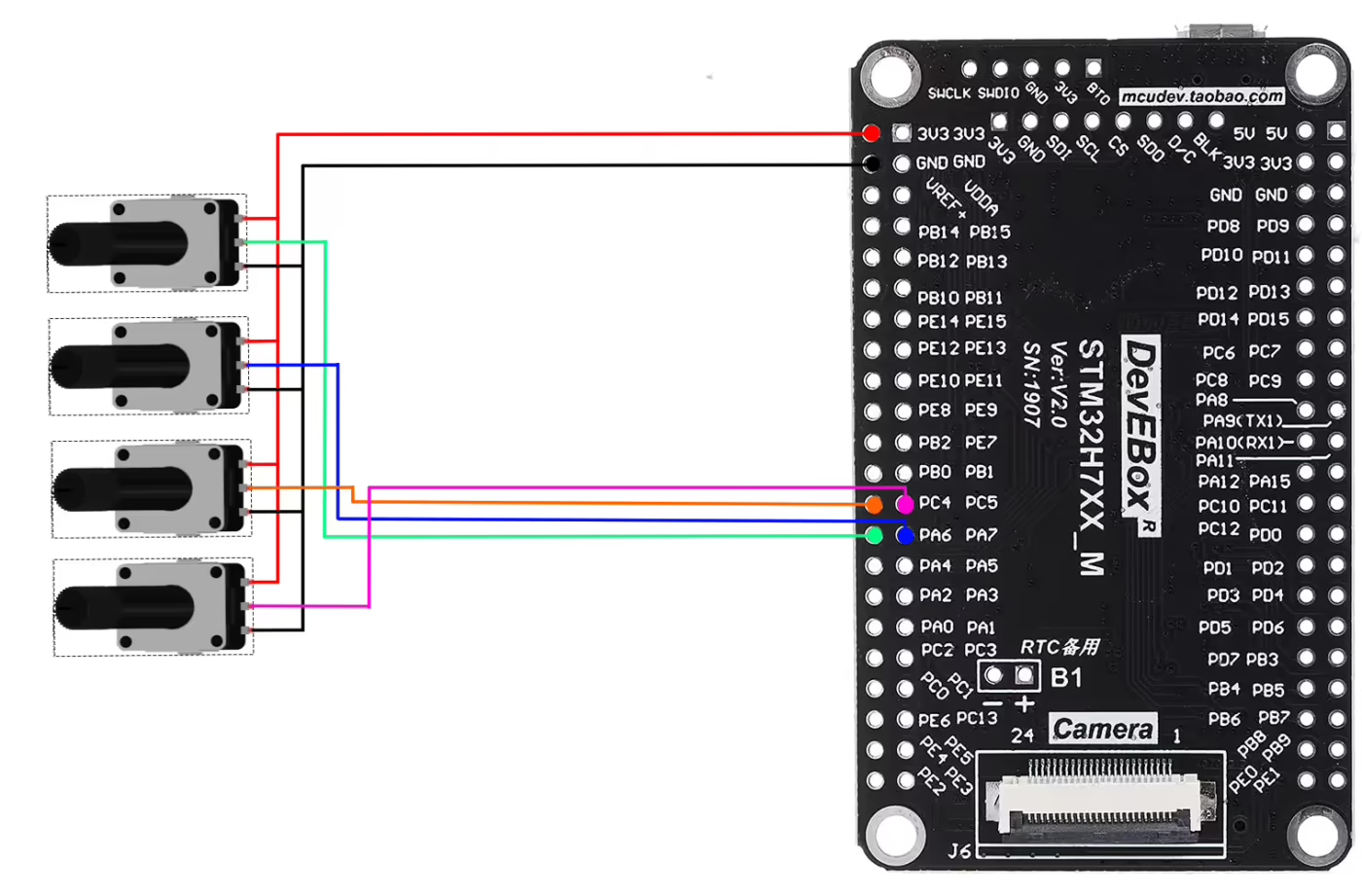
As shown in the image above, four potentiometers are connected to four pins of the MCU. All potentiometers share the same 3.3V supply and GND from the MCU. Only the wiper (signal pin) of each potentiometer is connected to a unique ADC-capable pin on the STM32.
The pin connection is described in the table below.
| Potentiometer | Pin 1 (VCC) | Pin 2 (Signal / Wiper) | Pin 3 (GND) | MCU Pin (ADC Channel) |
|---|---|---|---|---|
| Potentiometer 1 | 3.3V | Middle Pin → Pink Wire | GND | PC5 (ADC Channel 15) |
| Potentiometer 2 | 3.3V | Middle Pin → Orange Wire | GND | PC4 (ADC Channel 14) |
| Potentiometer 3 | 3.3V | Middle Pin → Blue Wire | GND | PA6 (ADC Channel 6) |
| Potentiometer 4 | 3.3V | Middle Pin → Green Wire | GND | PA6 (ADC Channel 6) |
STM32 HAL Code for Reading Multiple ADC Channels
The code will remain the same for all the STM32 MCUs. If there are any changes, I will specify in this section itself.
Definitions
Let’s define some variables, which we will use in the main function later.
uint16_t ADC_VAL[4];ADC_VAL is an array of 4 elements of 16 bit in size. We will use this array to store the converted ADC Value. Even if you are using 10bits, 12bits or 14bits resolution the ADC_VAL will still be defined as a 16 bit variable.
Channel Functions
We will now define functions to convert the ADC channels. Since we are converting 4 channels, we will define 4 functions, 1 function for each channel.
uint16_t ADC_Convert_Rank1 (void)
{
  /* Configure channel */
  ADC_ChannelConfTypeDef sConfig = {0};
  sConfig.Channel = ADC_CHANNEL_3;
  sConfig.Rank = ADC_REGULAR_RANK_1;
  sConfig.SamplingTime = ADC_SAMPLETIME_810CYCLES_5;
  sConfig.SingleDiff = ADC_SINGLE_ENDED;
  sConfig.OffsetNumber = ADC_OFFSET_NONE;
  sConfig.Offset = 0;
  sConfig.OffsetSignedSaturation = DISABLE;
  if (HAL_ADC_ConfigChannel(&hadc1, &sConfig) != HAL_OK)
  {
    Error_Handler();
  }

  /* Convert the Channel */
  HAL_ADC_Start(&hadc1);
  HAL_ADC_PollForConversion(&hadc1, 100);
  uint16_t adcval = HAL_ADC_GetValue(&hadc1);
  HAL_ADC_Stop(&hadc1);
  return adcval;
}The function ADC_Convert_Rank1 is used to convert the Rank 1 i.e Channel 3. The channel configuration is copied from the ADC initialisation function, which is generated by the cubeMX.
Note that the channel 3 is configured with Rank 1 and the sampling time is as we configured in the cubeMX.
We will use the blocking mode to convert the channel. Since we have configured the conversion complete flag to set after each channel, once this particular channel is converted the flag will set and we will get the result.
Below is the function to convert the Rank 2.
uint16_t ADC_Convert_Rank2 (void)
{
	ADC_ChannelConfTypeDef sConfig = {0};
	sConfig.Channel = ADC_CHANNEL_4;
	sConfig.Rank = ADC_REGULAR_RANK_1;
	sConfig.SamplingTime = ADC_SAMPLETIME_387CYCLES_5;
	sConfig.SingleDiff = ADC_SINGLE_ENDED;
	sConfig.OffsetNumber = ADC_OFFSET_NONE;
	sConfig.Offset = 0;
	sConfig.OffsetSignedSaturation = DISABLE;
	if (HAL_ADC_ConfigChannel(&hadc1, &sConfig) != HAL_OK)
	{
		Error_Handler();
	}

	HAL_ADC_Start(&hadc1);
	HAL_ADC_PollForConversion(&hadc1, 100);
	uint16_t adcval = HAL_ADC_GetValue(&hadc1);
	HAL_ADC_Stop(&hadc1);

	return adcval;
}As per the cubeMX configuration, Rank 2 is assigned to channel 4. Therefore the function ADC_Convert_Rank2 is used to convert Channel 4.
Note that we will still configure the channel 4 with rank 1. This is because we want to convert a single channel at a time, therefore all the channels must have the rank 1.
Similarly, we will define separate functions for channel 7 and channel 8, where both the channels should be configured with rank 1.
This way we can convert whichever channel we want. We do not need to convert all the channels just to get the data for 1 channel.
The main function
As I mentioned, we can convert any channel at any point in our code. Just for the demonstration, I will convert the channels inside the while loop as shown below.
int main ()
{
  ....
  ....
  while (1)
  {
    ADC_VAL[0] = ADC_Convert_Rank1();
    ADC_VAL[1] = ADC_Convert_Rank2();
    ADC_VAL[2] = ADC_Convert_Rank3();
    ADC_VAL[3] = ADC_Convert_Rank4();
    HAL_Delay(250);
  }
}Here inside the while loop I am converting all the channels and their data is being stored in the ADC_VAL array. We can also convert a single channel whenever we want.
Video Tutorial
STM32 ADC Multiple Channels Without DMA – Video Tutorial
This tutorial demonstrates how to read multiple ADC channels on an STM32 microcontroller without using DMA. You’ll learn how scan mode works, how multiple conversions are handled, and how to read ADC values in software. A complete video walkthrough is included to explain the configuration, code, and output step by step.
Watch the VideoConclusion
In this tutorial, we learned how to configure the STM32 ADC to read multiple channels without using DMA. By enabling scan mode and setting the number of conversions, you can read several analog inputs one at a time using HAL functions and software control. This approach lets you selectively convert and retrieve values from individual channels while keeping the code simple and easy to understand for basic multi-channel applications.
However, since this method performs conversions in a blocking manner and requires the CPU to initiate each channel read manually, it is less efficient for high-speed or continuous sampling compared to DMA-based solutions. If your application needs faster or uninterrupted data acquisition, consider using DMA in Normal or Circular Mode covered in other parts of this series.
Browse More STM32 ADC Tutorials
STM32 ADC Part 4 – Multiple Channels with DMA Circular Mode
STM32 ADC Part 6 – ADC Conversion Time Explained
STM32 ADC PART 7 – ADC External Trigger Source Selection
STM32 ADC Part 8 – Injected Conversion Mode
STM32 ADC Part 9 – ADC Hardware Oversampling Technique
STM32 ADC Part 10 – How to use ADC Reference Voltage

Hi,
We are using STM32F030C8T6 Series MCU.
We triying to read ADC from 6 Channels, Whichever ADC channel is read first, that channel’s ADC value is getting assigned to the other 5 channel values. Here, our CubeMX configuration and code are linked together.
In CubeMX configuration there is no option to enable Scan conversion mode it was shown as FORWARD or BACKWARD. And also Sampling time value was Common for all 6 Channels.
uint32_t Get_Channel_ADC(uint32_t channel)
{
ADC_ChannelConfTypeDef sConfig = {0};
sConfig.Channel = channel;
sConfig.Rank = ADC_RANK_CHANNEL_NUMBER;
sConfig.SamplingTime = ADC_SAMPLETIME_13CYCLES_5;
HAL_ADC_ConfigChannel(&hadc, &sConfig);
HAL_ADC_Start(&hadc);
if (HAL_ADC_PollForConversion(&hadc,100) == HAL_OK)
{
uint32_t value = HAL_ADC_GetValue(&hadc);
}
HAL_ADC_Stop(&hadc);
return value;
}
int main(void)
{
HAL_Init();
SystemClock_Config();
MX_GPIO_Init();
MX_ADC_Init();
MX_I2C2_Init();
MX_TIM6_Init();
MX_USART1_UART_Init();
while(1)
{
Ch_2_Sample=Get_Channel_ADC(ADC_CHANNEL_2);
Ch_1_Sample=Get_Channel_ADC(ADC_CHANNEL_1);
Ch_0_Sample=Get_Channel_ADC(ADC_CHANNEL_0);
Ch_3_Sample=Get_Channel_ADC(ADC_CHANNEL_3);
Ch_4_Sample=Get_Channel_ADC(ADC_CHANNEL_4);
Ch_5_Sample=Get_Channel_ADC(ADC_CHANNEL_5);
}
}
Kindly review code and Configurations. Help us to resolve the issue.
Thank You,
Narasimman.M
Since the Channel Rank is not available in the configuration, this method will not work. Try using other multiple channel methods involving DMA