Home ▸ STM32 Tutorials ▸ STM32 USB ▸
Updated On: April 30, 2026
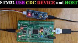
STM32 USB CDC Tutorial: Send & Receive Data via Virtual COM Port
Most STM32 tutorials use UART to talk to a PC. That works well on Nucleo and Discovery boards that have an on-board ST-Link with Virtual COM Port support. But on a custom board, a Bluepill, or any design without ST-Link, you need an external USB-to-UART adapter just to print a debug string. USB CDC eliminates that entirely.
This tutorial covers STM32 USB CDC — how to configure the USB peripheral as a Virtual COM Port in CubeMX, and how to use CDC_Transmit_FS and CDC_Receive_FS to send and receive data between STM32 and a PC. The hardware is an STM32F103 (Bluepill) connected directly via USB — no UART, no adapter. The PC sees it as a standard COM port and any serial terminal (PuTTY, Tera Term, Hercules) works out of the box.
This is a standalone tutorial. If you need USB CDC running alongside a USB Host (both device and host on the same board), see the STM32 USB CDC Device and Host tutorial.
STM32 USB CDC: How It Works
When working with STM32 microcontrollers, we often use UART to send and receive data between the board and a PC. However, STM32 also has a powerful feature called USB Communication Device Class (USB CDC). With USB CDC, your STM32 can communicate directly with a computer over USB, just like a virtual COM port, without needing a USB-to-UART converter. This makes STM32 USB communication faster, more reliable, and easier to set up for many IoT and embedded projects.
What is USB CDC (Communication Device Class)
USB CDC or USB Communication Device Class, is a standard USB protocol that lets devices act as virtual serial ports. When you enable USB CDC on STM32, your computer recognizes the board as a Virtual COM Port (VCP). This means you can use the same serial terminal software you use for UART—like PuTTY, Tera Term, or Arduino Serial Monitor—to exchange data over USB. For developers, this makes the transition from UART to USB seamless, while unlocking the benefits of direct USB communication.
USB CDC vs UART: Why Choose USB?
Traditionally, developers use UART with a USB-to-serial adapter to connect STM32 to a PC. While this works, it adds extra hardware and limits speed. By using STM32 USB CDC, you connect the board directly to your PC’s USB port. This approach removes the need for converters, reduces wiring, and offers higher data transfer rates. It also allows you to run multiple virtual COM ports if your project requires more than one channel of communication. In short, USB provides cleaner, faster, and more efficient communication than UART when working with STM32.
Features of USB CDC in STM32:
- Virtual COM Port Emulation:
Creates a virtual serial port on the PC, enabling standard serial communication without physical UART hardware. - High-Speed Data Transfer:
Supports faster data rates compared to traditional UART, limited only by USB specifications. - Plug-and-Play Support:
Works seamlessly with most operating systems (Windows, Linux, macOS) without requiring specialized drivers. - Bidirectional Data Exchange:
Enables simultaneous data transmission and reception, making it suitable for real-time communication applications.
STM32 USB CDC CubeMX Setup
Before you can start sending and receiving data with STM32 over USB, you need to configure the USB peripheral in STM32CubeMX.
Enabling the USB Device Peripheral
First, open STM32CubeMX and select your target STM32 microcontroller. In the Peripherals tab, locate and enable the USB Device (FS) or USB OTG FS peripheral, depending on your board. Make sure to choose Device Only mode, since we are using STM32 as a USB device connected to a PC.

Configuring USB as a Virtual COM Port (CDC)
Next, configure the USB device to work as a Communication Device Class (CDC). In CubeMX, go to the USB configuration settings and select CDC (Communication Device Class). This tells STM32 to act like a Virtual COM Port (VCP), making it appear as a serial port on your PC. You can also adjust endpoint sizes and buffer settings here to optimize data transfer for your application.

Setting the System and USB Clock
The Bluepill Board (STM32F103C8) has an 8Mhz oscillator on it. We will use it to clock the main system and USB peripheral as well.
First we need to enable the External High Speed (HSE) crystal.

We will use the PLL to clock the main system. The USB peripheral requires a precise 48 MHz clock to function properly. Without this, your USB CDC virtual COM port may not work, and data transmission can fail.

STM32 USB CDC Code & Results
To send data to a PC using USB CDC, we need to use specific functions provided in the STM32 USB middleware. These functions are implemented in the following file:
USB_DEVICE -> App -> usbd_cdc_if.hSending Data with CDC_Transmit_FS
Once your STM32 USB CDC is set up, you can start sending data from the microcontroller to your PC using the CDC_Transmit_FS function. This function is part of the STM32 HAL USB CDC library and makes sending messages over USB straightforward.
How CDC_Transmit_FS Works
The CDC_Transmit_FS function sends a buffer of data from your STM32 to the PC through the virtual COM port. Its basic syntax looks like this:
uint8_t CDC_Transmit_FS(uint8_t* Buf, uint16_t Len);Buf– Pointer to the data buffer you want to send.Len– Number of bytes to transmit.
When called, CDC_Transmit_FS queues the data for transmission over USB. Your PC will receive this data just like it would from a normal serial port.
Note:
The Buf can only contain Ascii characters. If you want to transmit numbers or floats, convert them to Ascii format using
sprintf.
Transmit Example Code
#include "main.h"
#include "usb_device.h"
#include "usbd_cdc_if.h"
#include "string.h"

/* Private user code ---------------------------------------------------------*/
/* USER CODE BEGIN 0 */
char *data = "Hello World from USB CDC\n";
/* USER CODE END 0 */

int main(void)
{
  HAL_Init();
  SystemClock_Config();
  MX_GPIO_Init();
  MX_USB_DEVICE_Init();   // Initialize the USB device stack

  while (1)
  {
    CDC_Transmit_FS((uint8_t *)data, strlen(data)); // Send data via USB
    HAL_Delay(1000);                      // Wait for 1 second
  }
}Verifying Output on the PC (Serial Monitor)
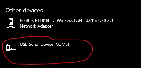
After you run your STM32 code, the PC automatically detects the board as a Virtual COM Port (VCP). This confirms that the USB CDC setup is working correctly. You can now view the data sent from your STM32 using any serial terminal software.
Note:
The STM32 dev board will be recognized by the computer only when the program is running on the board. Also make sure the USB cable is capable of data transfer.
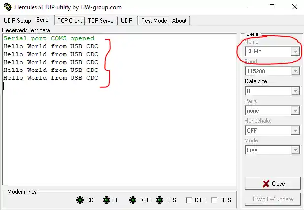
Now Open any serial monitor software (e.g., Hercules, Tera Term, or PuTTY) and select the correct COM port and you will start seeing the messages “Hello World from USB CDC” printed every second.
Receiving Data with CDC_Receive_FS
After sending data from STM32 to your PC, you often need to receive data back from the PC. The STM32 HAL library provides the CDC_Receive_FS function to handle incoming data over USB CDC. This function lets your board act like a true serial device, reading messages sent from the computer in real time.
How CDC_Receive_FS Works
The CDC_Receive_FS function is a callback that automatically executes when the PC sends data. CubeMX-generated code links this function to the USB CDC driver, so you don’t need to manage low-level USB packets manually.
Basic usage example:
uint8_t USB_RxBuffer[64]; // Buffer to store received data

static int8_t CDC_Receive_FS(uint8_t* Buf, uint32_t *Len)
{
	/* USER CODE BEGIN 6 */
	memcpy(USB_RxBuffer, Buf, *Len); // Copy received data to buffer

	USBD_CDC_SetRxBuffer(&hUsbDeviceFS, &Buf[0]);
	USBD_CDC_ReceivePacket(&hUsbDeviceFS);
	return (USBD_OK);
	/* USER CODE END 6 */
}- Buf → pointer to received data
- Len → number of bytes received
We copy the received data into our own buffer (USB_RxBuffer) so it can be used later in the application.
The lines:
USBD_CDC_SetRxBuffer(&hUsbDeviceFS, Buf);   // Set buffer for next reception
USBD_CDC_ReceivePacket(&hUsbDeviceFS); // Re-enable USB receptionare automatically generated by STM32CubeMX and must not be removed. They tell the USB stack where to store the next incoming data and re-enable the reception. Without them, the device will stop receiving data after the first packet.
Note:
We need to modify the default
CDC_Receive_FS() function in the usb_cdc_if.cextern uint8_t USB_RxBuffer[]; inside the main function to access the data stored in the received buffer.
Echo Example: Receive and Retransmit
You can combine CDC_Receive_FS with CDC_Transmit_FS to echo messages back to the PC, which is useful for testing:
static int8_t CDC_Receive_FS(uint8_t* Buf, uint32_t *Len)
{
	/* USER CODE BEGIN 6 */
	memcpy(USB_RxBuffer, Buf, *Len); // Copy received data to buffer
	CDC_Transmit_FS(Buf, *Len);

	USBD_CDC_SetRxBuffer(&hUsbDeviceFS, &Buf[0]);
	USBD_CDC_ReceivePacket(&hUsbDeviceFS);
	return (USBD_OK);
	/* USER CODE END 6 */
}This setup allows STM32 to receive any message typed on the PC and immediately send it back, confirming two-way USB communication.
Tips for Using CDC_Receive_FS
- Use a sufficient buffer – Ensure the buffer can hold the largest expected message from the PC.
- Process data quickly – Avoid long delays inside the callback to prevent USB communication issues.
- Combine with interrupts – For continuous communication, process received data in the main loop or in a separate task after copying it from the callback.
Using CDC_Receive_FS makes your STM32 USB CDC communication fully bidirectional, eliminating the need for UART while enabling real-time interaction with your PC.
USB CDC Result: Two-Way Communication Verified
The result of the above code is shown in the images below

The controller was keep transmitting “Hello World from USB CDC”. When the PC sent the data “123456789” (Represented by Pink colour on the console) to the controller, it gets stored in the buffer.
You can see the data stored in the buffer in the debugger’s Live Expression window as shown in the image above.
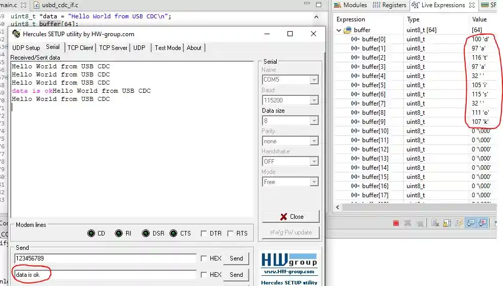
The same behavior was observed in this case as well. This time, a different set of data was transmitted, and it was successfully stored in the buffer.
Since the buffer is accessible from the main.c file, the received data can be processed further in any desired manner, such as parsing commands, logging information, or triggering specific application tasks.
USB CDC vs UART: Key Advantages
Using STM32 USB CDC instead of traditional UART offers several important benefits. It makes your PC communication faster, cleaner, and more flexible.
Faster Data Transfer Speed
USB CDC provides higher data transfer rates compared to UART. With USB, STM32 can send and receive larger amounts of data quickly, making it ideal for applications that require frequent or high-volume communication. This speed improvement helps reduce latency and ensures smoother data logging and control tasks.
Direct PC Connectivity (No USB-UART Converter Needed)
Unlike UART, USB CDC allows the STM32 to connect directly to a PC. You don’t need a USB-to-UART converter or extra wiring. The STM32 appears as a Virtual COM Port on the PC, so you can use standard serial terminal software like PuTTY, Tera Term, or Hercules. This simplifies setup and reduces hardware costs.
Reliable Bidirectional Communication
USB CDC supports full bidirectional communication, meaning you can send data from STM32 to the PC and receive data back at the same time. Unlike UART, which may require additional circuitry for multiple channels, USB CDC provides a stable and reliable two-way communication channel out of the box.
STM32 USB CDC Virtual COM Port — Video Tutorial
This video walks through the complete STM32 USB CDC setup — enabling USB Device FS in CubeMX, selecting CDC class, configuring the 48 MHz USB clock, writing CDC_Transmit_FS to send data, modifying CDC_Receive_FS to store incoming data, and verifying two-way communication in a serial terminal with the STM32F103 Bluepill.
STM32 USB CDC: Troubleshooting & FAQs
Common Issues & Fixes
Even with a correct setup, you may face some common issues when using USB CDC on STM32. Here’s how to identify and fix them.
Virtual COM Port Not Showing Up on PC
If your PC does not detect the STM32 as a Virtual COM Port:
- Check that the USB cable is working and supports data transfer (some cables are power-only).
- Ensure the USB peripheral is enabled in CubeMX.
- Verify that the USB drivers are installed on your PC.
Data Not Transmitting or Receiving Correctly
If data does not appear on the PC or seems corrupted:
- Confirm that you are using the correct COM port and settings in your terminal software.
- Make sure the STM32 code calls
CDC_Transmit_FSandCDC_Receive_FScorrectly. - Avoid sending data too quickly without checking for previous transmission completion.
Driver and Firmware Related Issues
Some problems arise due to outdated or missing drivers:
- Update your USB VCP drivers for Windows, macOS, or Linux.
- Ensure CubeMX generates the latest USB CDC firmware for your STM32.
- If using custom USB code, verify that endpoint sizes, buffer lengths, and descriptors are configured correctly.
Frequently Asked Questions
Conclusion
In this tutorial you configured STM32 USB CDC in CubeMX, set the required 48 MHz USB clock, and implemented bidirectional communication using CDC_Transmit_FS and CDC_Receive_FS — all without UART or any external adapter.
The key things to carry forward: the 48 MHz clock is non-negotiable — without it the PC will not enumerate the device. CDC_Receive_FS is a callback, not a blocking call, so process received data quickly or copy it out to a buffer for the main loop. And CDC_Transmit_FS returns USBD_BUSY if the previous transmission hasn't completed — add a check or a short retry if you're sending at high frequency.
From here you can build on top of this CDC foundation: send ADC readings, log sensor data, implement a command parser that responds to PC input, or use USB CDC as the transport layer for a custom protocol. The next tutorial in the USB series covers USB MSC (Mass Storage Class) — making STM32 appear as a USB flash drive to the PC.
Download STM32 USB CDC Project Files (F103 Bluepill)
Complete CubeIDE project for STM32F103 — includes USB CDC configuration, CDC_Transmit_FS transmit loop, modified CDC_Receive_FS callback with buffer, and echo example. Free to download — support the work if it helped you.
Browse More STM32 USB Tutorials
STM32 USB HOST MSC

STM32 USB HOST HID
Emulate STM32F103 as a MOUSE
How to use STM32 as a KEYBOARD
STM32 USB CDC Tutorial: Device and Host Example Using HAL + CubeMX


hello sir,
i want to do firmware update using the usb cdc is this possible for stm32f446re mcu
Firmware Update using CDC ? Well NO. You can use CDC for transmitting and receiving data. You can use DFU for firmware update.
If you plan on using CDC to send the binary file (Like instead of UART), then it could be done, but this would require you to carefully write a lot of code. So using DFU is much better option.
Hello Sir, hope you are doing well, i followed the steps from tutorial but the device is not showing up in com port of PC, i have tried different codes like led blink and all which works fine but the CDC doesn’t work , the code gets uploaded successfully , but no com port show on device manager . pls help.
Log output file: C:\Users\NW\AppData\Local\Temp\STM32CubeProgrammer_a05264.log
ST-LINK SN : 211405003212364D434B4E00
ST-LINK FW : V2J45S7
Board : —
Voltage : 3.19V
SWD freq : 4000 KHz
Connect mode: Under Reset
Reset mode : Hardware reset
Device ID : 0x410
Revision ID : Rev X
Device name : STM32F101/F102/F103 Medium-density
Flash size : 64 KBytes
Device type : MCU
Device CPU : Cortex-M3
BL Version : —
Opening and parsing file: ST-LINK_GDB_server_a05264.srec
Memory Programming …
File : ST-LINK_GDB_server_a05264.srec
Size : 29.15 KB
Address : 0x08000000
Erasing memory corresponding to segment 0:
Erasing internal memory sectors [0 29]
Download in Progress:
File download complete
Time elapsed during download operation: 00:00:01.887
Verifying …
Download verified successfully
Shutting down…
Exit.
Hi,
Thanks for the tenurial you have made.
please make and share another one for USB BULK TRANSFER application if it is viable for you.
many thanks
Thank you so much 🙏
I’m using a blue pill with stm32f103c8t6 using STlink-V2 when I flash the file to the blue pill the stlink disconnected and not able to debug and see the data I sent to the board.
How did you connect your blue pill board and stlink.
Very good tutorial.
Hi, how should I receive unknown length of data from usb com port?I know that such operation in uart could be done using Idle line detector. but how about usb cdc receive?
The function int8_t CDC_Receive_FS(uint8_t* Buf, uint32_t *Len) already receives the data of unknown length. Here Len is the pointer to the number of data byte received.
after I press the reset button, data is no longer received by Hercules. I had to reconnect the USB to get it working again. Is there a way to prevent that?
i am using STM32F413zh nucleo when i connect the micro-USB cable to PC there is nothing as appearance in device manager????
i connect D+ and D- in p12 and p11.
in device manage only st-link cable was showing.
what i do please help….
1. Why are you even doing this on the nucleo board ? You can simply send the data to the PC via the STlink using the UART2.
2. Nucleo STM32F413zh has one user USB at the bottom. Use it.
Salut, j’utilise un STM32H735G-DK. J’ai suivi votre tuto, et vu que les désignations de fonction diffèrent (STM32F & STM32H) j’ai du modifier le “F” de CDC_Transmit_FS par “H” ce qui m’a donné CDC_Transmit_HS. Malgré toutes mes tentatives, mon pc ne détecte pas le port vituel de mon MCU. Svp j’ai besoin d’aide . . . vous pouvez me contacter à mon adresse m.a.i.l: karimnana520 @gmail.com ou sur mon whatsapp actuel: +237 658747103
USB HS Does not supports virtual Communication. You have to use FS only
I’m using stm32f429zit6 but my board is not detected by hercule. what am i do?
if you are using the nucleo or discovery boards, make sure you connect to the USER USB, not the ST-Link
Also check if the cable supports the data transfer or not
This tutorial in Stdlibrary instead please
How recieve packet from PC
B0=254; // sync
B1 //number of variable
B2//Low byte
B3// byte
B4// byte
B5=//High Byte
Var[B1]=B2+B3<<8+B4<<16+B5<<32
If the stream fails, then in the incoming stream we look for synchrobyte 254 (skip bytes until we have received 254)
how can i transmit a HEX value instead of char?
Thanks!
just send it simply. What’s the issue?
Hai, how can we send/transmit the adc value through the usb cdc virtual comfort, I am new to stm32 ,if anyone known please help me
try sending the address to the value.
If can’t, then convert it to string and send
https://www.digikey.com/en/maker/projects/getting-started-with-stm32-working-with-adc-and-dma/f5009db3a3ed4370acaf545a3370c30c
stm32f4 ws2812b with cubeide.
That great! You can make video with NRF24L01, please!
it’s great 😍
The USB_CDC_ReceivePacket is the acknowledge of receiving. It should be called after copy the data.