Last Updated: February 6, 2026
STM32 SD Card Interface via SPI and DMA | FATFS Read & Write Example
This guide shows how to interface an SD card with STM32 using SPI and DMA, supporting SDSC, SDHC, and SDXC formats. With STM32CubeMX, HAL, and FATFS, you’ll learn how to configure SPI in polling or DMA mode, mount the card, and read/write files efficiently. Whether you’re building a STM32 SD card data logger, CSV parser, or storage module, this SPI SD card interface covers all the steps — from wiring and CubeMX setup to FATFS SD card write/read code examples.
To better understand the steps, I’ve also created a detailed walkthrough video. You can follow along with the explanations below while watching the video here:
In this tutorial we will cover how to interface the SD Card with STM32 using the SPI protocol. The library used in this tutorial also supports the use of DMA for data transfer, increasing the SD card read and write speeds.
The library supports majority of the SD Card types, that includes SDSC (Standard Capacity), SDHC (High Capacity) and SDXC (eXtended Capacity).
Recommended Tutorials:
You can also take a look at the following related tutorials:
What is an SD Card SPI Module for STM32?
An SD Card SPI Module is a compact interface board used to connect an SD or microSD card to a microcontroller (like STM32 or Arduino) via the SPI (Serial Peripheral Interface) protocol. It provides level shifting and power regulation to safely operate the card at 3.3V, while allowing 5V-tolerant microcontrollers to communicate with it. The module enables easy reading and writing of data to SD cards, making it ideal for projects involving data logging, storage, or file handling.
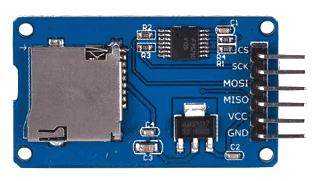
Some of its features are:
| Feature | Details |
|---|---|
| SPI Interface Support | Communicates with microcontrollers using the standard SPI protocol. |
| Voltage Level Shifting | Includes built-in resistors or ICs to step down 5V signals to 3.3V. |
| Onboard Voltage Regulator | Converts 5V input from the microcontroller to 3.3V required by SD cards. |
| Standard SD & microSD Slot | Compatible with standard SD or microSD cards for flexible usage. |
STM32 SD Card SPI Wiring (CS, SCK, MISO, MOSI)
Below is the image showing the connection between SD Card Module and STM32F103C8. I have also connected a FT232 USB-to-UART converted with the MCU. This is to send the logs to the serial monitor using the UART.
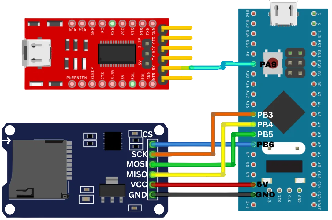
As per the image, the connection is as follows:
| Peripheral | Peripheral Pin | STM32 Pin | Function |
|---|---|---|---|
| SD Card Module | CS | PB6 | Chip Select |
| SCK | PB3 | SPI Clock | |
| MOSI | PB5 | Master Out Slave In (Data to card) | |
| MISO | PB4 | Master In Slave Out (Data from card) | |
| VCC | 5V | Power Supply | |
| GND | GND | Ground | |
| FTDI Module | TX | PA9 | UART RX (to receive data on STM32) |
Note: Only the RX from FTDI is connected in this diagram, it’s used primarily for receiving data from the STM32.
STM32CubeMX Setup for SD Card SPI Interface (F103C8 Example)
I am going to use the STM32F103C8 microcontroller for this project. We will start with the clock configuration first.
Clock Configuration
Below is the image showing the clock set up in F103C8.
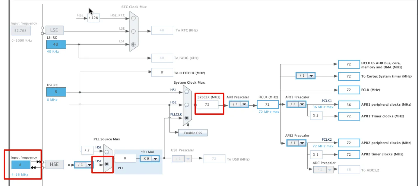
The system is clocked by the 8Mhz HSE crystal and we will run it at maximum 72Mhz.
SPI Configuration
Below is the image showing the SPI1 configuration.
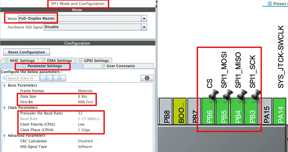
The SPI1 is configured in Full-Duplex master mode, which allows simultaneous transmission and reception of data. The parameters are configured in the default mode with 8 bits Data Size, CPOL set to Low and CPHA set to 1 Edge.
The Prescaler is set such that the Baud Rate remains around 2MBits/s. You can test the card at even higher Baud rates, I am setting it within safe limits.
The SPI Pins (PB3, PB4 and PB5) are configured with the SPI itself. We need to set the CS pin as output. The pin configuration for the CS pin is shown in the image below.
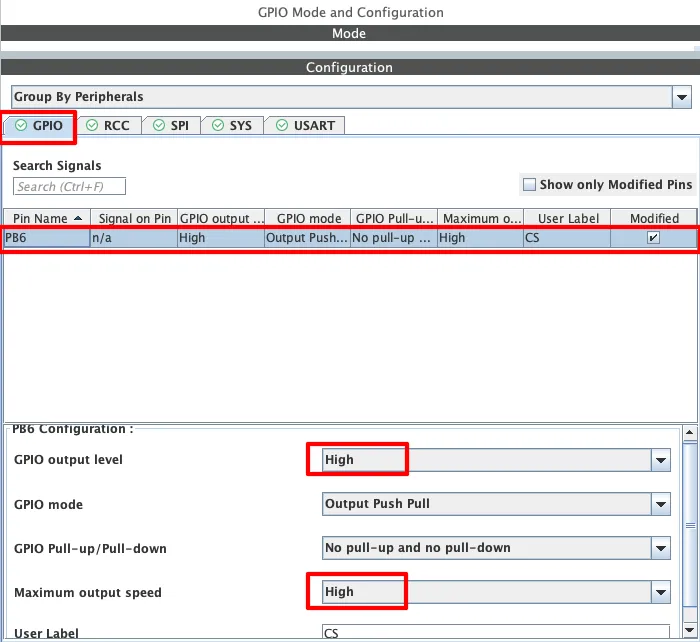
Set the Initial output level to High so that the CS pin is disabled by default. Also set the output speed to high as we need to toggle this pin at a very high rate.
If you want to use the DMA for data transfer, enable it in the DMA Settings.
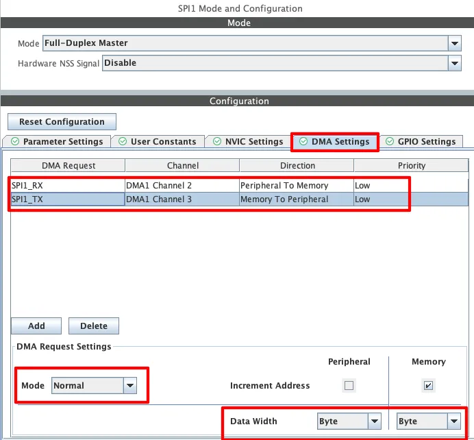
Make sure to enable the DMA for both TX and RX. The DMA Mode should be Normal and the Data width should be set to Byte.
UART Configuration
We need the UART to see the logs on the serial console. This will help us identify, if there is any issue with the library. Below is the image showing the UART configuration.
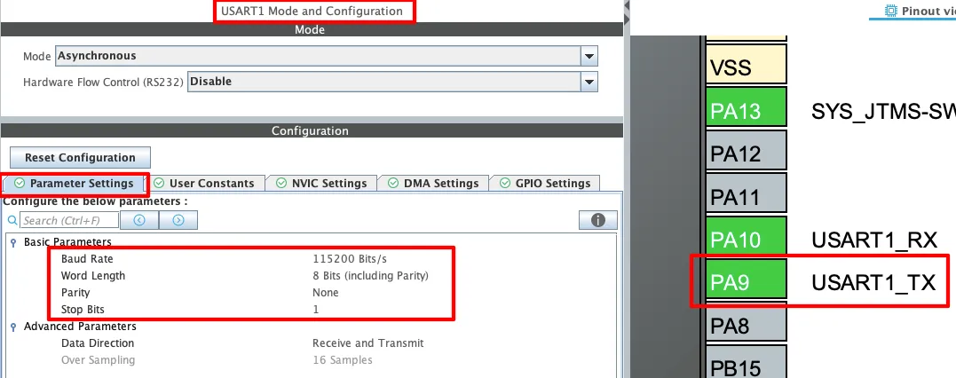
I am using the UART1 in the asynchronous mode. The default configuration is being used with the baud rate of 115200.
The pin PA9 (UART_TX) is connected to the FT232 RX pin. We do not need to receive the data from the console, so the connection of PA10 (UART_RX) is not needed.
FATFS Configuration
FATFS Middleware is needed to handle the files on the SD card. Below is the image showing the FATFS Configuration.
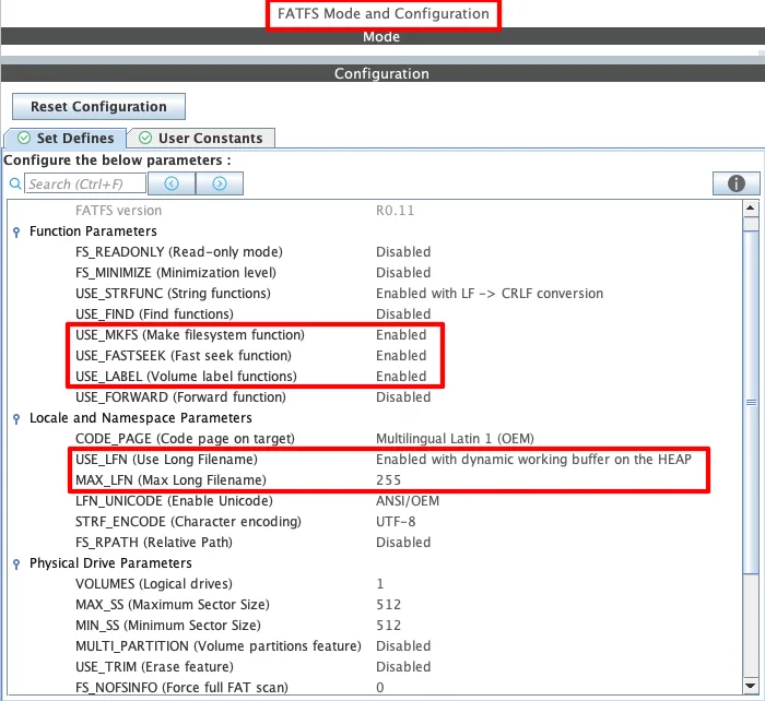
The library uses the MKFS(Make Filesystem Function) to format the SD Card (If corrupted or not FAT32). Therefore the USE_MKFS along with USE_LABEL must be enabled.
It also uses the long filenames, therefore enable the USE_LFN with a dynamic working buffer on the HEAP. This will allow us to use filenames longer than the default 8.3 format (8 chars for name and 3 for extension).
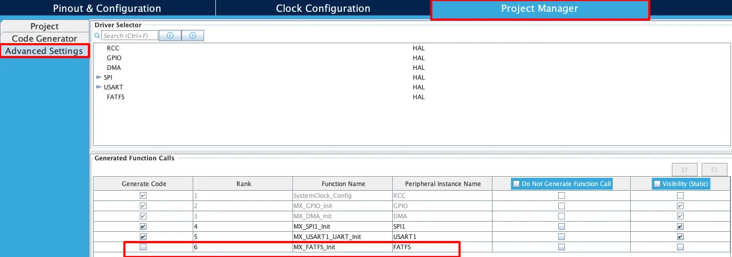
The default FATFS initialization function will link the FATFS drivers to the pre-generated drivers. We have our own drivers for FATFS which will be linked during the card initialization. Therefore we need to disable the MX_FATFS_Init function from being called in the main function.
You can do this in the project manager. Just disable the Code generation for MX_FATFS_Init.
STM32 FATFS Library for SPI SD Card Read/Write
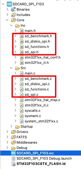
After generating the project, we need to copy the library files to the src and inc folders. The final project after copying the files looks as shown below.
The sd_spi.c file contains all the low level functions used for transmitting and receiving data from SD card using the SPI protocol. We need to define some custom variables at the beginning of this file.
/***************************************************************
 * 🔧 USER-MODIFIABLE SECTION
 * You are free to edit anything below this line
 ***************************************************************/

#define USE_DMA 1

extern SPI_HandleTypeDef hspi1;
#define SD_SPI_HANDLE hspi1

#define SD_CS_LOW()     HAL_GPIO_WritePin(CS_GPIO_Port, CS_Pin, GPIO_PIN_RESET)
#define SD_CS_HIGH()    HAL_GPIO_WritePin(CS_GPIO_Port, CS_Pin, GPIO_PIN_SET)

/***************************************************************
 * 🚫 DO NOT MODIFY BELOW THIS LINE
 * Auto-generated/system-managed code. Changes may be lost.
***************************************************************/The USE_DMA flag configures if you want to use the SPI-DMA for data transfer or not. We also need to define the SPI handleTypedef here based on the SPI instance we are using.
Then define the correct CS pin and its port, if you have not renamed the CS pin in the cubeMX.
The rest of this file should remain unchanged.
The sd_diskio_spi.c contains the FATFS drivers for the SD card. This file is basically responsible to link the SD card SPI functions to the FATFS. We do not need to modify anything in this file.
The sd_benchmark.c file is used for benchmarking the read and write speeds of the SD card. We also need to modify few things in this file.
/***************************************************************
 * 🔧 USER-MODIFIABLE SECTION
 * You are free to edit anything below this line
 ***************************************************************/

#define USE_DMA 1
#define TEST_SIZE 512000 // 500KB Test File

/***************************************************************
 * 🚫 DO NOT MODIFY BELOW THIS LINE
 * Auto-generated/system-managed code. Changes may be lost.
***************************************************************/The USE_DMA flag configures if you want to use the SPI-DMA for data transfer or not. We can modify the TEST_SIZE to change the size of the test file which is copied and read from the SD card.
The sd_functions.c file contains all the user functions for the SD card operations. The file contains functions like mount, read, write, list, etc. We do not need to modify anything in this file.
The library uses the printf function to log the data to the serial console. We will define a custom write function to route the printf data via the UART. Make sure to define the correct UART instance in the write function.
int _write(int fd, unsigned char *buf, int len) {
  if (fd == 1 || fd == 2) {                     // stdout or stderr ?
    HAL_UART_Transmit(&huart1, buf, len, 999);  // Print to the UART
  }
  return len;
}THE CODE
Inclusions
We will start by including the header files first.
/* USER CODE BEGIN Includes */
#include "sd_functions.h"
#include "stdio.h"
#include "sd_benchmark.h"
/* USER CODE END Includes */The sd_functions contains all the user functions for SD card operations. The stdio will be used by the printf function and sd_benchmark will be used for benchmarking the SD card.
Definitions
We need to define some global variables.
uint8_t bufr[80];
UINT br;The bufr array will store the data read from a file on the SD card, which we will then print on the serial console. The variable br will store the number of bytes read from the file.
List Files
Let’s test the file listing first. I have already created some files and folders on the SD card and we will retrieve them on the console.
  sd_mount();
  sd_list_files();
sd_unmount();We will first mount the SD card, then retrieve all the files from it and finally unmount the card. Below is the image showing the output of this code.
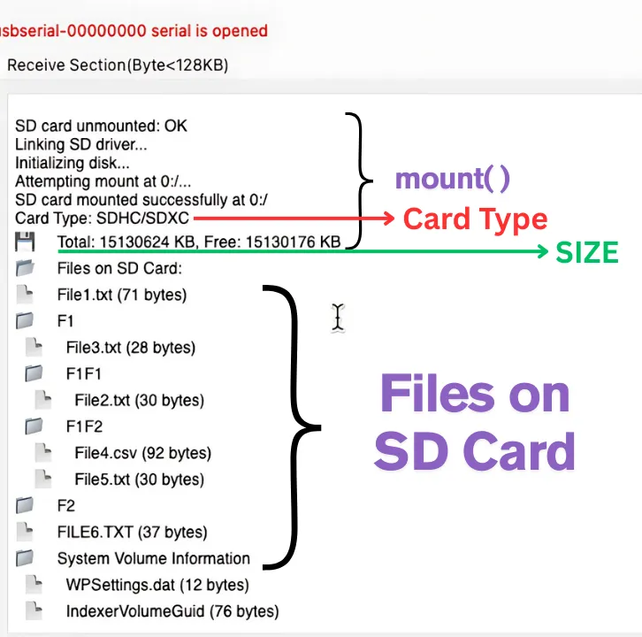
As you can see the mount was successful and the mount() function provides some details about the card like the card type (SDHC), its capacity (16GB) and Free space.
After mounting, it listed all the files and directories present on the card along with the file sizes.
Read File from SD Card (STM32 FATFS Example)
Now we will read a file from the card and print its data on the serial console.
  sd_mount();
  sd_read_file("F1/F1F2/File5.TXT", bufr, 50, &br);
  printf("DATA from File:::: %s\n\n",bufr);
sd_unmount();After mounting the card, we will read the data from the File5.txt. This file is present inside the folder F1F2, which itself is present in the folder F1.
After storing the data in the bufr array, we will print the array on the console and unmount the card.
Below is the image showing the output of this code.
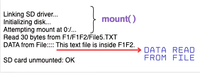
As you can see, after mounting the SD card, 30 bytes of data was read from the file5.txt. This data is then printed on the serial console.
Write File to SD Card (Create & Save Text in STM32)
Next we will test the write operation. We will create a new file and write some data into it.
  sd_mount();
  sd_write_file("FILE6.TXT", "This file is created by the cubeIDE\n");
  sd_read_file("File6.txt", bufr, 80, &br);
  printf("DATA from File:::: %s\n\n",bufr);
  sd_list_files();
sd_unmount();After mounting the card, we will write the data into the File6.txt. This file is not present in the SD card, therefore the write operation will first create the file and then write the data into it.
After writing the data, we will read it back and print the data on the console.
We will also list the files to check if the fil6.txt is present on the SD card or not.
Below is the image showing the output of this code.
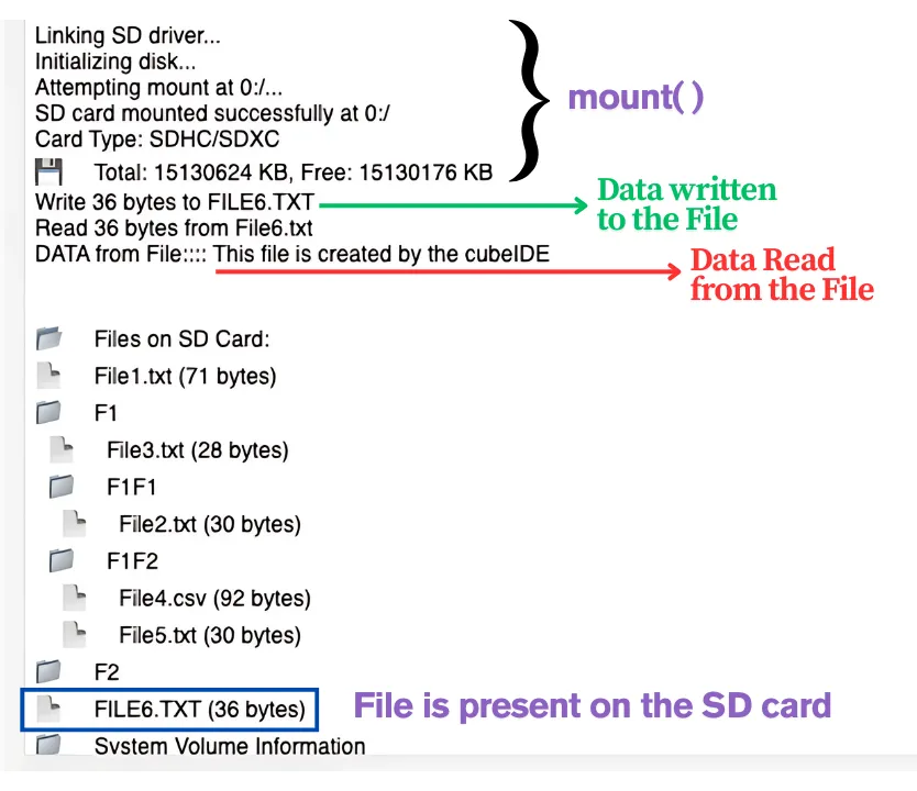
As you can see, after mounting SD Card, 36 bytes were written to File6.TXT. The data read from the file is same as what we wrote into it.
Also note that the list files shows the File6.TXT present on the root of the SD Card.
Read CSV File
Next we will read the CSV File. The library contains a function for the processing of CSV files. I already have a CSV file present in the SD Card. Below is the image showing the data inside the file.
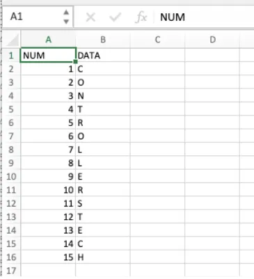
The CSV file has a total of 16 rows of data. We will read this file now.
#define max_records 20
  CsvRecord myrecords[max_records];
  int record_count = 0;
  sd_mount();
  sd_read_csv("F1/F1F2/File4.csv", myrecords, max_records, &record_count);
sd_unmount();- max_records is the maximum number of expected rows in the file.
- myrecords is the CsvRecord structure, which contains the 2 elements to store data of 2 columns.
- record_count is the actual number of rows read by the function.
After mounting the SD card, we will read data from the CSV file. The data will be stored in the myrecords structure.
Below is the image showing the output of this code.
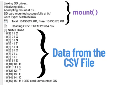
As you can see in the image, after mounting the card, the function read the data from the file correctly.
Append the File
Next we will append the data into an existing file. I will update the data to the File6.TXT created earlier.
    sd_mount();
    sd_append_file("File6.txt", "This is Appended Text\n");
    sd_read_file("File6.txt", bufr, 80, &br);
    printf("DATA from File:::: %s\n\n",bufr);
sd_unmount();After mounting the card, we will append the File6.TXT. This file should be already present in the SD card for the function to work.
We will then read the File6.TXT to get the complete data (Original Data + Appended data).
Below is the image showing the output of this code.
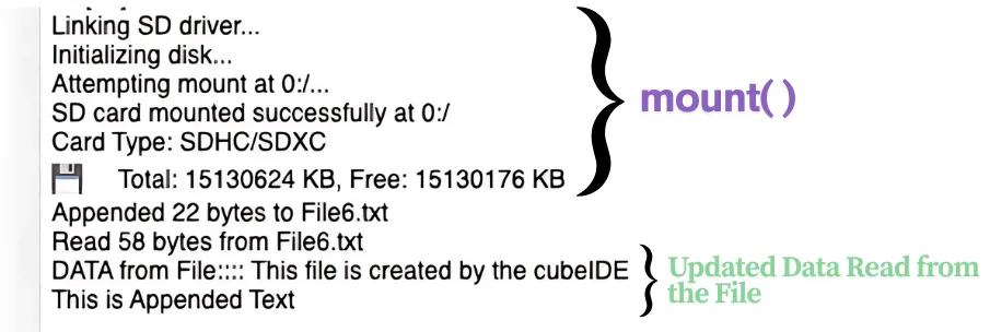
As you can see in the image above, the function appended 22 bytes to the file. Then we read 58 bytes from File6.txt. This file was originally 36 bytes and now 22 bytes are appended to it. The data read from the file is then printed on the console.
Benchmarks
The file sd_benchmark.c already contains the functions for benchmarking the SD card read and write capabilities. We just need to call the function sd_benchmark(); inside the main function.
Below is the image showing the test result when the DMA is disabled.
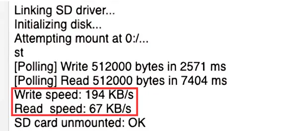
Here I am getting the write speed of 194KB/s and the read speed of 67KB/s with the Polling Mode.
Below is the image showing the test result when the DMA is enabled.
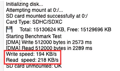
With DMA enabled, the write speed remain the same 194KB/s but the read speed increases drastically 218KB/s.
STM32 SPI vs DMA for SD Card – Performance Benchmarks
In STM32 SD card interfaces, you can choose between SPI polling and DMA modes.
Here’s how they differ:
| Mode | Write Speed (KB/s) | Read Speed (KB/s) | Notes |
| Polling | 194 | 67 | Simpler, easy to debug |
| DMA | 194 | 218 | Faster reads, better for large files |
Use DMA mode for higher throughput, especially in data logging or real-time applications.
This STM32 SD card interface using SPI and DMA gives you full control over storage operations using FATFS. You’ve learned how to read, write, append, and parse CSV files, benchmark performance, and configure CubeMX for optimal SPI/DMA settings. Whether you’re building a data logger, CSV parser, or SD-based storage, this HAL-based solution is robust, fast, and extendable.

Hallo ich habe einen Nucleo H753ZI und habe alles genau so gemacht wie sie. Allerdings bekomme ich immer den fehler, disk_init failed 0x01 . ich habe eine san disk Ultra 32GB auf Fat32 formatiert . Ist ihnen da ein problem bekannt oder können sie mir helfen?
Yeah, I have the same problem on H755, with a card i succesfully read from an Arduino, any solution?
i hav compilation error on res = f_mkfs(sd_path, 1, 0); // too fiew argument to function ‘f_mkfs’
It depends on the Fatfs version. Your mcu might be using the newer version. Try this
BYTE work[4096]; // working buffer, size must be >= 4 KB
FRESULT res = f_mkfs(sd_path, 1, 0, work, sizeof(work));
These tutorials are amazing, not just this one but in general the tutorials on the site. Thank you!