Last Updated: March 23, 2026
GLCD 128×64 ST7920 interfacing with STM32
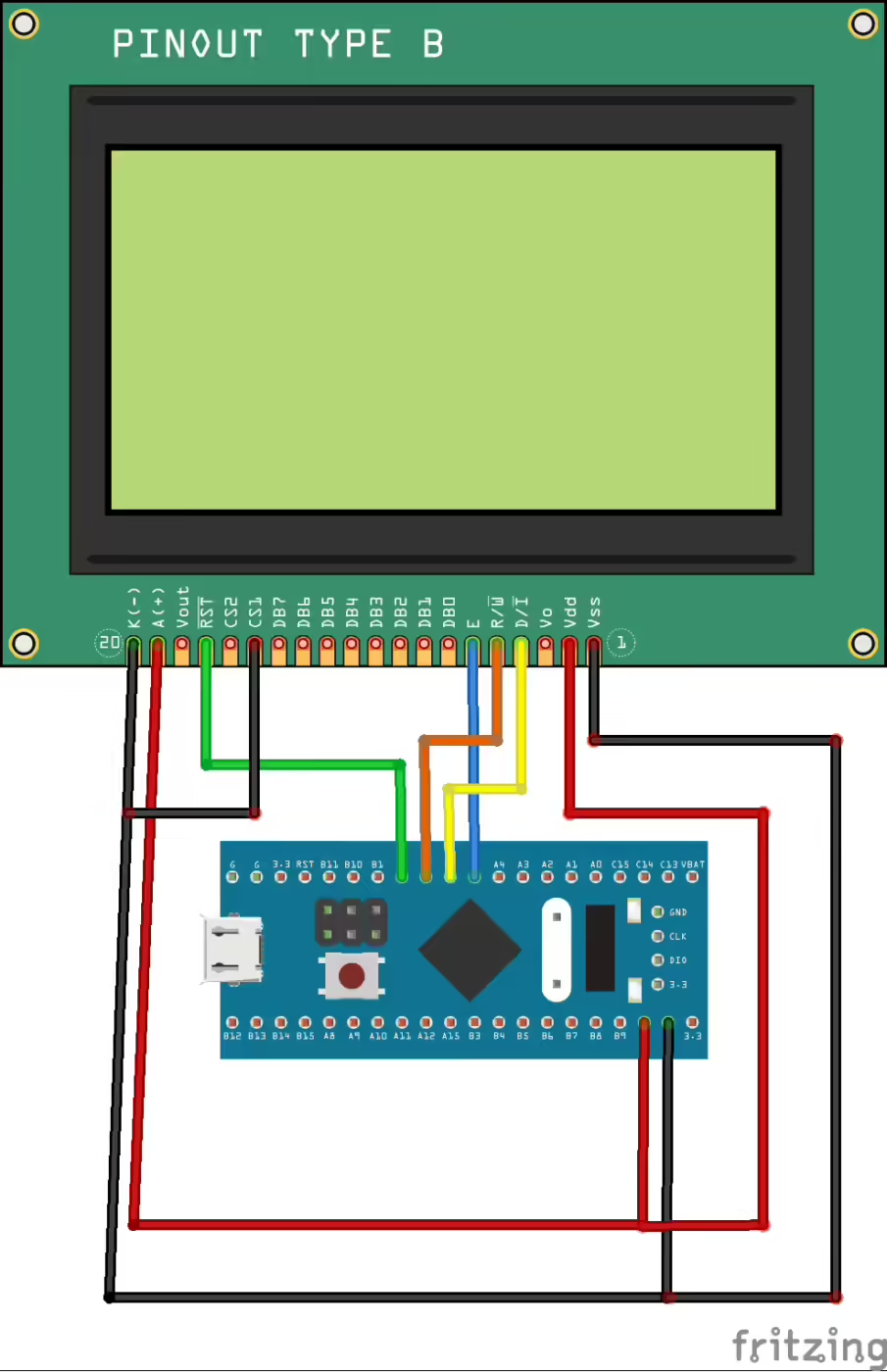
Today in this tutorial, we will interface ST7920 GLCD (128×64) display with STM32 using the Serial mode. This way we only have to use 4 pins from the microcontroller to control the entire display.
We will start with displaying simple texts, than we will look into some bitmaps and finally we will draw some shapes on the LCD. I am using STM32F103C8 microcontroller.
VIDEO TUTORIAL
You can check the video to see the complete explanation and working of this project.
Setup
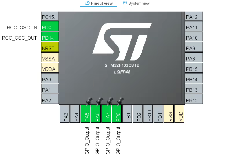
I will start this tutorial by setting up the CubeMx. In Cube Mx, for the connection purpose, we only need to select 4 pin as output as shown below
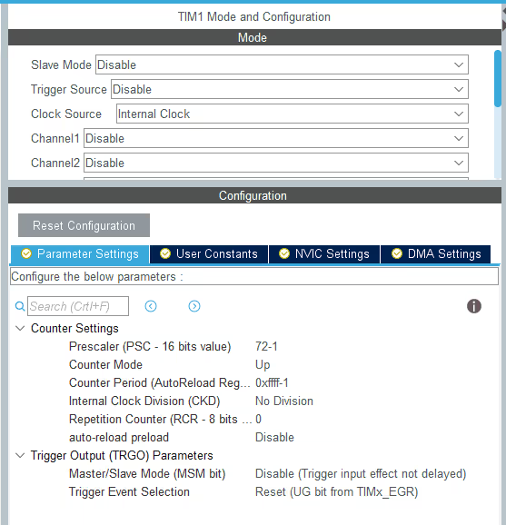
Also some of the delays will be required in the microseconds, and so, I will use the TIMER 1 to create delays in microseconds. The setup is shown below. I already did a tutorial on this. You can check it HERE
This is all the setup, that is needed for the ST7920. Let’s see some functions that we are going to use to interface this display.
Some Insight into the CODE
void SendByteSPI(uint8_t byte)Sends a byte to the MOSI / SID Pin. This is Just like How the SPI transfers the data.
Sending Command
void ST7920_SendCmd (uint8_t cmd)
{

	HAL_GPIO_WritePin(CS_PORT, CS_PIN, GPIO_PIN_SET);  // PUll the CS high

	SendByteSPI(0xf8+(0<<1));  // send the SYNC + RS(0)
	SendByteSPI(cmd&0xf0);  // send the higher nibble first
	SendByteSPI((cmd<<4)&0xf0);  // send the lower nibble
	delay_us(50);

	HAL_GPIO_WritePin(CS_PORT, CS_PIN, GPIO_PIN_RESET);  // PUll the CS LOW

}According to the datasheet of ST7920, In order to send a command to the display, We need to perform the following operations:-
1. Pull the CS Pin HIGH
2. Send the Synchronizing byte (0xF8) along with R/W and RS
3. Send the Higher command Byte
4. Send the Lower command Byte
5. Pull the CS Pin LOW to end the transfer
Sending Data
void ST7920_SendData (uint8_t data)
{
	HAL_GPIO_WritePin(CS_PORT, CS_PIN, GPIO_PIN_SET);  // PUll the CS high

	SendByteSPI(0xf8+(1<<1));  // send the SYNC + RS(1)
	SendByteSPI(data&0xf0);  // send the higher nibble first
	SendByteSPI((data<<4)&0xf0);  // send the lower nibble
	delay_us(50);
	HAL_GPIO_WritePin(CS_PORT, CS_PIN, GPIO_PIN_RESET);  // PUll the CS LOW
}Data is also sent in the same manner as the command, except the RS will be a ‘1’. Following are the operations:-
1. Pull the CS Pin HIGH
2. Send the Synchronizing byte (0xF8) along with R/W and RS
3. Send the Higher data Byte
4. Send the Lower data Byte
5. Pull the CS Pin LOW to end the transfer
Initializing Display
void ST7920_Init (void)
{
	HAL_GPIO_WritePin(RST_PORT, RST_PIN, GPIO_PIN_RESET);  // RESET=0
	HAL_Delay(10);   // wait for 10ms
	HAL_GPIO_WritePin(RST_PORT, RST_PIN, GPIO_PIN_SET);  // RESET=1

	HAL_Delay(50);   //wait for >40 ms


	ST7920_SendCmd(0x30);  // 8bit mode
	delay_us(110);  //  >100us delay

	ST7920_SendCmd(0x30);  // 8bit mode
	delay_us(40);  // >37us delay

	ST7920_SendCmd(0x08);  // D=0, C=0, B=0
	delay_us(110);  // >100us delay

	ST7920_SendCmd(0x01);  // clear screen
	HAL_Delay(12);  // >10 ms delay


	ST7920_SendCmd(0x06);  // cursor increment right no shift
	HAL_Delay(1);  // 1ms delay

	ST7920_SendCmd(0x0C);  // D=1, C=0, B=0
    HAL_Delay(1);  // 1ms delay

	ST7920_SendCmd(0x02);  // return to home
	HAL_Delay(1);  // 1ms delay

}To initialize the display, we have to follow some sequence of command. And they are mentioned below:
1. Reset the display and wait for more than 40 ms
2. Send the Function Set command and wait for more than 100 us
3. Send the Function Set command and wait for more than 37 us
4. Send the Display ON/OFF Control command and wait for more than 100 us
5. Send the Display Clear command and wait for more than 10 ms
6. Send the Entry Mode set command and this will end the initialization of the display.
Graphic Mode
void ST7920_GraphicMode ()
{
  ST7920_SendCmd(0x30);  // 8 bit mode
  HAL_Delay (1);
  ST7920_SendCmd(0x34);  // switch to Extended instructions
  HAL_Delay (1);
  ST7920_SendCmd(0x36);  // enable graphics
  HAL_Delay (1);
}To enable the Graphic mode, we have to
-> Switch to Extended Instruction Set
-> Enable the Graphics
Note that we have to perform both of these operations in separate commands as according to it is mentioned in the datasheet.
Drawing Bitmaps
void ST7920_DrawBitmap(const unsigned char* graphic)
{
	uint8_t x, y;
	for(y = 0; y < 64; y++)
	{
		if(y < 32)
		{
			for(x = 0; x < 8; x++)	/ Draws top half of the screen.
			{
                 		// In extended instruction mode, vertical and horizontal coordinates must be specified before sending data in.
				ST7920_SendCmd(0x80 | y);	// Vertical coordinate of the screen is specified first. (0-31)
				ST7920_SendCmd(0x80 | x);	// Then horizontal coordinate of the screen is specified. (0-8)
				ST7920_SendData(graphic[2*x + 16*y]);	// Data to the upper byte is sent to the coordinate.
				ST7920_SendData(graphic[2*x+1 + 16*y]);	// Data to the lower byte is sent to the coordinate.
			}
		}
		else
		{
			for(x = 0; x < 8; x++)	// Draws bottom half of the screen.
			{
                           // Actions performed as same as the upper half screen.
			   ST7920_SendCmd(0x80 | (y-32));// Vertical coordinate must be scaled back to 0-31 as it is dealing with another half of the screen.
			  ST7920_SendCmd(0x88 | x);
			  ST7920_SendData(graphic[2*x + 16*y]);
			  ST7920_SendData(graphic[2*x+1 + 16*y]);
			}
		}

	}
}In order to draw a bitmap, we need to draw on the two half of the screen. First upper half and than the lower half.
To draw, first set the coordinate of the Y axis and than the coordinate of the X axis.
After the coordinates are set, send the upper byte of the data and than the lower byte.
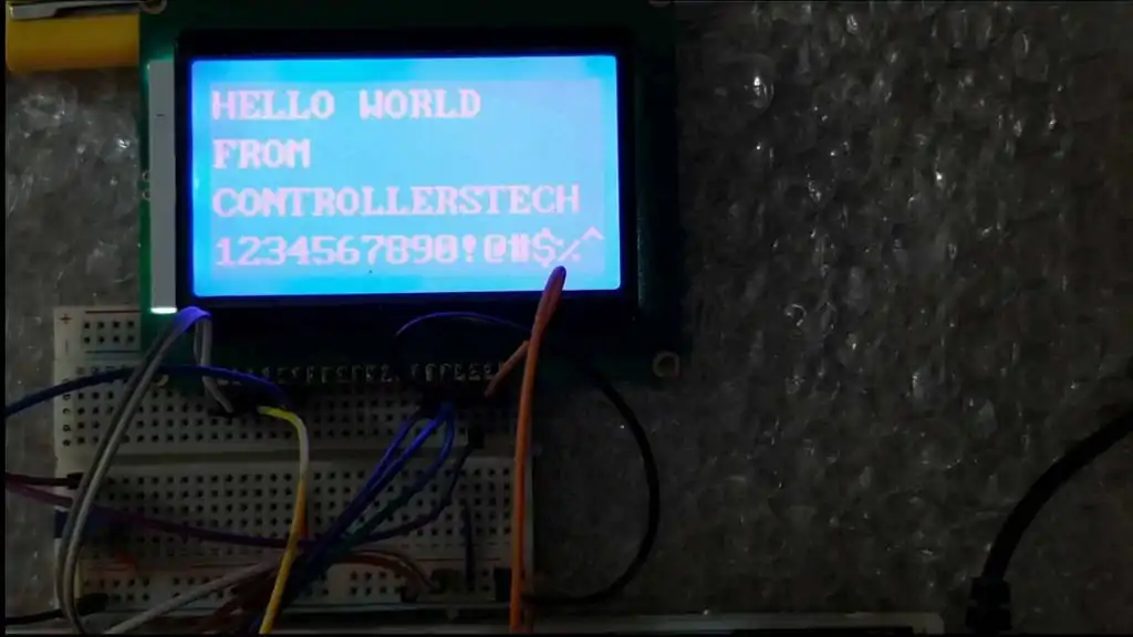
RESULT

how to set cursor position at particular row and column
Can we display character other than ASCII? I want to display character of language other than english. Please sugges.t
Hello! there’s a way to rotate 180 degrees the LCD matrix?? i devenloped a project but didnt notice that i made a 3d case on the wrong direction, and now i cant print anoter case.
Hi, I want to clear pixel. What I have to do?
Pls help me
Just want to share one experience I had.
I came here because I had trouble with my display and couldn’t get it working properly.
I used the default SPI mode that CubeIDE had given me during program creation and it seemed that certain data wouldn’t work properly. I was getting areas where I the display ram was not affected.
I noticed that the SPI was a roll your own type, so I thought maybe the SPI mode was wrong in my setup so I changed it to the following
CPOL=Low
CPHA=2 Edge
It works now so if anyone comes here who has problems if they have used the SPI peripheral, then maybe this can work for you
Hello. Will this program work with stm32f446re – 180MHz?
Hello everyone!
I tried at least 4 weeks running this program in the STM32F108 with the LCD 20 x 4 ( type is 12864 V 2.0 ) but the LCD doesn’t show anything!! When I put voltage on or reset the systems, the LCD only flashes one time. I used use CubeIDE, not CubeMX, but think so that is not make any sense make program wrong way….
Does somebody else this kind of problems? What should be done for timings?
One correction: STM32F103C8 is model of card.
Hi Ake,
Yeah I’ve got the same problem. I would appreciate it if you could tell me what you did finally to fix it.
Tnx
Can you make Nokia 5110 LCD example?
ST7920_DrawBitmap(image);
what is image? int or char
char
Can change font size?
how can i fix this error?
Error: L6200E: Symbol image multiply defined (by st7920_serial.o and main.o).
which symbol ?
uint8_t image[(128 * 64)/8];
This is my problem too. I work with keil software
Not enough information to list image symbols.
Not enough information to list load addresses in the image map.
I don’t know how to handle it
remove that uint8_t image from serial.h and put it in the serial.c file.
can i use this library for jhd12864 glcd ?
can i use this library for jhd12864 lcd
How to display wifi scanning gif on lcd with stm32.please suggest me
How do I set Pixels of lcd to make semicircle. Actually I want to make Wifi graphics over LCD,& reset pixels after high strength vice versa.
look for ADAfruitgfx.c and use the function from there, if available
Also Done this but after completing one loop. it only display large triangle actually small triangles overlap over large triangle,
Im also try with increasing delay, but it only display large triangle.Please help me.
while( i < 10)
{
ST7920_GraphicMode(1);
DrawFilledTriangle(60,60,68,60,64,64);// min Triangle Values
ST7920_Update();
HAL_Delay(1000);
DrawFilledTriangle(40,40,88,40,64,64);// mid Triangle Values
ST7920_Update();
HAL_Delay(1000);
DrawFilledTriangle(20,20,108,20,64,64);// Max Triangle Values
ST7920_Update();
HAL_Delay(1000);
ST7920_Clear();
HAL_Delay(1000);
i++;
}
try without the large triangle and see if others print.
ST7920_GraphicMode(1); remove this. as it’s already in the graphic mode..
I m also Try with this changes , in 1st loop it display perfect but in second loop it only prints large or medium which is greater than small triangle.
Hi Sir, I have a question regarding your library ,
when Im using draw filled triangle in loop from increasing to decreasing order ,It doesnt display smaller filled triangle, only display large triangle, Actually its Clear_St7920 issue, How to solve this problem, Here is my code
while(uint8_t i<10)
{
ST7920_GraphicMode(1);
DrawFilledTriangle(60,60,68,60,64,64);// min searching Values
ST7920_Update();
HAL_Delay(1000);
DrawFilledTriangle(40,40,88,40,64,64);// mid searching Values
ST7920_Update();
HAL_Delay(1000);
DrawFilledTriangle(20,20,108,20,64,64);// Max searching Values
ST7920_Update();
HAL_Delay(1000);
ST7920_GraphicMode(0);
ST7920_Clear();
HAL_Delay(1000);
i++;
}
don’t change the mode before clearing display
Also Done this but after completing one loop. it only display large triangle actually small triangles overlap over large triangle,
Im also try with increasing delay, but it only display large triangle.Please help me.
while( i < 10)
{
ST7920_GraphicMode(1);
DrawFilledTriangle(60,60,68,60,64,64);// min Triangle Values
ST7920_Update();
HAL_Delay(1000);
DrawFilledTriangle(40,40,88,40,64,64);// mid Triangle Values
ST7920_Update();
HAL_Delay(1000);
DrawFilledTriangle(20,20,108,20,64,64);// Max Triangle Values
ST7920_Update();
HAL_Delay(1000);
ST7920_Clear();
HAL_Delay(1000);
i++;
}
.
Hello, would this be compatible for an STM32L432KC. If yes, then how would you initialise the display?
I used the code for SINDA SDGB12864-02 graphical LCD but it is not showing any DATA on LCD since I do all needful steps to do in stm32f030r8t6 Evaluation board.
I am using Keil v5 for coding.
Can anyone provide me the solution to use this code with the LCD I had?
Hello, in the upper left corner are some randomly set /reset pixel. (in graphical mode) I have the same issue. Does somebody found the reason?
Hi
Code work’s fine on my stm32103c8t6, i’m using stm32cubeide
How i can add & print custom character?
Hi, I step over to use only graphical mode. ther any pixcel can be set/reset. Many font are possible or own chars.
look at:
https://www.mikrocontroller.net/topic/54860
That was very helpful
Hello, in the left upper corner are sone random set/reset Pixel – in graphical mode. Did you found the reason? I habe the Sam Problem.
hello guy. Thanks your document very much. but I have a question. I didnt use STM32f1. I used STM32f030C8, and it didnot work. I modified delay function in F0 because F0 on ly have 8M HSI, to create 1us delay. But it seem didnt work. Can you give me any idea?
void SystemClock_Config(void)
{
RCC_OscInitTypeDef RCC_OscInitStruct = {0};
RCC_ClkInitTypeDef RCC_ClkInitStruct = {0};
/** Initializes the CPU, AHB and APB busses clocks
*/
RCC_OscInitStruct.OscillatorType = RCC_OSCILLATORTYPE_HSI;
RCC_OscInitStruct.HSIState = RCC_HSI_ON;
RCC_OscInitStruct.HSICalibrationValue = RCC_HSICALIBRATION_DEFAULT;
RCC_OscInitStruct.PLL.PLLState = RCC_PLL_NONE;
if (HAL_RCC_OscConfig(&RCC_OscInitStruct) != HAL_OK)
{
Error_Handler();
}
/** Initializes the CPU, AHB and APB busses clocks
*/
RCC_ClkInitStruct.ClockType = RCC_CLOCKTYPE_HCLK|RCC_CLOCKTYPE_SYSCLK
|RCC_CLOCKTYPE_PCLK1;
RCC_ClkInitStruct.SYSCLKSource = RCC_SYSCLKSOURCE_HSI;
RCC_ClkInitStruct.AHBCLKDivider = RCC_SYSCLK_DIV8;
RCC_ClkInitStruct.APB1CLKDivider = RCC_HCLK_DIV2;
if (HAL_RCC_ClockConfig(&RCC_ClkInitStruct, FLASH_LATENCY_0) != HAL_OK)
{
Error_Handler();
}
}
static void MX_TIM1_Init(void)
{
/* USER CODE BEGIN TIM1_Init 0 */
/* USER CODE END TIM1_Init 0 */
TIM_ClockConfigTypeDef sClockSourceConfig = {0};
TIM_MasterConfigTypeDef sMasterConfig = {0};
/* USER CODE BEGIN TIM1_Init 1 */
/* USER CODE END TIM1_Init 1 */
htim1.Instance = TIM1;
htim1.Init.Prescaler = 1-1;
htim1.Init.CounterMode = TIM_COUNTERMODE_UP;
htim1.Init.Period = 0xffff-1;
htim1.Init.ClockDivision = TIM_CLOCKDIVISION_DIV1;
htim1.Init.RepetitionCounter = 0;
htim1.Init.AutoReloadPreload = TIM_AUTORELOAD_PRELOAD_DISABLE;
if (HAL_TIM_Base_Init(&htim1) != HAL_OK)
{
Error_Handler();
}
sClockSourceConfig.ClockSource = TIM_CLOCKSOURCE_INTERNAL;
if (HAL_TIM_ConfigClockSource(&htim1, &sClockSourceConfig) != HAL_OK)
{
Error_Handler();
}
sMasterConfig.MasterOutputTrigger = TIM_TRGO_RESET;
sMasterConfig.MasterSlaveMode = TIM_MASTERSLAVEMODE_DISABLE;
if (HAL_TIMEx_MasterConfigSynchronization(&htim1, &sMasterConfig) != HAL_OK)
{
Error_Handler();
}
/* USER CODE BEGIN TIM1_Init 2 */
/* USER CODE END TIM1_Init 2 */
}
There is external crystal on F030c8. But even if you have used HSI, it should be okay.
while doing the clock setup, in the HCLK, type 48 and hit enter
Now select any timer for the delay purpose, use prescalar as 48-1, and ARR as 0xffff-1