DAC in STM32
DAC stands for Digital to Analogue converter, and as the name suggests, it converts the Digital signal to Analogue form. Today in this tutorial, I will walk you through some basic DAC working in STM32. I will be using STM32F446RE controller with CubeIDE
VIDEO TUTORIAL
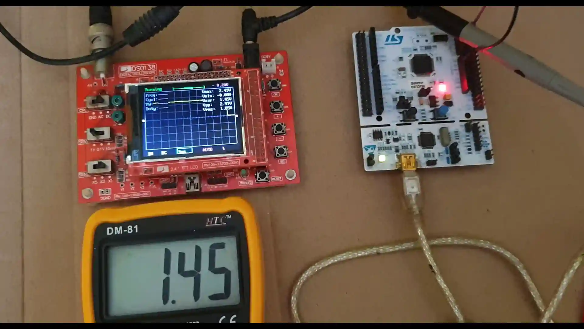
You can check the video to see the complete explanation and working of this project.
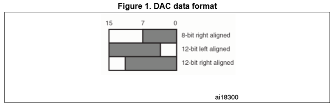
Data Format
As shown in Figure below, the DAC accepts data in three integer formats: 8-bit (the LS Byte of the data hold register), 12-bit right aligned (the twelve LS bits of the data hold register) and 12-bit left aligned (the twelve MS bits of the data hold register). In this tutorial I will use the 12 bit Right Aligned data format.
CubeMx Setting
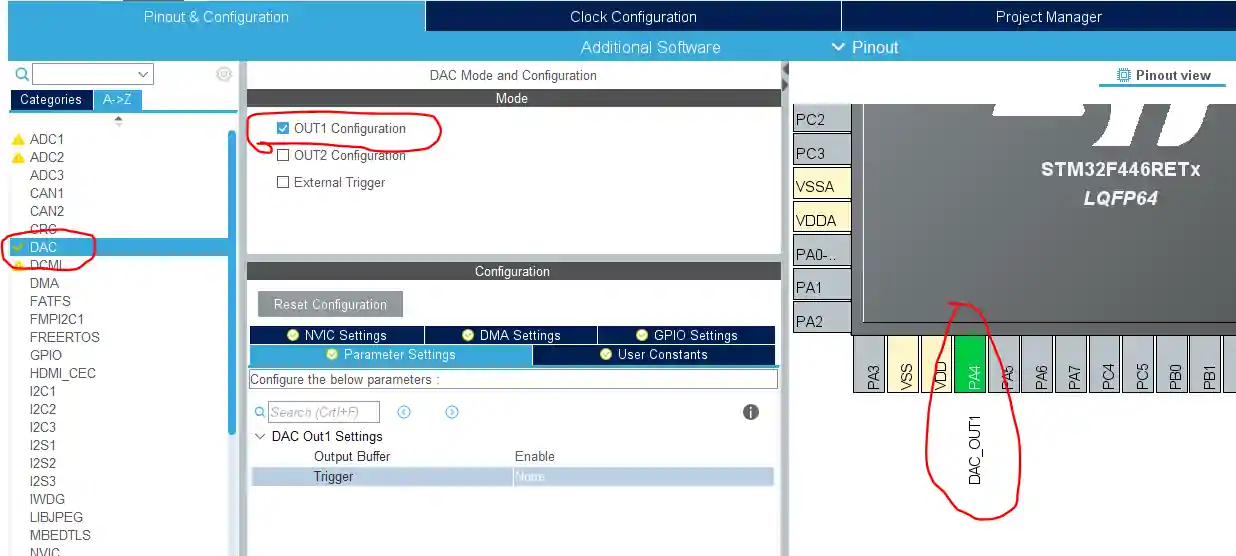
As shown in the figure above, the Out1 config is selected, and that selects the pin PA4 as the DAC_OUT pin. Also note that output buffer is enabled, and the Trigger is disabled for now.
This is all the setup we require at the moment. Setup the clock, and generate the project.
Some Insight into the CODE
float val = 1.2;
uint32_t var;In the main.c file, first I am going to define a float type variable called val. I am assigning a value of 1.2 to it. This is going to be the output voltage that we want on the pin.
Typically in normal digital form, the voltage on the pin can either be 0, or 3.3v. But with the DAC, we will vary the output on the pin in analogue form.
uint32_t var = (uint32_t)(val*4096)/3.3;Variable var stores the digital value after we convert it from the analogue form. The analogue variable, val, is being multiplied to 4096, because I am using 12 bit resolution. Also note that 3.3 is the reference voltage (Vref).
Now It’s time to start the DAC, and write this value to the pin.
I am increasing the voltage on the pin every 500 ms. You can observe this in the video at the end of the post.
while (1)
{
 var = val*(4096)/3.3;
 HAL_DAC_SetValue(&hdac, DAC_CHANNEL_1,
 DAC_ALIGN_12B_R, var);
 val += 0.5;
 HAL_Delay(2000);
 if (value>3) value=0.2;
}
Sine wave Generation
As of now, we have produced an analogue signal of varying voltage on the pin PA4. Next, we are going to produce a sine wave at the pin. First, we have to go through some setup in the cubemx again. Below is my setup
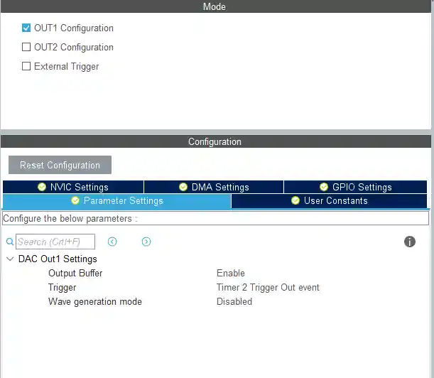
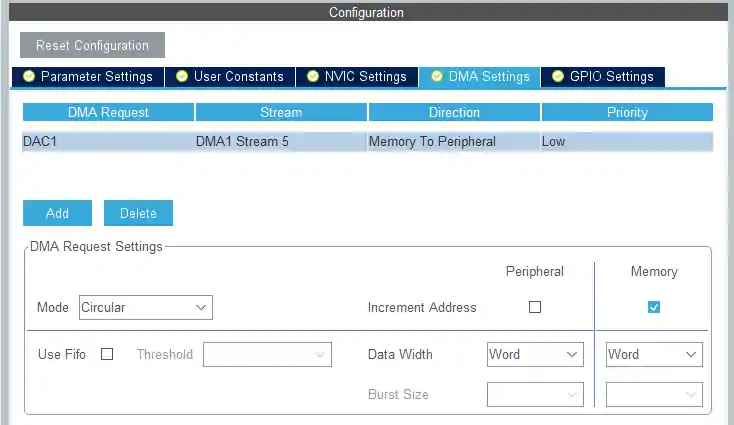
This time, I have enabled the trigger from Timer 2, and also turned on the DMA. So that the processor can be used for other purposes. As the Timer 2 is enabled for the generation of the wave, i need to set up the Timer 2.
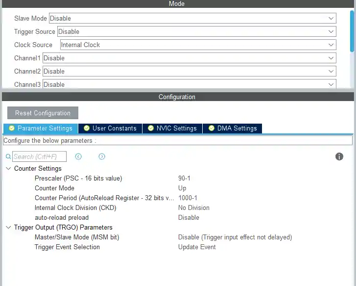
Timer 2 clock in my case is 90 MHz, and that’s why I am using a prescalar of 90. The clock will be divided by this value giving a total of 1 MHz frequency. The ARR value is 1000. This will further divide the clock, and now I have a frequency of 1000 Hz. This is the frequency of the TIMER 2 right now. The sine wave frequency also depends on the number of samples, that we are going to take. I will explain that in a while.
Let’s take a look at the code now.
#include "math.h"
.......
uint32_t sine_val[100];
#define PI 3.1415926
void calcsin ()
{
	for (int i=0; i<100; i++)
	{
		sine_val[i] = ((sin(i*2*PI/100) + 1)*(4096/2));
	}
}I have included math.h, so that we can use the sine function.
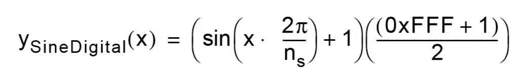
We need to generate the digital values of sine function now. calcsin function will do that. I am taking 100 samples for better accuracy. The formula I have used here, is defined in the DAC document provided by ST. The picture is shown below.
Now, talking about the frequency of the sine wave. According to this document, the frequency is given by the formula below.
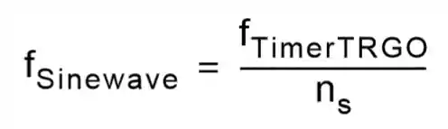
Remember the Timer frequency in our case was 1000 Hz, and we are taking 100 samples here. So, the frequency of the sine wave will be 1000/100 = 10 Hz.
HAL_TIM_Base_Start(&htim2);

calcsin();
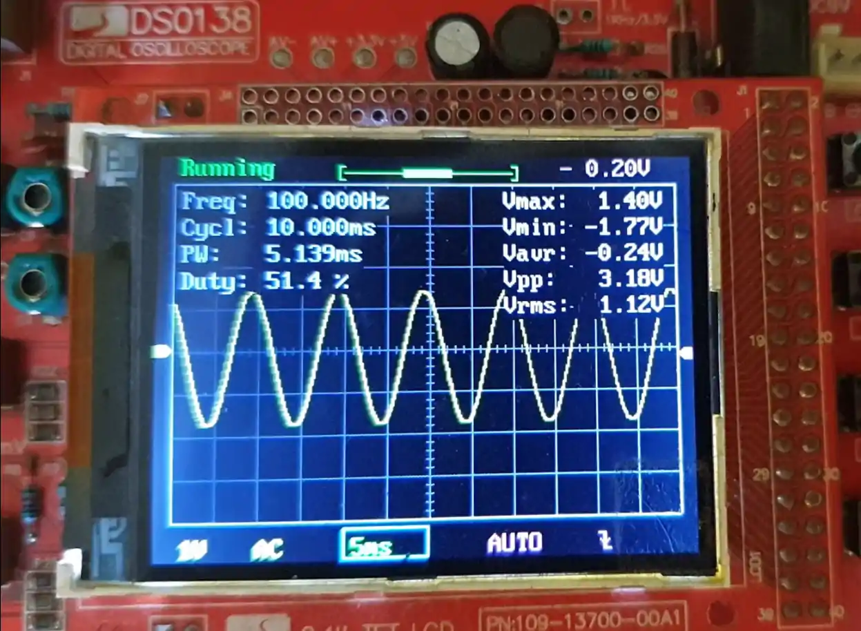
HAL_DAC_Start_DMA(&hdac, DAC1_CHANNEL_1, sine_val, 100, DAC_ALIGN_12B_R);Inside the main function, first we need to start the Timer, and than call for the function calcsin, so that the conversion can take place. Now, we will start the DAC with DMA. And that’s it, you can see the generated sine wave in the picture below.
You can control the frequency of this wave by either adjusting the TIMER parameters, or by changing the number of samples. For more details, check out the video at the end.


i wanna use dma dac in freertos dont work
the DOR value is getting updated , but i am unable to see the dac output of stm32 either in multimeter or oscilloscope.I have connectedpPA_4 to output
In the first part of the tutorial the initialisation code is omitted, you need to add the following line at the start of the code (AKA USER CODE BEGIN 2):
It cuts off the upper half of the sine. 🙁
How do we change the max and min heights of the sine-wave
you can multiply some number for example y=asin(x).
here “a” is the amplitude. But remember doin this means you are changing the voltage output from the pin and if the pin only supports 3.3V max, you can’t go higher than that.
you might need to use some amplifier for the purpose.
You may also take a look at the STM32F7 DAC TUTORIAL available on:
https://www.researchgate.net/publication/354022135_STM32_DAC_TUTORIAL_with_application_to_system_identification
Nice tutorial, can I generate a two sine wave simultaneously on DAC1 with TIM2 and on DAC2 TIM4 ?
You can, but how will you send them. At one particular time you can send only one set of data right..
But My requirement is generate two sinewave on DAC1 & DAC2 simultaneously.
On DAC1 , it will 8Khz.
On DAC2, it will 10 khz.
Wave on time and Off Will be same. now i need a help. is their any useful tutorial, how i can do this ?
use dma in circular mode
hello Sir, I want to set sinewave ON time for 50ms and OFF sinewave for 50ms,In STM32 the DAC is 12 bit, so the mid value is 2048.
so during OFF time, Can I use this function ?
see below
HAL_DAC_SetValue(&hdac,DAC_CHANNEL_1,DAC_ALIGN_12B_R,sine_val[0]);
HAL_TIM_Base_Stop(&htim6);
thanks In Advance!!!!
thanks, great tutorial, I found the 4096 amplitude in the sine calc gave me glitchy wave-tops, 4094 fixed them.
Hi,
Your text above says “The ARR value is 1000” but inside the .ioc project I see this is actually 100 (well actually 100-1).
The code runs OK but I’m confused by this discrepancy…
I might have changed it, while showing in the video that changing ARR changes the frequency..
thks for sharing, nice job!