Home ▸ STM32 Tutorials ▸
Updated On: February 12, 2026
How to Create Microsecond Delay in STM32 Using HAL Timer
When working with STM32 microcontrollers, we often need precise delays for tasks like generating waveforms, controlling sensors, or handling communication protocols. The commonly used HAL_Delay() function only provides millisecond delays, which is not enough for applications that require microsecond accuracy.
In this tutorial, we will learn how to create microsecond delay in STM32 using the hardware timer. We’ll configure the timer in CubeMX, write a delay_us function, and verify the output with a simple test. By the end of this guide, you’ll be able to implement accurate microsecond delays in your STM32 projects.
Why Do We Need Microsecond Delay in STM32?
Delays are an important part of many embedded projects. In STM32, we often need very short and accurate delays for tasks like reading sensors, generating waveforms, or controlling communication protocols. A simple millisecond delay is not always enough. Therefore, we must use a method that allows us to create a microsecond delay in STM32.
Limitation of HAL_Delay
The HAL_Delay() function in STM32 works with the SysTick timer. This timer runs at 1ms resolution, which means it can only provide delays in milliseconds. If you try to use it for smaller delays, like 10µs or 100µs, it will not work correctly. As a result, HAL_Delay() is not suitable when your project requires precise timing in microseconds.
Applications Requiring Microsecond Precision
Many real-world applications need microsecond-level accuracy. For example:
- Communication protocols like One-Wire or custom serial data transfer need microsecond timing.
- Sensor interfaces such as ultrasonic sensors require accurate delays to measure distance.
- PWM signal generation or waveform creation needs precise control of ON and OFF times.
- High-speed data sampling often depends on accurate microsecond delays.
Because of these cases, using a timer-based delay_us function in STM32 is the best choice.
Configuring Timer in CubeMX for Microsecond Delay
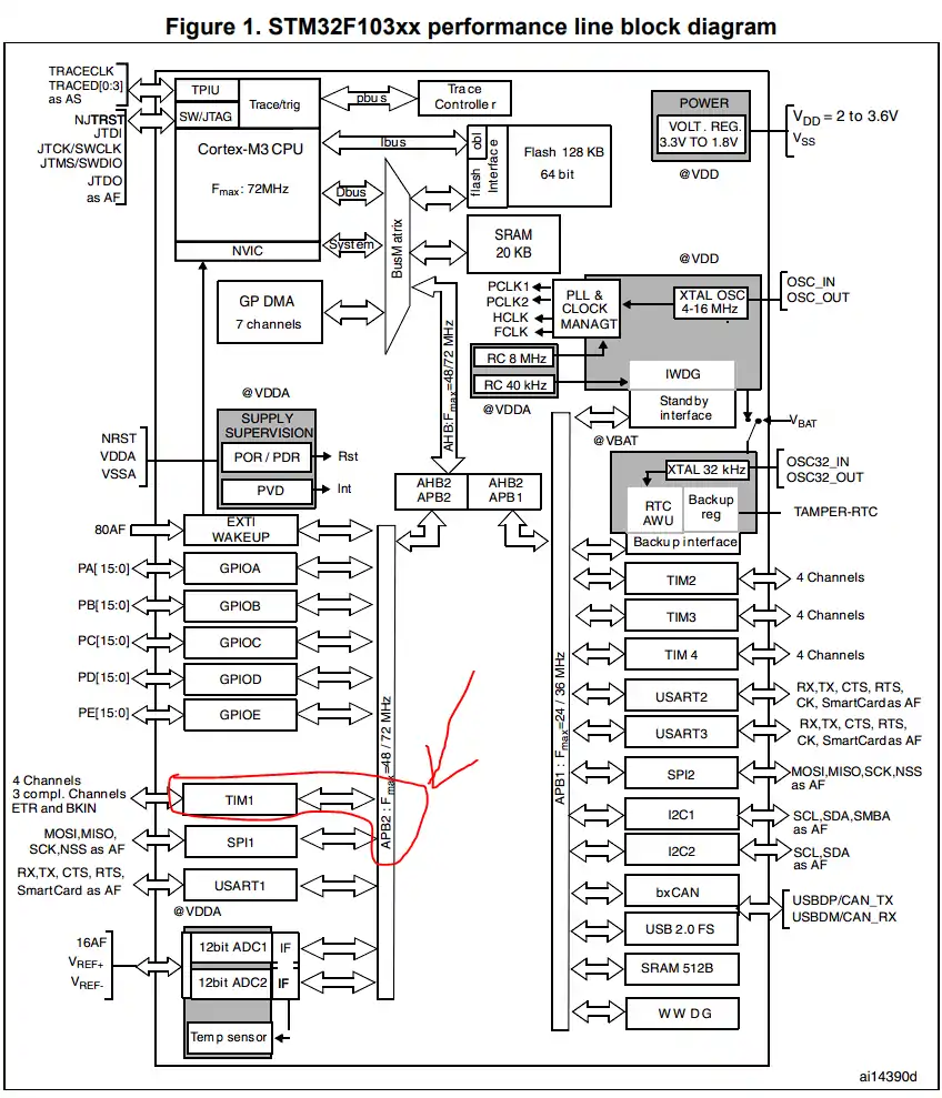
This is the most important part of this process, so read this section very carefully. First of all we need to decide which Timer to use for the process. There is no special requirement, just choose any one. I will use Timer1.
As you can see in the image below (from the datasheet of the MCU), the TIM1 is connected to the APB2 clock. This is a very important piece of information, and you should know it about the timer that you are going to use.
STM32 Clock Configuration
We will start with configuring the clock for the project. The image below shows the Clock setup for STM32F103C8 Microcontroller.
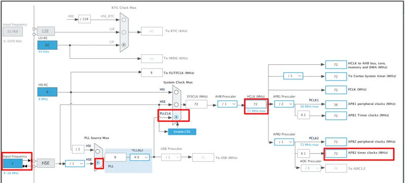
The Bluepill board (STM32F103C8) has a 8MHz oscillator on it. We will use this HSE crystal to run the system at maximum possible 72MHz clock.
Note that he APB2 Timer clock is also at 72MHz. The Timer1 is connected to APB2 bus, hence the Timer1 clock is also at 72MHz.
STM32 Timer Configuration for Microsecond Delay
The image below shows the TIM1 configuration.
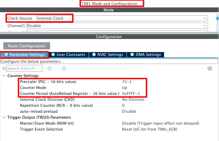
In this setup, we configure Timer 1 (TIM1) using the STM32CubeMX tool.
- Clock Source – Internal Clock: The timer uses the internal system clock as its source.
- Prescaler (PSC – 16 bits): We set the prescaler value to 71. Since the APB2 clock runs at 72 MHz, dividing it by 72 gives a timer clock of 1 MHz. This means the timer counts every 1 microsecond.
- Counter Mode: The counter increases upward, starting from 0 and going up to the AutoReload value.
- AutoReload Register (ARR – 16 bits): We set ARR to 0xFFFF (65535). This is the maximum value before the counter resets.
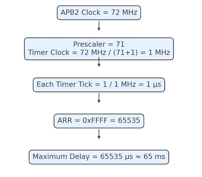
With this setup, the timer counts from 0 to 65535. Because the timer clock is 1 MHz, each count equals 1 µs. Setting a high ARR value allows us to create both short and long microsecond delays.
Finally, we enable PA1 pin as output. This helps us test the delay function by toggling the pin and checking the signal on an oscilloscope or Logic Analyzer.
STM32 HAL Timer Code for Microsecond Delay (delay_us Function)
Below is a simple, reliable way to implement a delay_us function using a HAL timer.
The Delay Function
Let’s write a function to block the CPU until the predefined count is reached.
void delay_us (uint16_t us)
{
	__HAL_TIM_SET_COUNTER(&htim1,0);  // set the counter value a 0
	while (__HAL_TIM_GET_COUNTER(&htim1) < us);  // wait for the counter to reach the us input in the parameter
}When the function is called with the parameter as the number of microseconds, the following operations takes place
- The TIM1 counter will reset to 0.
- The counter will start counting up, till the value (us) has been reached.
- Once the value is reached, the function will exit.
As I mentioned before, each count takes 1 us, and therefore the counter will keep counting in microseconds until the input value has reached. Once it happens, the control will come out of the loop, and we have had achieved the delay.
The Main Function
Inside the main function, we must start the timer after all the peripherals are initialized.
int main ()
{
  ....
  HAL_TIM_Base_Start(&htim1);  // start the Timer1
  while (1)
  {
    HAL_GPIO_TogglePin(GPIOA, GPIO_PIN_1);
    delay_us(10);
  }
}To use the required delay, all we have to do is call the function delay_us() we created above.
Result of STM32 Microsecond delay
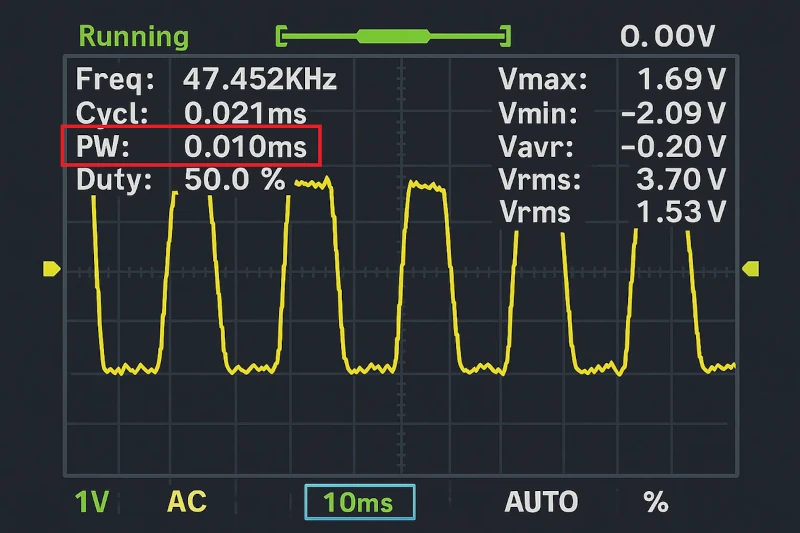
To test the delay_us function, I toggled the PA1 pin in a simple while loop. By observing the pin on an oscilloscope, we can verify whether the delay works correctly.
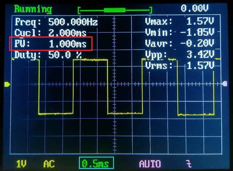
10us Delay
The image below shows the oscilloscope output when I used delay_us(10); inside the toggle loop. As you can see, the waveform confirms that the delay (PW) is around 10 microseconds (0.010ms), which matches our expectation.
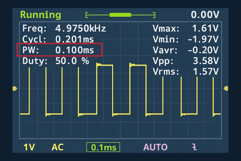
100us Delay
The following is the output when delay_us(100) is used to toggle the PA1 in a while loop.
1ms Delay
The image below shows the output when delay_us(1000) is used to toggle the PA1 in a while loop.
Video Tutorial
STM32 Microsecond Delay – Video Tutorial
This step-by-step guide explains how to create precise microsecond delays using STM32 timers. It covers the complete process including timer configuration, initialization code, and implementation of the delay function. To make it even easier to follow, I’ve also created a video walkthrough where I demonstrate the setup and show the delay function in real-time. Watch the video while following this tutorial to understand each step clearly and avoid common mistakes during timer configuration.
Watch the VideoConclusion
By using a hardware timer, you can easily generate an accurate 1 microsecond delay in STM32. Unlike HAL_Delay(), which only works in milliseconds, the delay_us() function built with HAL timer gives you precise control down to the microsecond. This approach works across most STM32 series, whether you use STM32CubeMX or direct HAL code.
With this method, you can reliably handle time-critical tasks such as ultrasonic sensors, RF modules, and fast communication protocols. If your STM32 project requires precise microsecond timing, the timer-based delay_us() function is the most efficient and dependable solution
Browse More STM32 Timer Tutorials
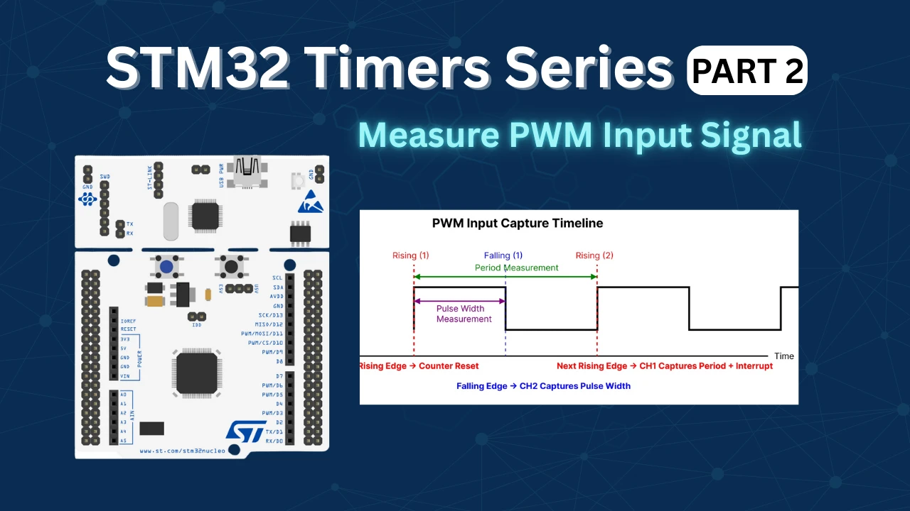
STM32 Timers (Part 2): How to Measure PWM Input Signal
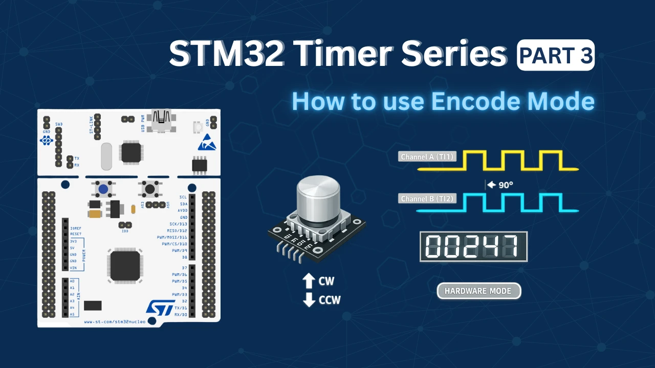
STM32 Timers (Part 3): How to use the Timer Encoder Mode
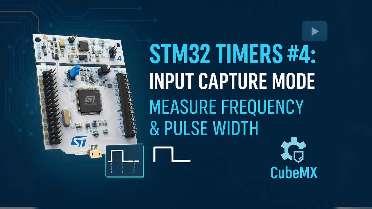
STM32 Input Capture: Measure Frequency & Pulse Width
STM32 Timer Synchronization: Slave Trigger Mode with CubeMX & HAL
STM32 Timers (Part 6): Timer Synchronization for 3-Phase PWM Generation
STM32 Timers (Part 7): Timer synchronization using Slave Reset mode
STM32 Timers (Part 8): How to Create a 48-Bit Counter by Cascading Timers
STM32 Microseconds Delay Project Download
STM32 Microseconds Delay FAQs


why the Duty cycle is 50% cant i change it?
This is not PWM tutorial. 50% is needed to create the equal ON and OFF timing.
Chumele
Thanks for your post. I am working on low power system. When I enter the sleep mode I must close the timer clock. But I need to micro second delay to normally working of system. How can I create microsecond delay without using timer . Have a nice day.
Nice Tutorial, thank you!
hi, Im getting 250khz with this code, what could be the problem? All settings are the same, Im using stm32l552CCT
It gives you delay…
Check what you are getting with HAL
hi, what you mean by that? code is exactly the same and 10us and 100us delays work but 1us takes double the time it should. so it is stuck in the function for too long?? I also tried dwt and the maximum speed I got with it was 360khz. Cpu is running at 100mhz. Also tried port manipulation directly but it didnt help because the cpu is stuck in the delay function.
New corrected code to work with latest HAL:
while ((uint16_t)__HAL_TIM_GET_COUNTER(&htim1) < us);
Hi! Thanks for this code! I’ve just discovered, what with later HAL it doesn’t work, because __HAL_TIM_GET… returns int32_t. To repair it code should be modified:
Thank you again!
Hi Admin
Thank you for the wonderful explanation. It works fine for me, however I would like to know about a few things, I think you can help me understand this in a better way.
However it would be better if you could throw some more light on points below :
1) The delay interval sometimes is 960ns (When delay(1); is passed in while(1)). Is this because of the clock tolerance or something else is causing this problem.
2) {while (__HAL_TIM_GET_COUNTER (&htim3)<delay);} -> How is this line creating the required delay?
3) What exactly does the value of htim.period = 0xffffe signify ?
Thanks in Advance
1) The clock will always have some minimum error, because it’s physically impossible build some oscillator without a jitter, the Microchip for example already build some timers with an jitter of 15 femtoseconds (but, as I said, the error still existing).
2) It’s created a required delay because the microcontroller will still in this empty while loop until the timer counting comes in the “delay” value, in other words: “until the whille setence becames false”
3) As these timers are 16-bit timers the period 0x0 – 0xFFFE means that you want to count using all capability of this timer, that is: counting starting at 0 and stop at 65.536-1(2^16 -1)
I would like to note that:
HAL_Delay(0); // causes a 1ms delay
Yeah it’s minimum 1ms..
what is the settings for creating milli seconds delay using this fucntion
Why is there only a “;” after the while statement (Delay_uS) and not a pair of curly brackets?
I think you can omit the curly brackets of there is no statement in the while loop.
My friend Frodinca says that while is a condition!!!!!! com’ on man think!
Hi I have done as per the above post and I am using STM32F103RB Nuleo board running at 72Mhz.
But could not toggle the GPIO. The program does not come out of the delay_us() function.
you have to start the timer in the main function.
Before while loop, use HAL_TIM_Base_Start (&htim1);
WHY 72MHZ IS REQUIRED ? BECAUSE EVEN IF WE TAKE 4MHZ OR 8MHZ AND DIVIDE IT BY 4 AND 8 RESPECTIVELY WE GET 1 MHZ FREQUENCY .
72mhz is by no means required, he is just using it as the stm he uses runs on 72 mhz default
you are the real genius!!!!
genius
Hi if I want to give decimal value like 20.2 in the actual parameter after changing from uint16_t to float of the delay function, how will the counter work
I don’t know. I haven’t tested that. But the counter can not count for the decimal half.
Why do you want to give decimal values anyway?
for example
for(int i = 0;i<10000;i++)
{
//make GPIO pin high
delay_us();
//make GPIO pin low
delay_us();
}
if I want to run this program for exactly 1.875 seconds then I have to do
1.875 / 10000 = 0.0001875
0.0001875*1000000(1Mhz) = 187.5(Microseconds)
there are 2 delays so 187.5/2 = 93.75 shoud be the parameter of the delay function, if I want to do this kind of claculation, what is the other option,
And also thanks for replying
Very unusual… I would suggest that you go for the nanoseconds than. 93.75 us means 93750 nanoseconds. You can setup the prescalar to give you a delay of 10nS in each count, and than count upto 9375
Nanosecond delay may work for me, thank you for your suggestion
Another approach would be to set up the prescalar such that each count corresponds to 93750 ns. Let’s assume that the APB is at 72 MHz. Now (93750×10^-9)x72MHz = 6750. This is your prescaler value. Setting this value would divide the timer clock to 10666.66666 Hz, which corresponds to 93.75 ms. Than u call delay (1). Because each count should take 93.75 ms
Hello! I left my comment on youtube video. But this theme is a little bit old, I do not know will You answer me here or on youtube.
Thank you very much. It works with stm32f4-discovery. But I have one problem with nucleo f767zi. It works when I programm by Keil and all the time after, until I power off and power on again. After that my code freezes when meet dwt_delay. I programm again – all works again. Do You have any ideas why? F767zi get clock not from ceramic crystal, it goes bypass clock source from st-link on board.
Hi,
This code doesn’t work on STM32L073RZ.
The DWT (Data Watchpoint and Tracing) is only available on Cortex M3/4/7.
So, if you want a delay of 1 us, you can use a Timer or the systick.
Thank you. I was getting crazy looking for dwt_stm32_delay.h file.
Anyone using dht22 on a stm32l07x chip?
Hai ,Can you help me to get HAL microsecond delay in STM32L073RZ board for one wire communication
The above code should work for STM32L073RZ. Just remember to do the following
NOTE:- Inside dwt_stm32_delay.h, change the #include”*.h” file according to your microcontroller.
Thanks for your code . it`s very good