Last Updated: March 23, 2026
Learn to control continuous‑rotation servo RPM via potentiometer (and optional button) on STM32: ADC setup, PWM mapping, direction & speed control. The project is available to download at the end of the post.
Recommended Resources:
This tutorial is a continuation of the previous one where we covered how to interface the continuous rotation servo motor with STM32. You must check it out first.
In this tutorial we will cover how to use the potentiometer and/or a button to control the RPM and direction of the motor. The potentiometer will be connected via the ADC, while the button will be used to generate an external interrupt. We will see both methods, one where we will control the RPM and direction with potentiometer alone, and another where we will use the potentiometer to vary the RPM while the button will be used to control the direction.
VIDEO TUTORIAL
You can check the video to see the complete explanation and working of this project.
Introducing Continuous-Rotation Servo Motor
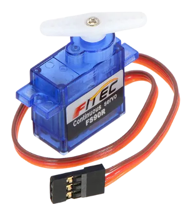
A continuous-rotation servo motor (also known as a 360-degree servo) is a type of servo that can rotate continuously in either direction, unlike standard servos which have limited angular movement. It is controlled using PWM signals, where the pulse width determines both the direction and speed of rotation. These motors are commonly used in robotics, mobile platforms, and automated systems where precise speed and direction control are needed rather than angle positioning.
Some of its important features are:
- Full 360° rotation with bidirectional control
- Speed and direction controlled via PWM signal
- Requires only one signal wire for control
- Ideal for wheeled robots, conveyor systems, and continuous motion tasks
All kind of servo motors have the following three wires:
- Black/Brown ground wire.
- Red power wire (around 5V).
- Yellow or White PWM wire.
WIRING DIAGRAM
Below is the image showing the connection between the STM32, motor, Potentiometer and the button.
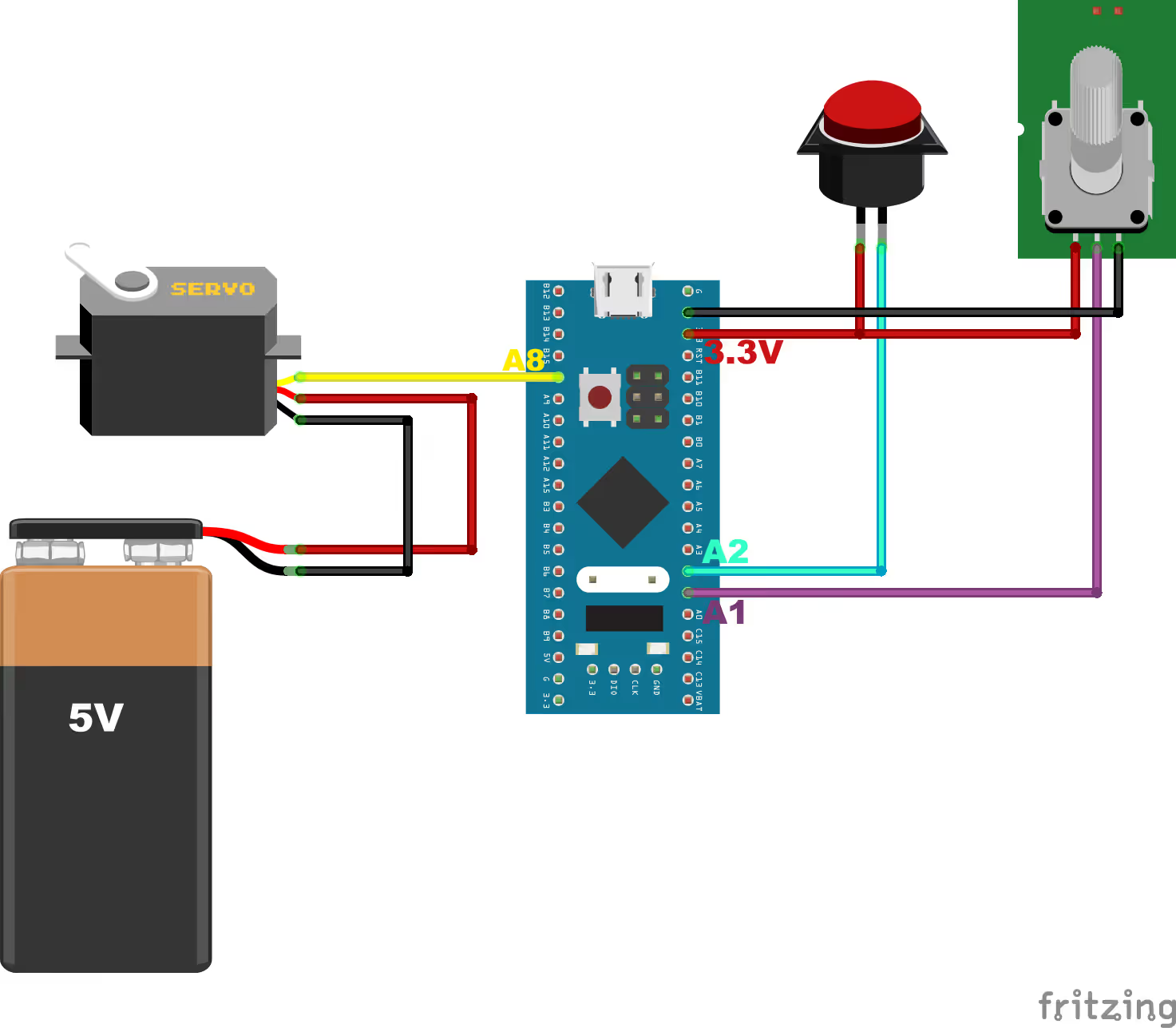
The Continuous servo motor is powered using a 5V battery.
- Yellow or White PWM wire from motor connects to the pin PA8 of the STM32. This is TIM1 CH1, which we have configured as the PWM out pin.
- Black/Brown ground wire from the motor connects with the Ground of the battery.
- Red power wire from motor connects to the VCC of the battery.
The potentiometer is connected with 3.3V from the MCU board. The middle pin (OUT) of the potentiometer is connected to pin PA1, which is ADC1 CHANNEL1.
The button is also connected with 3.3V of the MCU and the other pin is connected to the pin PA2, which we will use as the external interrupt pin.
CUBEMX CONFIGURATION
Clock Configuration
The clock configuration for the STM32F103C8T6 is shown below.
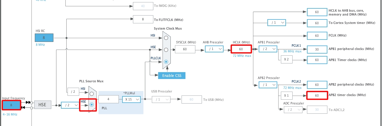
- External Crystal (8MHz) is used to provide the clock via the PLL.
- The system is running at 60MHz.
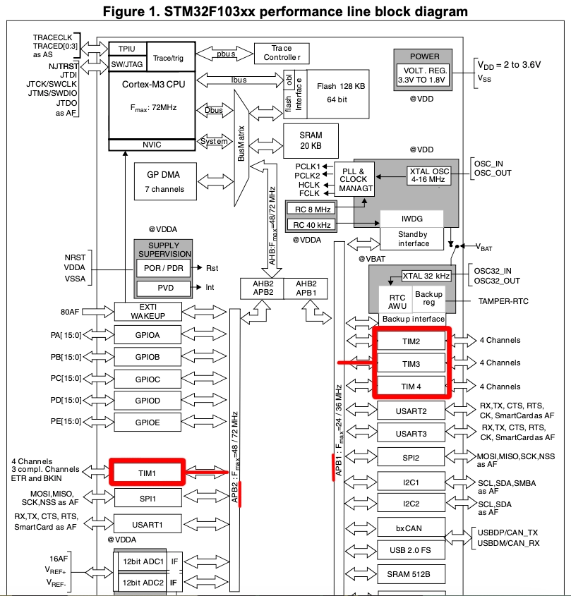
- I am going to use the TIM1 for the PWM, which is connected to the APB2 Bus (Check this Image).
- The APB2 Timer clock is at 60MHz right now.
PWM Configuration
The TIM1 configuration is shown below.
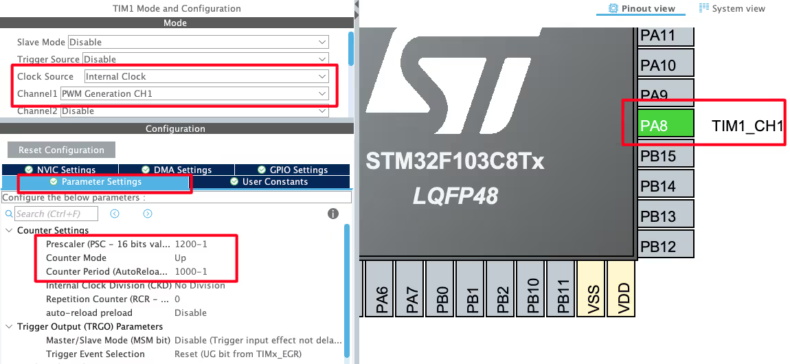
- Select the PWM channel for the Timer, I am using Channel 1.
- Set the Clock source as internal clock, which is at 60 MHz.
- Pin PA8 is set as the PWM output Pin and we will connect it to the Servo Motor Signal pin.
The output Frequency of the PWM signal depends on 3 parameters, Timer Clock, ARR and Prescaler.

Out of these parameters, the Timer Clock will remain constant at 60MHz throughout the project. We want to generate the PWM signal with the Frequency of 50Hz. To do so, I am setting the Prescaler and ARR values as shown below.

Here the Prescaler value is not as important but the ARR plays a very important role. We will see this in details below.
Note that the Pres and ARR input values must be 1 less than the actual values. This is because the library add a 1 to this value at the register level, so we must keep it 1.
ADC Configuration
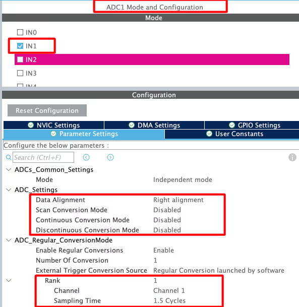
The Potentiometer is connected via the ADC1 channel1. I have kept the parameter settings to default, where we have 1 conversion with least sampling time of 1.5Cycles. Also the continuous conversion mode is disabled as we will manually call the conversion when we need the value.
Button Configuration
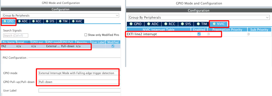
We have already seen in the connection diagram that the button is connected with 3.3V of the MCU. When the button is pressed, the pin PA2 will be pulled HIGH to this voltage. Therefore here in the configuration we will pull the pin PA2 to LOW by default. The trigger for the interrupt is set to falling edge (when the button is released).
Also make sure to enable the interrupt in the NVIC Tab.
Pinout

As shown in the image above,
- The pin PA1 is the ADC1 CH1. This is where the potentiometer is connected.
- The pin PA2 is the GPIO_EXTI2, the external interrupt pin. This is where the button is connected.
- The pin PA8 is TIM1 CH1 and this is where the motor is connected.
WITHOUT USING BUTTON
First we will see how to control the continuous servo using the potentiometer alone. Since we are not using the button here, the RPM and direction both will be controlled by the potentiometer itself.
We will read the ADC in the blocking mode. Below is the function for the same.
int readADC (void)
{
	HAL_ADC_Start(&hadc1);
	HAL_ADC_PollForConversion(&hadc1, 200);
	uint16_t ADC_VAL = HAL_ADC_GetValue(&hadc1);
	HAL_ADC_Stop(&hadc1);

	return (map(ADC_VAL, 0, 4095, 25, 125));  // without button
}- First start the ADC.
- Then Poll for the conversion to complete. I have used 200ms for the conversion.
- Then read the ADC value and store it in the variable ADC_VAL.
- Finally stop the ADC.
The STM32F103 has 12 bit ADC, so the values will range from 0 to 4095. If you remember from the previous tutorial, the pulse value for the servo motor ranges from 25 to 125. Therefore we need to convert the ADC values within this pulse range.
The map function does exactly this. It converts the ADC_VAL, which is ranging from 0 to 4095 to the range of 25 to 125.
Basically when the ADC value is 0, the output of the map function will be 25. When the ADC value is 2048, the output will be 75. And when the ADC value is 4095, the output will be 125.
Below is the source code for the map function.
long map(long x, long in_min, long in_max, long out_min, long out_max)
{
  return (x - in_min) * (out_max - out_min + 1) / (in_max - in_min + 1) + out_min;
}Below is the implementation of the main function.
int pulse = 75;
int main()
{
   .....
   HAL_TIM_PWM_Start(&htim1, TIM_CHANNEL_1);
   while (1)
   {
      pulse = readADC();
      __HAL_TIM_SET_COMPARE(&htim1, TIM_CHANNEL_1, pulse);
   }
}We will first define a pulse variable with the initial value of 75. This is the value where the pulse width is 1.5ms and the motor does not rotate at all.
Inside the main function we will start the TIM1 CHANNEL1 in the PWM mode.
Inside the while loop, we will read the ADC values. The function will output the mapped values, which will be stored in the pulse variable. These values will then be passed to the compare register.
You can check the output of the above code in the video shown below.
As you can see in the video above,
- When the slider is in the middle, the motor does not rotate. The ADC value is near 2048 and the pulse value is at 75 here.
- When the slider is moved near us, the ADC value increases towards 4095. The pulse value also increases from 75 towards 125. The motor start rotating in the counterclockwise direction.
- At the extreme end, the ADC value is near 4095 and the pulse value is at 125. The motor rotates at maximum RPM in the counterclockwise direction.
- When the slider is moved far from us, the ADC value decreases towards 2048. The pulse value also decreases from 125 towards 75. The motor start slowing down in the counterclockwise direction.
- When the slider is in the middle, the ADC value is near 2048 and the pulse value is at 75. The motor stops completely at this point.
- When the slider move further away from us, the ADC value decreases towards 0. The pulse value also decreases from 75 towards 25. The motor start rotating in the clockwise direction.
- At the extreme end, the ADC value is near 0 and the pulse value is at 25. The motor rotates at maximum RPM in the clockwise direction.
The motor can be controlled by the potentiometer alone, but we have to split it into 2 halves. One half control the movement in the clockwise direction while the other controls it in the counterclockwise direction.
WITH BUTTON
Let’s assume that we want to control the RPM of the motor for the entire length of the potentiometer. In such case we can utilise the rotation in only one direction. To switch between the directions, we can add a button to the project. I have already explained the connection above, so here we will just look into the code.
const int pulse_fix = 75;
int pulse  = 0;
int button = 0;The variable pulse_fix is a constant which contain the value 75. This is the value where the pulse width is 1.5ms and the motor does not rotate at all. The pulse variable will store the pulse value which we will pass to the compare register. The button variable will keep track of how many times the button has been pressed.
int readADC (void)
{
	HAL_ADC_Start(&hadc1);
	HAL_ADC_PollForConversion(&hadc1, 200);
	uint16_t ADC_VAL = HAL_ADC_GetValue(&hadc1);
	HAL_ADC_Stop(&hadc1);

//	return (map(ADC_VAL, 0, 4095, 25, 125));  // without button
	return (map(ADC_VAL, 0, 4095, 0, 50));  // with button
}The readADC function is modified a little. Here we will output the values from 0 to 50.
Basically when the ADC value is 0, the output of the map function will be 0. And when the ADC value is 4095, the output will be 50.
Remember that the pulse_fix constant is at 75. We will add or subtract the ADC mapped values from the pulse_fix variable. This will result in the values ranging from either 25 (75-50) to 75(75-0) or from 75 (75+0) to 125(75+50).
The button is connected to the pin PA2, which is pulled LOW by default. When the button is pressed, this pin will be pulled HIGH to 3.3V. This will trigger an external interrupt and the GPIO_EXTI_Callback is called.
void HAL_GPIO_EXTI_Callback(uint16_t GPIO_Pin)
{
	if (GPIO_Pin == GPIO_PIN_2)
	{
		button++;
		if (button > 2) button = 1;
	}
}Inside this callback,
- We will increment the button variable.
- If the button variable is greater than 2, reset it back to 1.
This will ensure that the value of the button variable will either be 1 or 2. We can use this value to switch between the direction of rotation of the motor.
int main()
{
   .....
   HAL_TIM_PWM_Start(&htim1, TIM_CHANNEL_1);
   while (1)
   {
      if (button == 1)
      {
	  pulse = pulse_fix + readADC();  // 75 - 125
      }

      else if (button == 2)
      {
	  pulse  = pulse_fix - readADC();  // 25 - 75
      }
      __HAL_TIM_SET_COMPARE(&htim1, TIM_CHANNEL_1, pulse);
   }
}Inside the main function we will start the TIM1 CHANNEL1 in the PWM mode.
Inside the while loop, we will check the current value of the button variable.
- If the button variable is 1, we will add the mapped ADC values with the fixed pulse value. This will result in the values ranging from 75 to 125 for the entire range of the potentiometer (0 to 4095). The motor will rotate only in the counterclockwise direction.
- If the button variable is 2, we will subtract the mapped ADC values from the fixed pulse value. This will result in the values ranging from 25 to 75 for the entire range of the potentiometer (0 to 4095). The motor will rotate only in the clockwise direction.
This way we can control the RPM of the motor for the entire length of the potentiometer and the direction of rotation will be separately controlled by the button.
