Home ▸ STM32 Tutorials ▸
Updated On: June 20, 2026
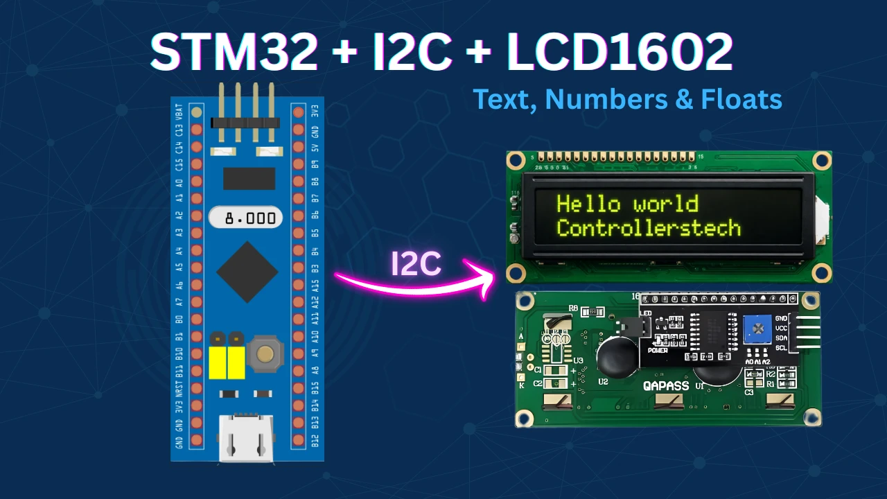
Interface I2C LCD1602 (PCF8574) with STM32 HAL & CubeIDE
Wiring a 16×2 LCD to STM32 with 6+ GPIO pins is messy. The PCF8574 I2C expander cuts that down to just two pins — SDA and SCL — while the HAL library handles all the low-level I2C transactions.
This tutorial shows you how to interface an I2C LCD1602 with an STM32F103 using the PCF8574 expander, STM32CubeMX, and CubeIDE with HAL. You’ll configure I2C in CubeMX, understand the PCF8574 address and pin mapping, and write HAL code to display strings, integers, and floats on the LCD. The complete CubeIDE project is available to download below.
If you’re working with other displays, also check out the STM32 LCD tutorials collection and the STM32 OLED tutorials for SPI/I2C OLED options.
You can also check out other Displays interfaced with STM32 Microcontrollers:
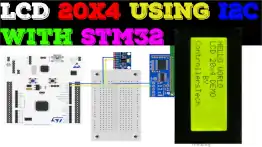
- Interface LCD 20×4 with STM32 using the I2C
- Interface LCD1602 display with built‑in I²C driver AIP31068
- Interface SSD1306 OLED Display with STM32 (via I²C)
- Interface SH1106 1.3″ OLED with STM32 via I²C
- Interface LCD 16×2 with STM32 without I²C
- Interface 2.8″ ILI9341 Display with STM32 using SPI
How I2C LCD1602 Works with PCF8574
The PCF8574 is an 8-bit I/O expander that bridges your STM32’s I2C bus to the parallel interface of a 16×2 LCD. Because it uses only SDA and SCL, you save six or more GPIO pins compared to a direct parallel connection.
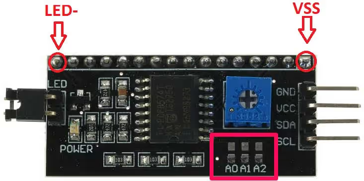
PCF8574 I2C Address — Default & How to Change It
Every device on the I2C bus needs a unique 7-bit address. The PCF8574’s address uses the fixed upper nibble 0100, while the lower three bits are set by hardware pins A2, A1, A0 on the module.
Default address (A0, A1, A2 all HIGH): Binary: 0100 1110 → Hex: 0x4E
To change the address, pull any of A0–A2 to GND:
| A2 | A1 | A0 | 7-bit Address |
|---|---|---|---|
| H | H | H | 0x4E (default) |
| H | H | L | 0x4C |
| H | L | H | 0x4A |
| … | … | … | … |
This allows up to 8 PCF8574 devices on one I2C bus. Note: the R/W bit is the 8th bit of the transmitted byte, not part of the address itself.
PCF8574 Pin Mapping to LCD1602
The PCF8574 exposes pins P0–P7, which map to the LCD1602 control and data lines:
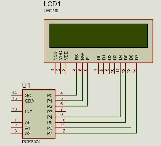
| PCF8574 Pin | LCD1602 Function |
|---|---|
| P0 | RS — 0 = command, 1 = data |
| P1 | R/W — always LOW (write-only) |
| P2 | EN — Enable strobe |
| P3 | Backlight — HIGH = ON |
| P4–P7 | D4–D7 (4-bit data bus) |
Because only four data lines are available, the library always operates in 4-bit mode and transmits each byte as two back-to-back nibbles.
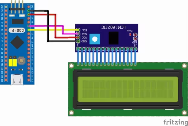
Wiring STM32 to I2C LCD (PCF8574)
Schematic & Connection Table
The PCF8574 module mounts directly onto the back of the LCD1602 header. Connect the module to your STM32F103 as follows:
| PCF8574 Pin | STM32F103 Pin | Function |
|---|---|---|
| VCC | 5 V | Power supply |
| GND | GND | Ground |
| SDA | PB7 | I²C data |
| SCL | PB6 | I²C clock |
Note:
The LCD1602 runs on 5 V logic. Most PCF8574 modules include onboard pull-up resistors on SDA and SCL, so no external pull-ups are required. Confirm on your specific module’s datasheet.
CubeMX Setup, HAL Code & Results
STM32 Clock Configuration
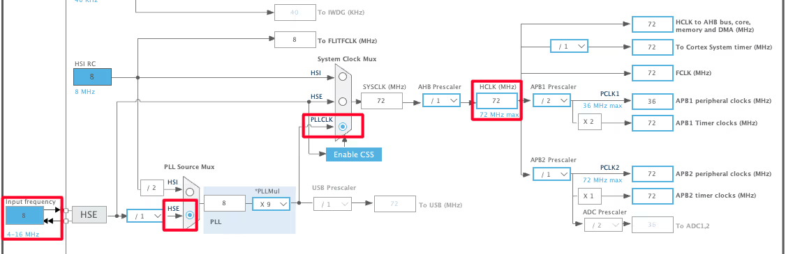
The STM32F103 is clocked from an 8 MHz external crystal. Enable the PLL multiplier to reach the maximum 72 MHz system clock. I2C timing is derived from the APB1 bus, so verify APB1 does not exceed 36 MHz.
I2C1 Configuration
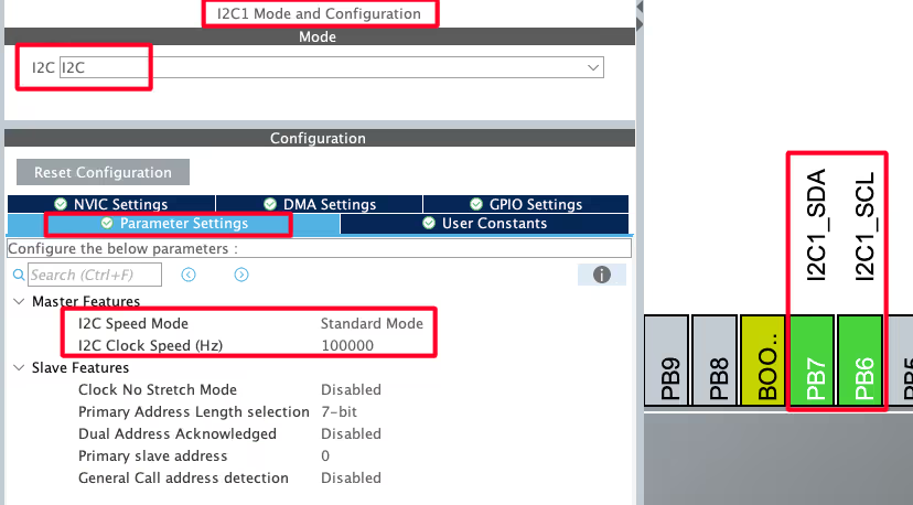
Enable I2C1 in CubeMX and set:
- Mode: I2C
- Speed: Standard Mode, 100 kHz
- Pins: PB6 (SCL), PB7 (SDA) (auto-assigned)
Generate the code. CubeMX will create hi2c1 and the MX_I2C1_Init() function in main.c.
lcd_send_cmd() — Sending Commands
The LCD is operated in 4-bit mode, so every command byte is split into two nibbles and transmitted as four bytes over I2C (upper nibble EN-high, upper nibble EN-low, lower nibble EN-high, lower nibble EN-low).
void lcd_send_cmd(char cmd)
{
    char data_u = (cmd & 0xF0);           // upper nibble
    char data_l = ((cmd << 4) & 0xF0);   // lower nibble

    uint8_t data_t[4];
    data_t[0] = data_u | 0x0C;   // EN=1, RS=0
    data_t[1] = data_u | 0x08;   // EN=0, RS=0
    data_t[2] = data_l | 0x0C;   // EN=1, RS=0
    data_t[3] = data_l | 0x08;   // EN=0, RS=0

    HAL_I2C_Master_Transmit(&hi2c1, SLAVE_ADDRESS_LCD,
                             (uint8_t *)data_t, 4, 100);
}The mask 0x0C sets EN (P2) and Backlight (P3) HIGH while keeping RS (P0) LOW, signalling a command transaction. EN is then pulled LOW in the next byte to clock the data into the LCD.
lcd_send_data() — Sending Data
Identical nibble-split approach, but RS (P0) is set HIGH (0x0D / 0x09) to tell the LCD the byte is character data, not a command.
void lcd_send_data(char data)
{
    char data_u = (data & 0xF0);
    char data_l = ((data << 4) & 0xF0);
    uint8_t data_t[4];
    data_t[0] = data_u | 0x0D;   // EN=1, RS=1
    data_t[1] = data_u | 0x09;   // EN=0, RS=1
    data_t[2] = data_l | 0x0D;   // EN=1, RS=1
    data_t[3] = data_l | 0x09;   // EN=0, RS=1
    HAL_I2C_Master_Transmit(&hi2c1, SLAVE_ADDRESS_LCD,
                             (uint8_t *)data_t, 4, 100);
}lcd_init() — Initialization Sequence
The initialization sequence follows the LCD1602 datasheet’s 4-bit startup procedure exactly:
void lcd_init(void)
{
    HAL_Delay(50);          // >40 ms power-on delay
    lcd_send_cmd(0x30);
    HAL_Delay(5);           // >4.1 ms
    lcd_send_cmd(0x30);
    HAL_Delay(1);           // >100 µs
    lcd_send_cmd(0x30);
    HAL_Delay(10);
    lcd_send_cmd(0x20);     // switch to 4-bit mode

    lcd_send_cmd(0x28);     // 4-bit, 2-line, 5×8 font
    HAL_Delay(1);
    lcd_send_cmd(0x08);     // display OFF
    HAL_Delay(1);
    lcd_send_cmd(0x01);     // clear display
    HAL_Delay(2);
    lcd_send_cmd(0x06);     // entry mode: cursor increment, no shift
    HAL_Delay(1);
    lcd_send_cmd(0x0C);     // display ON, cursor OFF, blink OFF
}lcd_send_string() — Printing Strings
void lcd_send_string(char *str)
{
    while (*str) lcd_send_data(*str++);
}Iterates over each character until the null terminator, calling lcd_send_data() for each byte.
lcd_put_cur() — Setting Cursor Position
void lcd_put_cur(int row, int col)
{
    switch (row)
    {
        case 0: col |= 0x80; break;  // DDRAM row 0 starts at 0x00
        case 1: col |= 0xC0; break;  // DDRAM row 1 starts at 0x40
    }
    lcd_send_cmd(col);
}Row 0, column 0 → command 0x80. Row 1, column 3 → command 0xC3.
main() — Print Strings, Numbers & Floats
Print a String
lcd_init();
lcd_put_cur(0, 0);
lcd_send_string("HELLO WORLD");
lcd_put_cur(1, 0);
lcd_send_string("from CTECH");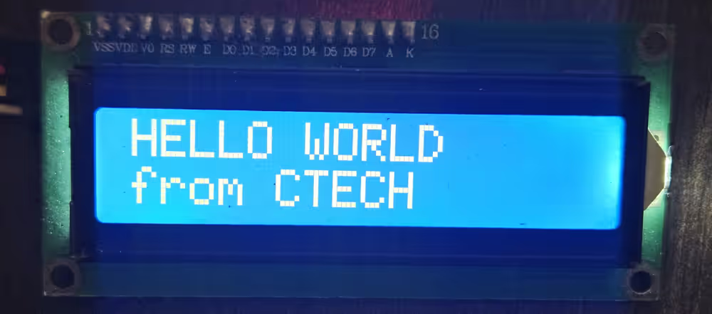
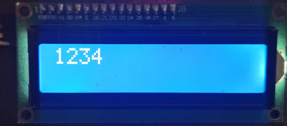
Print an Integer
The LCD only accepts ASCII, so use sprintf to convert before sending:
lcd_init();
int num = 1234;
char numChar[5];
sprintf(numChar, "%d", num);
lcd_put_cur(0, 0);
lcd_send_string(numChar);Buffer size = number of digits + 1 for the null terminator. Use %d for signed integers.
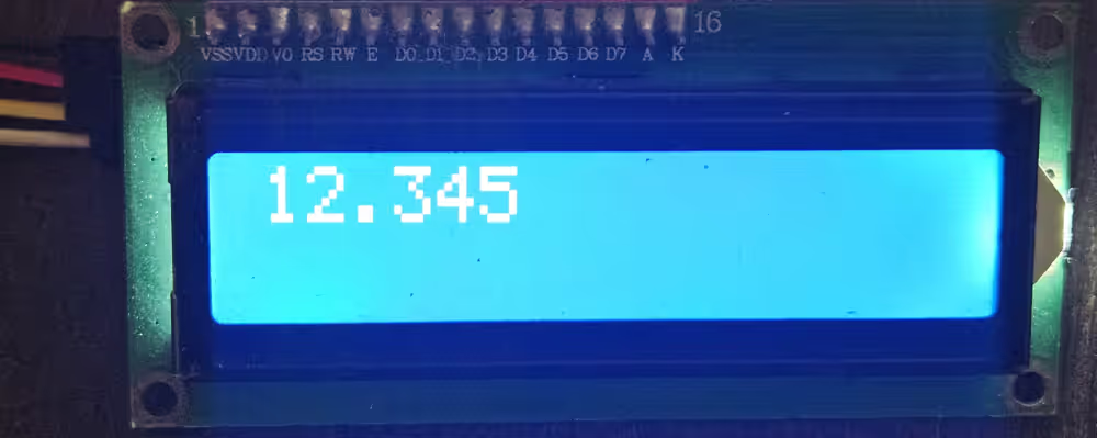
Print a Float
lcd_init();
float flt = 12.345;
char fltChar[7];
sprintf(fltChar, "%.3f", flt);
lcd_put_cur(0, 0);
lcd_send_string(fltChar);%.3f formats to three decimal places. Buffer size accounts for sign, digits, decimal point, decimals, and null terminator.
STM32 I2C LCD1602 (PCF8574) — Video Tutorial
Watch the full walkthrough: PCF8574 address configuration, STM32CubeMX I2C setup, wiring, and HAL code to print strings, integers, and floats on a 16×2 LCD1602 using STM32F103.
STM32 I2C LCD1602 (PCF8574): FAQs
Conclusion
Interfacing a 16×2 LCD over I2C using the PCF8574 is one of the most GPIO-efficient display setups you can build on an STM32. Two pins, a small HAL library, and a straightforward CubeMX configuration are all you need to print strings, integers, and floats on screen.
The same lcd_send_cmd() / lcd_send_data() pattern scales cleanly — swap in a different I2C peripheral, adjust SLAVE_ADDRESS_LCD, and the library works as-is. For projects where you need a larger panel, the same technique applies to the 20×4 I2C LCD on STM32. If GPIO count isn’t a constraint, the parallel LCD1602 tutorial covers the direct 8-bit and 4-bit wiring approach.
Download the complete CubeIDE project below, including the i2c-lcd.c/.h library and the main.c examples for strings, integers, and floats.
Download STM32 I2C LCD1602 Project Files (STM32F103)
Complete CubeIDE project including i2c-lcd.c / i2c-lcd.h library and main.c examples for strings, integers, and floats. Free to download — support the work if it helped you.
Browse More STM32 Display Tutorials
GLCD 128×64 ST7920 interfacing with STM32

Interface 16×2 LCD with STM32 (No I2C) — 4-bit Guide

Custom characters in LCD 1602 || STM32
Interface I2C-LCD1602 (AIP31068) with STM32


void lcd_init(void) {
HAL_Delay(50); // Wait for >40ms after power on
lcd_send_cmd(0x30);
HAL_Delay(5); // Wait for >4.1ms
lcd_send_cmd(0x30);
HAL_Delay(5); // Wait for >100us
lcd_send_cmd(0x30);
HAL_Delay(150);
lcd_send_cmd(0x02); // Set to 4-bit mode
// HAL_Delay(10);
lcd_send_cmd(LCD_FUNCTIONSET | LCD_4BITMODE | LCD_2LINE | LCD_5x8DOTS); // Function set: 4-bit mode, 2 lines, 5×8 dots
// HAL_Delay(1);
lcd_send_cmd(LCD_DISPLAYCONTROL | LCD_DISPLAYON | LCD_CURSOROFF | LCD_BLINKOFF); // Display off
lcd_send_cmd(LCD_ENTRYMODESET | LCD_ENTRYLEFT | LCD_ENTRYSHIFTDECREMENT);
// HAL_Delay(1);
lcd_clear(); // Clear display
// HAL_Delay(1);
// lcd_send_cmd(0x06); // Entry mode set: increment cursor, no display shift
// // HAL_Delay(1);
// lcd_send_cmd(0x0C); // Display on, cursor off, no blink
}
this right intialize
Hi, i am trying out the code on another controller, the i2c waveforms are correct but still sometimes lcd does not print anything. In cases where it works, there is no difference in waveforms. What may be the issue. The POT is adjusted correctly.
doesn’t write anything in the second line… (
doesn’t write anything in the second line… (
i add “i2c-lcd.h” and “i2c-lcd.c” into my project,1602 LCD can not print number(0,1,2) with ” lcd_send_data(1)”.howeverm LCD can print “string”.
displays can only print ascii characters.
You need to convert numbers into the relevant ascii character.
sprintf (buffer, “%d”, num);
lcd_send_string (buffer);
void lcd_clear (void)
{
lcd_send_cmd(0x01);
delay_ms(2);
}
//Add function
void lcd_gotoxy(unsigned char x, unsigned char y){
unsigned char xy;
if(y==0){xy=0x80;}
if(y==1){xy=0xC0;}
if(y==2){xy=0x94;}
if(y==3){xy=0xD4;}
xy=xy+x;
lcd_send_cmd (xy);
}
Hi, I want to suggest the following code for PC8574 with 9 pins (blue board)
//Rs–>P0, RW–>P1, E–>P2, D4–>P4, D5–>P5, D6–>P6, D7–>P7
void lcd_send_cmd(char cmd)
{
uint8_t cmd_t[4];
cmd_t[0]=(cmd&0xf0)|(0x04); //cmd_u ,E=1, RS=0
cmd_t[1]=(cmd&0xf0); //E=0, RS=0
cmd_t[2]=((cmd<<4)&0xf0)|(0x04); //cmd_l E=1, RS=0
cmd_t[3]=((cmd<<4)&0xf0); //E=0, RS=0
HAL_I2C_Master_Transmit(&hi2c1, SLAVE_ADDRESS_LCD, (uint8_t *) cmd_t, 4, 200);
}
void lcd_send_data(char data)
{
uint8_t data_t[4];
data_t[0]=(data&0xf0)|(0x05); //data_u , E=1, RS=1
data_t[1]=(data&0xf0)|(0x01); //E=0, RS=1
data_t[2]=((data<<4)&0xf0)|(0x05); //data_l, E=1, RS=1
data_t[3]=((data<<4)&0xf0)|(0x01); //E=0, RS=1
HAL_I2C_Master_Transmit(&hi2c1, SLAVE_ADDRESS_LCD, (uint8_t *) data_t, 4, 200);
}
thank you so much!!
hi, i follow every steps but on my lcd i see only the ligth but no word. Can you help me plese?
try to adjust the potentiometer on your lcd i2c adapter-board. This solved that problem for me
it’s work very fine. Can you help me to print the value of the potentiometer linked on ADC please?
Hi I imported the project but it will not run it keeps saying “this launch configuration requires the selected build configuration to use the MCU ARM GCC toolchain”
how do I fix this?
Hi everyone. I have a problem when my program does software reset, my LCD shows noisy characters after running LCD_init(). I have to reset it again to work properly. How can I fix it? It’s imprortant when I use IWDG
When I try to display numbers above 9, it prints it corresponding ASCII characters.How will I print a value stored in a variable which is incremented or varying.
Thanks for the tutorial.It works fine
I also wanted to print ADC values which have float and integer values.
you should use sprintf to convert the numbers to characters.
Do you have an example code for that function with the above-attached header files and source files ? Please send it or mention it if you have.
let’s say you want to convert 1234 to characters.
unsigned int num = 1234;
char buffer[4];
sprintf (buffer, “%u”, num);
does it work in mode 8bit?
You need to modify the init code as per the 8 bit initialization
also the lcd_send_cmd and data functions. There we split the data into upper and lower half, so just don’t split it and it will work
Hi, as D0 – D3 are not connected – IMHO also 8-bit mode can not work. True?
yes not with this setup. But the same code with little modification can work..
hi
I did not understand how to change the code for 8bit.
please give an example
what you mean 8 bit ?
8 bit initialization.
Can you send modified code for the “lcd_send_cmd” function?
i modify “lcd_init” function from data sheet but I could not modify the code of
“lcd_send_cmd” and “lcd_send_data”
you mean this ? https://controllerstech.com/interface-lcd-16×2-with-stm32-without-i2c/
no,this code for 8 bit mode
why 8 bit mode ? The PCF only connects to 4 data pins of the LCD. The 8 bit code won’t work
its works, but i am having problems with the brightness and it is not the potentiometer, where should i change it?
I think you should use external power source
sir i want to toggle curser set position on lcd
You are telling so many topics, you are wasting your time. We are watching you until the end, but you do not share any files. How are we going to experiment ourselves? Every download link contains ads. it still does not download. Why follow as long as you don’t provide any support here?
There are not even header and source files suitable for your program. Or you don’t even have a general program. If we get it wrong, at least somewhere, we can download your program and try it out.
But there is no file.
Sorry man. I found it . Please change the still for download button:))
I am so sorry . My fault. I did not see it.
where can download the files? I can`t see the link
now check. I am making some changes in the website… so it might have got deleted… FIXED NOW
https://controllerstech.com/wp-content/uploads/2019/12/TUT_LCD_I2C_F103_CUBEIDE.zip
ok
How can set cursor in another position?
Another way to clear the screen is:
lcd_send_cmd(1);
Cheers
wow thank you so much it work better than lcd_clear() in the library
Excellent. Worked first time. Thanks a lot.
well done, thanks
I had to use Direct manipulation on the I2C registers on my Nucleo STM32F767 to make this thing works -_-
There are slightly different I2C parts with different I2C address 0x3F for -AT and 0x27 for -T
Refer to spec and modify you code for part you have.
The PCF8574AT has I2C address as shown in this code starting with 0x3F.
The PCF8574T has different I2C address starting with 0x27.
Refer to part spec.
You may need to modify I2C address for the part you have.
hi
how can send custom character with your library?
(is it even possible)
hi again
i managed to create custom character using your library like below:
/* code
const char UserFont[8][8] =
{
{ 0x11,0x0A,0x04,0x1B,0x11,0x11,0x11,0x0E },
{ 0x10,0x10,0x10,0x10,0x10,0x10,0x10,0x10 },
{ 0x18,0x18,0x18,0x18,0x18,0x18,0x18,0x18 },
{ 0x1C,0x1C,0x1C,0x1C,0x1C,0x1C,0x1C,0x1C },
{ 0x1E,0x1E,0x1E,0x1E,0x1E,0x1E,0x1E,0x1E },
{ 0x1F,0x1F,0x1F,0x1F,0x1F,0x1F,0x1F,0x1F },
{ 0x0E,0x1F,0x11,0x11,0x13,0x17,0x1F,0x1F },
{ 0x1F,0x11,0x11,0x11,0x11,0x11,0x11,0x1F }
};
lcd_send_cmd(0x40); // Set CGRAM address counter to 0
char const *p1;
p1 = &UserFont[0][0];
for (int i = 0; i < sizeof(UserFont); i++, p1++){
lcd_send_data(*p1);
}
lcd_send_cmd(0x80);
*/
now sending character 0x00 to 0x07 displays 8 predefined custom character
Ok I will test it and include it in the code.. Do you want the reference ?
If there is anyone that can help me i send him my code. The circuit that i mounted is the same of the youtube tutorial.
Hello, i have problem with this project. Can anyone help me? I found the i2c addres with i2c scanner did with keil, not arduino: it’s 0x3F. The code is the same that i have downloaded from this site; maybe change some setting into frequency or clock because i use an stm32f767zi. Please help me.
Hi, is it possible to avoid using HAL_DELAY() in void lcd_init (void)? What else can I use in the init function instead of HAL_DEALY() ?
yeah It’s possible.. You can use that microsecond delay instead.. Or just use some empty loop
Error building…
../Core/Src/i2c-lcd.c:20: undefined reference to `hi2c1′
did you select I2C while setting up cubemx ?
Hi Everyone, I am using with stm32f072 board and have an lcd with PCF8574 converter. The project is building successfully but for some reason I do not get anything on my lcd. What could be the reason? This is the first time I am trying to send something to my lcd.
Try adjusting the potentiometer for the contrast
I have done that. I am not sure the slave address though. How can I make sure 0x4E is an appropriate one?
if you are using pcf8574 (not any other version of it) than the address is 0x4E. Read the datasheet for the address related querry
That is interesting but I have different manual – by Philips Semiconductors. I do not have that address reference in there, but for addressing I have a slave address: S 0 1 0 0 A2 A1 A0 0 A
that is how the addressing is. 0100 (4) and A2 A1 A0 pins are high by default. which makes the default address as 0x4E.
Ok, I do not know how it came but it is working now 🙂 Thank you.
Do I need to change / modify libs for sending ADC temperature results to my lcd ?
Hi, I am struggling to get it working. For some reason, am not successful. Can you share your code ([email protected]) and wiring of the setup? It will be a great help.
For binary 01001100 , I think it should be 76 (decimal) and it means 0x4C instead of 0x4B
Yeah you are right… My bad, I’ll fix it.
Hello!
Redid the project in STM32CUBEIDE does not work. Blue pill board.
It should work. I’ll check and upload the CUBEIDE working code..
How can I send a project?
Download the project now. It works alright with CUBEIDE
I don’t understand why the code does not work. I have the address I2C = 3F.PB8-SCL, PB9-SDA.
I collected the project with this data, there are no errors. The code does not work. Other code in this configuration works. What is wrong?
If you are using PCF8574, the address is 0x4E.
I am using PCF8574AT. The I2C address scanner on the terminal shows address = 3F.
Stm32 uses the i2c protocol in a manner that the address would be (address+read/write). This way in order to write (0), the address would be 0x7E for you.
Everything began to work. In the i2c-lcd.c file I replaced #define SLAVE_ADDRESS_LCD 0x4E //., #Define SLAVE_ADDRESS_LCD 0x3F << 1 //. Thank you very much for your work.
Are you planning to make an LCD 1602 project without an I2C interface in CUBEIDE?
Sure, could do that. Nobody ever requested it so i never bothered 😁. I will do that soon.
This is very good. I will look forward to it.
Hello, Thank you for this code.I use your code, when I initialize LCD my LCD’s back-light is goes off,why this happens?could you help me?
The backlight was the issue but it’s fixed now. I don’t know what is happening in your case. Check the send command function in i2clcd.c file and confirm if it is same as below
0x0c , 0x08, 0x0c, 0x08
And data function should be 0x0d, 0x09, 0x0d, 0x09.
I’m using your code but all the i2c bus is sending are ‘Setup Write to [&] + NAK’ packets over and over and over again. I’m using salae’s logic program and an analyzer to get the data. The board is a blue pill with some chinese knockoff STM32f103c8 but it’s working as normal so far except for the code. Any ideas??
What are u using to connect lcd to the I2C ?
If it is pcf8574, are u using the address 0x4E ?
It’s an I2C backpack module for the 16×2 lcd screen. The chip is a PFC8574AT and using the arduino and some handy I2C scanner code I found that the address is 0x27 which I also placed in the code instead of your provided address.
The address for the PCF8574 is not 0x27. Don’t use the arduino one. Look at the datasheet and use the proper address. I think it’s 0x4E
It works now, my chip is PCF8574AT, the address is 7E, thanks,
I changed on backlight side, replace the transistor with 470 ohm resistor, so it’s on always…cheers…
it’s not working yet with STM32F107VCT6, will it work with 3.3V supply and bus ? thanks
What error are u facing ? Are you using pcf8574 ? Is the slave address correct ? Do the debugging and find out the error type. Only than i can help you.
And keep the vcc at 5v for the lcd
Sck and sda are connected to the microcontroller pins so they will be at 3.3v always.
Also try using pull up at sck and sda and see if it helps.
i’m having problems using it, i did an exact copy of the code, activated the I2C on cubemx and the display isn’t doing anything at all besides turning on and i already adjusted brightness, i tried to measure RW pin with multimeter and i got a 5V signal everytime i did it, so i think it’s the RW but i don’t know how i change it
Can you share your entire code with cubemx file to [email protected]
can i send my code and check it please?
best regards sir
Try downloading the code again. It’s updated just now. If it doesn’t work than contact me at [email protected]
it doesn’t work in my 16×4 lcd, can you help me to use 16×4 lcd?
Hello, can I use your i2c-lcd library for STM32F072B-discovery? Is it ok when I replace in i2c-lcd.h #include “stm32f4xx_hal.h” for #include “stm32f0xx_hal.h”. Thank you.
yeah sure you can use it
I don’t know where i do mistake. The address of display I have default 0x4E.
/* Includes ——————————————————————*/
#include “main.h”
#include “i2c-lcd.h”
/* Private variables ———————————————————*/
I2C_HandleTypeDef hi2c1;
/* Private function prototypes ———————————————–*/
void SystemClock_Config(void);
static void MX_GPIO_Init(void);
static void MX_I2C1_Init(void);
/* Private user code ———————————————————*/
int main(void)
{
/* Reset of all peripherals, Initializes the Flash interface and the Systick. */
HAL_Init();
/* Configure the system clock */
SystemClock_Config();
/* Initialize all configured peripherals */
MX_GPIO_Init();
MX_I2C1_Init();
/* Infinite loop */
while (1)
{
lcd_init ();
lcd_send_string (“HELLO WORLD”);
HAL_Delay(100);
}
}
/**
* @brief System Clock Configuration
* @retval None
*/
void SystemClock_Config(void)
{
RCC_OscInitTypeDef RCC_OscInitStruct = {0};
RCC_ClkInitTypeDef RCC_ClkInitStruct = {0};
RCC_PeriphCLKInitTypeDef PeriphClkInit = {0};
/** Initializes the CPU, AHB and APB busses clocks
*/
RCC_OscInitStruct.OscillatorType = RCC_OSCILLATORTYPE_HSI;
RCC_OscInitStruct.HSIState = RCC_HSI_ON;
RCC_OscInitStruct.HSICalibrationValue = RCC_HSICALIBRATION_DEFAULT;
RCC_OscInitStruct.PLL.PLLState = RCC_PLL_ON;
RCC_OscInitStruct.PLL.PLLSource = RCC_PLLSOURCE_HSI;
RCC_OscInitStruct.PLL.PLLMUL = RCC_PLL_MUL6;
RCC_OscInitStruct.PLL.PREDIV = RCC_PREDIV_DIV1;
if (HAL_RCC_OscConfig(&RCC_OscInitStruct) != HAL_OK)
{
Error_Handler();
}
/** Initializes the CPU, AHB and APB busses clocks
*/
RCC_ClkInitStruct.ClockType = RCC_CLOCKTYPE_HCLK|RCC_CLOCKTYPE_SYSCLK
|RCC_CLOCKTYPE_PCLK1;
RCC_ClkInitStruct.SYSCLKSource = RCC_SYSCLKSOURCE_PLLCLK;
RCC_ClkInitStruct.AHBCLKDivider = RCC_SYSCLK_DIV1;
RCC_ClkInitStruct.APB1CLKDivider = RCC_HCLK_DIV1;
if (HAL_RCC_ClockConfig(&RCC_ClkInitStruct, FLASH_LATENCY_1) != HAL_OK)
{
Error_Handler();
}
PeriphClkInit.PeriphClockSelection = RCC_PERIPHCLK_I2C1;
PeriphClkInit.I2c1ClockSelection = RCC_I2C1CLKSOURCE_HSI;
if (HAL_RCCEx_PeriphCLKConfig(&PeriphClkInit) != HAL_OK)
{
Error_Handler();
}
}
/**
* @brief I2C1 Initialization Function
* @param None
* @retval None
*/
static void MX_I2C1_Init(void)
{
hi2c1.Instance = I2C1;
hi2c1.Init.Timing = 0x00101D2D;
hi2c1.Init.OwnAddress1 = 0;
hi2c1.Init.AddressingMode = I2C_ADDRESSINGMODE_7BIT;
hi2c1.Init.DualAddressMode = I2C_DUALADDRESS_DISABLE;
hi2c1.Init.OwnAddress2 = 0;
hi2c1.Init.OwnAddress2Masks = I2C_OA2_NOMASK;
hi2c1.Init.GeneralCallMode = I2C_GENERALCALL_DISABLE;
hi2c1.Init.NoStretchMode = I2C_NOSTRETCH_DISABLE;
if (HAL_I2C_Init(&hi2c1) != HAL_OK)
{
Error_Handler();
}
/** Configure Analogue filter
*/
if (HAL_I2CEx_ConfigAnalogFilter(&hi2c1, I2C_ANALOGFILTER_DISABLE) != HAL_OK)
{
Error_Handler();
}
/** Configure Digital filter
*/
if (HAL_I2CEx_ConfigDigitalFilter(&hi2c1, 0) != HAL_OK)
{
Error_Handler();
}
/* USER CODE BEGIN I2C1_Init 2 */
/* USER CODE END I2C1_Init 2 */
}
/**
* @brief GPIO Initialization Function
* @param None
* @retval None
*/
static void MX_GPIO_Init(void)
{
/* GPIO Ports Clock Enable */
__HAL_RCC_GPIOB_CLK_ENABLE();
}
Did you find mistake?
I use STM32F103C8 + PCF8574A + Keil-5, does not work.
The program scans and finds the address 0x3F.
Works well with STM32F103C8 + PCF8574A + Arduino IDE using address 0x3F.
Works well STM32F103C8 + SSD1306 + Keil-5.
Does anyone have an idea what the problem is?
Regards
use the address 0x4E
i try it use 0x4E and others address but can’t work too,
exactly me too. did you have any solution for your problem? all of my problem is similar you. and i dont know why. if you have any suggestion please tell me.
best regards
exactly me too. did you have any solution for your problem? i have problem like him. and i dont know why. if you have any suggestion please tell me. i tested lots of addresses but i did not get any answer.
best regards
1. If you are using pcf8574, the default address is 0x4E, so don’t test anything else.
2. I have updated the code here now it works with CUBEIDE by default. If u want to use keil, you have to create project and than unclude those 2 files.
Everything is working properly. I have rechecked it.
I downloaded your code and tried executing but its not working for me. My setup is STM32F103C8 + PCF8574T + STM32CubeIDE. Any idea what could be the problem?
Make sure the contrast is set properly. Most of the times, it is working but you can’t see because of contrast.
You can try using slave address 0x7E
It was not working for me. What I realized is the execution is going into infinite loop at HAL_Delay(50). Any inputs on why this could be? Preemption Priority for System tick timer is set to 0.
Check your system setup. Looks like some problem with the clock setup. Before attempting this, try blinking the LED.
It was the clock issue. Now I do not have issues with HAL_Delay. The program runs but am unable to get any output on either the display or LogicAnalyzer. I have a feeling I am doing something stupid in my wiring. Your exact code does not produce any results. Need help with verifying my wiring. Is there a diagram I can refer to. Now am obsessed with making this work.
Working for me. Was a faulty bluepill
What did you do to work
I do not know why. But for some reason the code doesn’t work from I2C1. I changed the bluepill chip. There is no problem with the hardware. It works fine from I2C2.
Thanks for your code it works even with a 20×4 display with some changes.
I have a question: Why does your code work without the required waitings between the init commands?
The datasheet says that you have to wait more tha 4.1 ms between the first instructions.
Thanks
I never used delay after init not here not even in pic and arm7.. Things works sometimes
hi how to write code for scrolling display for 20*4 now i am able to write but it is improper please help me in the issuse
I can’t thank you enough for this lib!
Such a great and working lib and so simple!!!
Feel free to contact me for colaboration, I’d love to!
JS
Great tutorials/examples (not only this one). Thanks for sharing.
Can you give an estimate of the refresh rate when writing all 2×16 characters. Is it 1 sec. to write all characters or 0.1 sec.?
Do you consider such a display setup an acceptable debugging option?
I’ve got one question.
How to use it it other commands, for example command to clear screen ?
Can I find anywhere list of hex code for functions ?
To get the commands just google lcd 16×2 commands.
To use it, there is a function available i.e. lcd_send_cmd (cmd);
for eg to clear screen, type lcd_send_cmd (0x01);
I wrote to you in YT but its proper place . When you initialize LCD you must send 4-bit mode at first with delay
void lcd_init (void)
{
uint8_t i=0;
HAL_Delay(100);
for(i=0;i<3;i++)//sending 3 times: select 4-bit mode
{
lcd_send_cmd(0x03);
HAL_Delay(45);
}
lcd_send_cmd (0x02);
HAL_Delay(100);
lcd_send_cmd (0x28);
HAL_Delay(1);
lcd_send_cmd (0x0c);
HAL_Delay(1);
lcd_send_cmd (0x80);
HAL_Delay(1);
}
and some additional function to set proper location on screen :
void lcd_print_x_y(uint8_t line , uint8_t row, char *str )
{
if (line == 0 ){
uint8_t line_x_y = 0x80 + row ;
lcd_send_cmd(line_x_y);
while (*str) lcd_send_data (*str++);
}else if (line == 1 ){
uint8_t line_x_y = 0x80 |( 0x40 + row) ;
lcd_send_cmd(line_x_y);
while (*str) lcd_send_data (*str++);
}
}
Nice work
Could you send me the library that you have used ( i2c-lcd )
You can download the code.. Libraries are inside it in SRC and INC folders
Would you know how to insert special characters in CGRAM in this I2C communication to the LCD?
Thank you very much PawelDNB (even after 4 years)!
Using the old initalization I faced the problem that from time to time
the display was showing crap after power up.
With your initalization routine the error disappeared!
Nice.